In this study, the behavior of seven reinforced concrete (RC) corbel specimens is investigated. Their strength and deformation capacities were calculated using IDEA StatiCa and compared with design capacities calculated using the ACI 318-19 (2019) and AASHTO LRFD (2016) procedures. The results were compared with experimental data. One of the tested corbel specimens was selected as a baseline model for further investigation through ABAQUS software (version 2023), where midpoint deflection, principal stress distribution, and crack patterns were computed and compared with those measured during experiments (Wilson, 2017). Additionally, the influence of secondary reinforcement on corbel capacities was investigated in detail.
Experimental Study
To evaluate the structural performance of corbels, four double-corbel specimens, identified as C0 through C3, were designed based on the strut and tie model (STM) provisions of ACI 318-19 (2014) by Wilson (2017). Another three double-corbel specimens, denoted as S1, S2, and S3, were designed according to the STM provisions of AASHTO LRFD (2016) by Khosravikia et al. (2018). The specimens were designed, fabricated, and tested at the Ferguson Structural Engineering Laboratory of the University of Texas at Austin. Consistency was maintained across the primary reinforcement of the four specimens in category C, while the secondary reinforcement varied. Similarly, specimens S1, S2, and S3 shared the same geometry but had variations in both primary and secondary reinforcements. All seven specimens were exclusively designed to withstand vertical loading, with potential horizontal tensile forces disregarded. Therefore, test setups were simplified, focusing solely on vertical loads, with each specimen supported by two bearing plates. Among all seven specimens, C0 was chosen as the baseline model and was analyzed in ABAQUS.
All four specimens (C0, C1, C2, and C3) were designed with similar dimensions, including a width of 14 in. (356 mm), a total corbel height of 24 in. (610 mm), a corbel length of 20 in. (508 mm) on each side, and an extended column height of 12 in. (305 mm). The geometry of the specimens and the reinforcement detailing utilized within each specimen are depicted in Figure 1.1. The design parameters of the corbel specimens are presented in Table 1.1. It is noted that the specimens in Figure 1.1 are presented in the orientation in which they were tested.
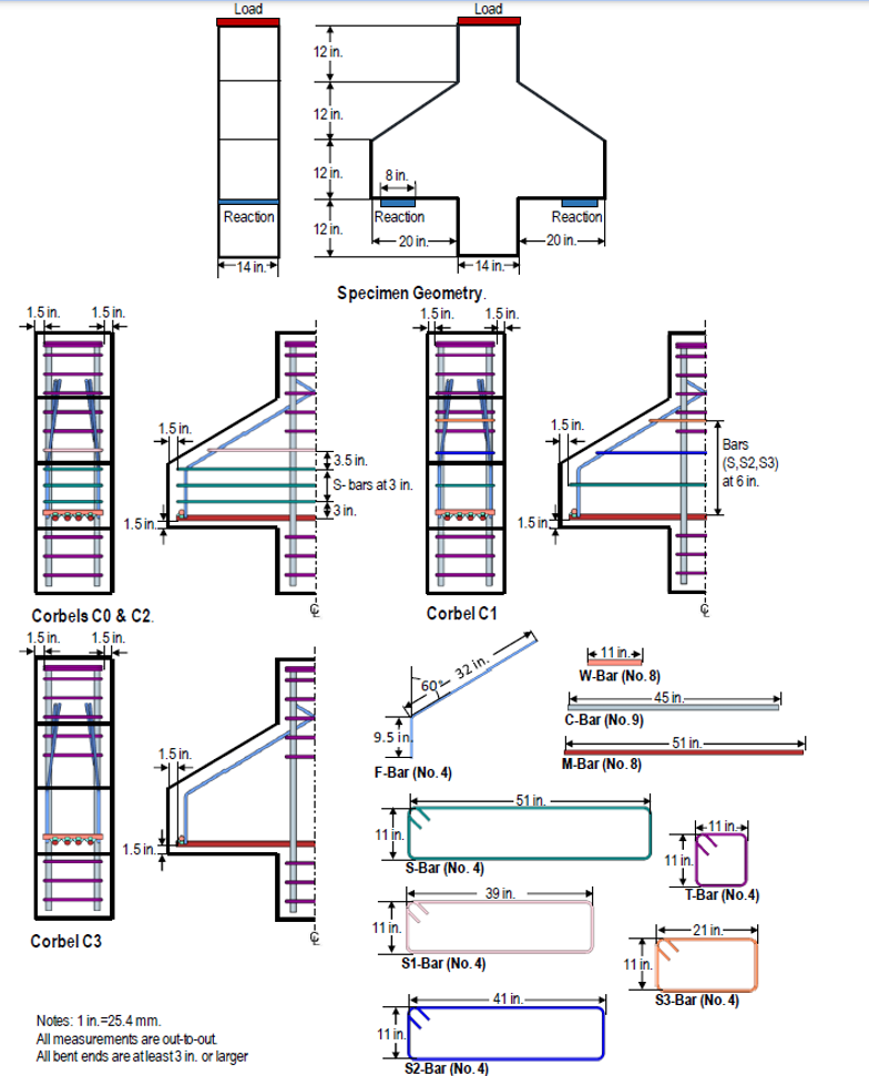
Figure 1.1: Specimen design with reinforcement detailing (Wilson, 2017).
Code Design Calculations per ACI 318-19
The code-based design checks were performed, and the capacities of the corbel specimens were calculated using the strut and tie model (STM), and the crack-control requirements for RC corbels were numerically investigated following the provisions of ACI 318-19. In the strut and tie model the concrete members are substituted with a hypothetical truss comprising concrete struts and steel ties, interconnected at nodes. As per the STM provisions of ACI 318-19, adequate reinforcement must be provided to meet the strength demands of each tie. To ensure adequate crack control and prevent excessive strain incompatibility, it is required that the angle between the axis of any strut and any tie entering a node be greater than or equal to 25°. Three types of nodes are categorized: CCC nodes, indicating nodes with no ties (compression-compression-compression node); CCT nodes, representing nodes with one tie; and CTT nodes, denoting nodes with two or more ties.
The strut-and-tie truss model used for designing these specimens is illustrated in Figure 1.15. The horizontal alignments of Nodes A and A' were aligned with the center of the bearing plates, while Nodes B and B' were positioned at the quarter points within the column width. The vertical positioning of Nodes B and B' was determined as the midpoint of the rectangular compression block at the column face. The design process involved verifying the yield strength of Tie AA', the compressive strength of Struts AB, A'B', BB', BC, and B'C', and the back, bearing, and inclined faces of Nodes A, A', B, and B'.
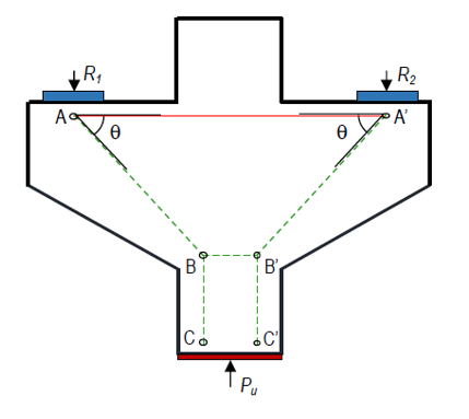
Figure 1.15: Strut-and-tie model (Wilson, 2017).
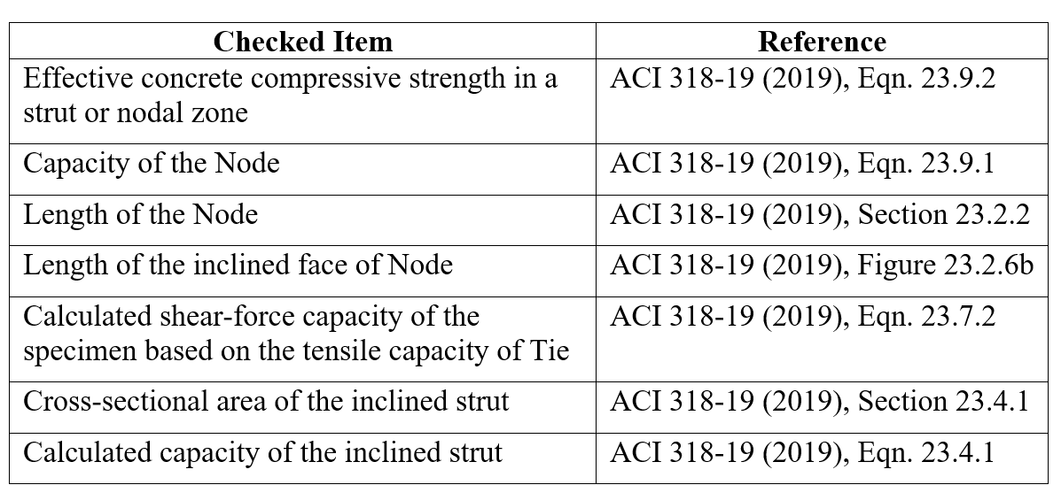
Table 1.6 presents the design checks identified for corbel specimens from ACI 318-19. The structural integrity of concrete elements is rigorously assessed through various checked items, each referencing the American Concrete Institute (ACI) 318-19 building code.
IDEA StatiCa Analysis
Seven reinforced concrete corbels described in the Sections 1.2.1 and 1.2.2 were modeled by the CFSM method implemented in IDEA StatiCa Detail to simulate the response of these specimens. The measured compressive strength of concrete, yield strength of reinforcing steel, and ultimate strength of reinforcing steels, as presented by Wilson (2017) for specimens C0, C1, C2, and C3 (Table 1.3), and by Khosravikia et al. (2018) for specimens S1, S2, and S3, were incorporated into IDEA StatiCa Detail.
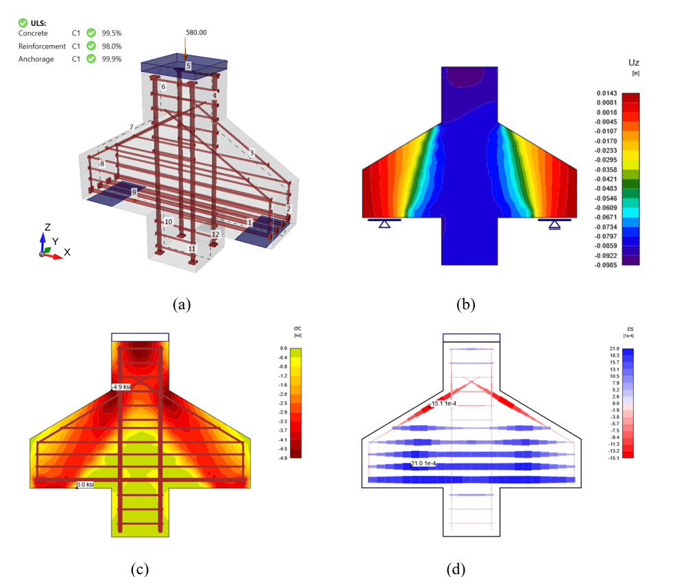
Figure 1.16: (a) Corbel C0 at 580 kips (2578 kN) loading, (b) deflection of C0 under 580 (kips) loading, (c) concrete principal stress σ_c of C0 at 580 (kips) loading, and (d) strain in the reinforcement steel.
ABAQUS Model Development and Analysis
In this section, the baseline model developed in Section 1.4.1 (i.e., Specimen C0) was reconstructed using ABAQUS software (version 2023) for finite element (FE) analysis, and the results were compared with those obtained from IDEA StatiCa. In the model, in addition to the self-weight, the vertical load of 592 kips (2633 kN) was imposed to the top bearing plate as illustrated in Figure 1.23a. Two boundary conditions similar to the experimental tests and IDEA StatiCa model (i.e., roller type in right and tilt-saddle type in left) were applied to Specimen C0 (see Figure 1.23b).
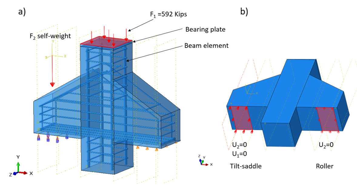
Figure 1.23: a) Model setup in ABAQUS, and b) implementation of two boundary conditions in ABAQUS.
The required parameters to describe this model were obtained from the experimental test after calibration as they were not explicitly indicated in Ref. (Wilson, 2017). For the steel bars, the material behavior was modeled using simple bi-linear plasticity. Other parameters, including density, elastic modulus, and Poisson’s ratio were taken from IDEA StatiCa Detail materials library. The numerical simulation was carried out on a virtual machine with 16 processors (Intel Xenon® Gold Processor 6430 @2.10GHz) and took approximately 56 minutes to finish, while IDEA StatiCa Detail completed the calculation in less than one minute.
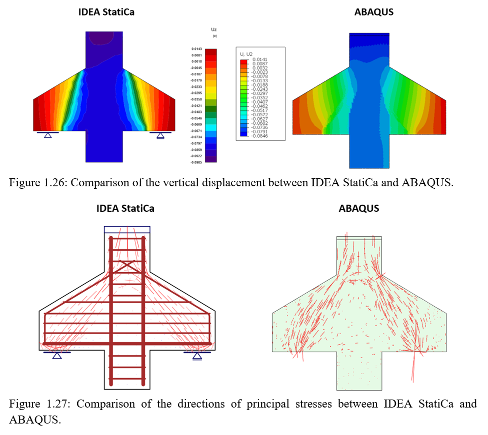
Figure 1.26, 1.27 Comparison of pricipal stresses direction and vertical displacement between IDEA StatiCa Detail and ABAQUS.
Summary
Seven reinforced concrete corbels were investigated using IDEA StatiCa and following the provisions of strut-and-tie method per ACI 318-19 for four different corbels (C0, C1, C2, C3) and per AASHTO LRFD (2016) for three different corbel specimens (S1, S2, S3). Also, the results from the IDEA StatiCa baseline model (i.e., Corbel C0) were compared with those from the equivalent ABAQUS model. The specimens were modeled and analyzed using IDEA StatiCa to capture the experimental behavior of the corbels. The maximum load-carrying capacity of the corbels and the load versus mid-point deflection curves were plotted with the results obtained from IDEA StatiCa and compared with the measured data.
In Figure 1.30, comparisons of the loads obtained from experiments, strut and tie method (STM) and IDEA StatiCa for specimens C are presented. The results highlight the effectiveness of PIDEA StatiCa in closely aligning with experimental results, surpassing traditional methods such as the STM in providing near-accurate predictions of corbel performance. Across all specimens (C0, C1, C2, and C3), PIDEA StatiCa consistently demonstrates close agreement with the experimental maximum load capacities (Pmax). The properties of the specimens C0 and C2 were the same but the specimen C0 was tested with a greater av /d ratio. This exhibits the effect of av /d ratio on the load-carrying capacity of corbel. The capacity of the corbels inversely varied with the av /d ratio.
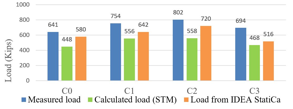
Figure 1.30: Comparison of measured, calculated (STM) and maximum load from IDEA StatiCa for C specimens.
In summary, across all seven corbel specimens (C0 to C3 and S1 to S3), the maximum loads predicted by IDEA StatiCa consistently surpassed those of the STM and closely aligned with experimental results, apart from specimens S1 and S3. Specifically, for S1 and S3, the maximum loads derived from IDEA StatiCa exceeded the measured values by 1.5% and 3.1%, respectively.Overall, the results from experimental testing, the strut and tie model (STM), IDEA StatiCa, and ABAQUS compare reasonably.
Regarding the performance of IDEA StatiCa, it is apparent that results are comparable to those of ABAQUS. This indicates that IDEA StatiCa is capable of accurately simulating and analyzing structural behavior. The effectiveness and reliability of the software for engineering analysis and design tasks are underscored by its ability to deliver results in line with established tools like ABAQUS. Nonetheless, it is always advisable to ensure accuracy and reliability for specific applications by validating results from any software with experimental data or alternative numerical methods. Further refinement and validation of analytical models could enhance the accuracy of predictions, ensuring more robust structural analysis and design processes.