Idea Statica
  • Steel
  • Concrete
  • BIM & workflows
  • Support & Learning
  • Pricing
  • Company
  • Steel overview
  • Connection design
  • Member design
  • Parametric design
  • Steel case studies
  • Concrete overview
  • Walls and D-regions
  • Anchoring design
  • Members & cross-sections
  • Concrete case studies
  • BIM overview
  • Supported integrations
  • Checkbot
  • Viewer
  • APIs
  • Support Center
  • E-learning & certification
  • Blog
  • Downloads & Licensing
  • Plans
  • Free community tool
  • Enterprise customers
  • Students & educators
  • How much will you save?
  • About us
  • Contact
  • Research & development
  • Authorized resellers
  • Meet our customers
  • Career
  • Steel
    Steel overviewConnection designMember designParametric designSteel case studies
  • Concrete
    Concrete overviewWalls and D-regionsAnchoring designMembers & cross-sectionsConcrete case studies
  • BIM & workflows
    BIM overviewSupported integrationsCheckbotViewerAPIs
  • Support & Learning
    Support CenterE-learning & certificationBlogDownloads & Licensing
  • Pricing
    PlansFree community toolEnterprise customersStudents & educatorsHow much will you save?
  • Company
    About usContactResearch & developmentAuthorized resellersMeet our customersCareer
14-Day Trial
14-Day Trial
  • Steel
  • Concrete
  • BIM & workflows
  • Support & Learning
  • Pricing
  • Company

Subscribe to our newsletter

Company

  • About us
  • Partners
  • Careers
  • Patent

Resources

  • Customer projects
  • Case studies
  • Connection Library
  • Verification books

Legal

  • EULA
  • Privacy policy
  • California Privacy
  • TOS Viewer
  • Licensing

Help

  • Contact
  • Quote request
  • Resellers
  • Downloads
FacebookInstagramLinkedInYouTube

© IDEA StatiCa 2009-2026

Trusted and used worldwide by engineers, fabricators & consultants.

Support CenterKnowledge Base ArticlesCode-check of bolts and preloaded bolts according to Chinese standard
Advanced analysis types for your steel structures
Bolts are too close to plate edge
Traffic lights for forces in bolts
Prying and high tension force in bolts
Bolt shear force calculated per shear plane
Through-bolts in hollow sections: design them as pins, not bolts
Bolt bearing distances for Eurocode
Warnings for welds and bolts connecting the same plates
Slip resistance check update according to SP 16
Detailing improvements for bolts and welds in Eurocode
Angle to the grain of the steel-to-timber connections
Filler plate (packing plate) recognition
Smooth results with precise meshing
Code-check of bolts and preloaded bolts according to Australian standards
Code-check of bolts and preloaded bolts according to Chinese standard
Code-check of bolts according to Hong Kong Code
Code-check of bolts and preloaded bolts according to Hong Kong Code
Code-check of bolts according to Indian standard
Code-check of preloaded bolts according to Indian standards
Code-check of bolts and preloaded bolts according to Russian standards
The forces in bolts, including prying forces, are determined by finite element analysis. The bolt resistances are checked by GB 50017. Structural design of bolted steel connections.
Connection designSteelKnowledge baseConnectionCBFEM

Code-check of bolts and preloaded bolts according to Chinese standard

This article is also available in
ENCZDEESFRITPTNLHUROKRPLTHTRVIZH

Bolts

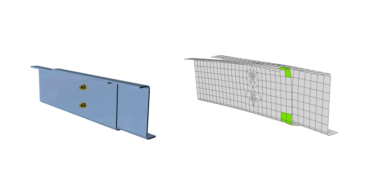
Bolts are checked according to GB 50017, Cl. 11.4. The tensile and shear force in each bolt is determined by finite element analysis. Prying forces are determined by finite element analysis and taken into account. Each shear plane is checked individually. The plate in the bearing is checked against the sum of shear forces at nearby planes.

Design tensile and shear strengths of a bolt; fub[MPa] – ultimate strength of a bolt; derived from Table 4.4.6

fubf_{ub}fub​ [MPa]ftbf_t^bftb​fvbf_v^bfvb​
fub≤400f_{ub} \le 400fub​≤4000.425⋅fub0.425 \cdot f_{ub}0.425⋅fub​0.35⋅fub0.35 \cdot f_{ub}0.35⋅fub​
400<fub<830400<f_{ub}<830400<fub​<8300.42⋅fub0.42 \cdot f_{ub}0.42⋅fub​0.38⋅fub0.38 \cdot f_{ub}0.38⋅fub​
830≤fub830 \le f_{ub}830≤fub​40/83⋅fub40/83 \cdot f_{ub}40/83⋅fub​32/83⋅fub32/83 \cdot f_{ub}32/83⋅fub​

Bolt in tension

A bolt subject to a tensile force is designed according to Cl. 11.4.1.2 and shall satisfy:

Nt≤Ntb=As⋅ftbN_t \le N_t^b = A_s \cdot f_t^bNt​≤Ntb​=As​⋅ftb​

where:

  • Nt – tensile force in a bolt
  • Ntb – design tension capacity
  • As=πde24A_s = \frac{\pi d_e^2}{4}As​=4πde2​​ – tensile stress area of a bolt
  • de – effective diameter of a bolt at threaded section
  • ftb – design tensile strength of a bolt

Bolts in shear

A bolt subject to a shear force is designed according to Cl. 11.4.1.1 and shall satisfy:

Nv≤Nvb=Ag⋅fvbN_v \le N_v^b = A_g \cdot f_v^bNv​≤Nvb​=Ag​⋅fvb​

where:

  • Nv – shear force in a bolt in investigated plane
  • Ag=πd24A_g = \frac{\pi d^2}{4}Ag​=4πd2​ – gross cross-section area of a bolt
  • d – nominal diameter of a bolt
  • fvb – design shear strength of a bolt

Each shear plane is checked individually, i.e. number of shear planes nv = 1.

Bolts in combined tension and shear

A bolt loaded in shear and tensile forces at the same time is designed according to Cl. 11.4.1.3 and shall satisfy:

(NvNvb)2+(NtNtb)2≤1.0\sqrt{\left ( \frac{N_v}{N_v^b} \right ) ^2 + \left ( \frac{N_t}{N_t^b} \right ) ^2} \le 1.0(Nvb​Nv​​)2+(Ntb​Nt​​)2​≤1.0

where:

  • Nv – shear force in a bolt in investigated plane
  • Nt – tensile force in a bolt
  • Nvb – design shear resistance of a bolt
  • Ntb – design tensile resistance of a bolt

Bolts in bearing

A plate subject to a bearing force due to a bolt in shear is designed according to Cl. 11.4.1.1 and shall satisfy:

Nv≤Ncb=d⋅t⋅fcbN_v \le N_c^b = d\cdot t \cdot f_c^bNv​≤Ncb​=d⋅t⋅fcb​

where:

  • Nv – shear force in acting on a plate; vector sum of shear forces in nearby planes
  • d – nominal bolt diameter
  • t – plate thickness
  • fcb – design bearing strength of a plate

Design bearing strength of a plate; fu – ultimate strength of a plate; derived from Table 4.4.6

Preloaded bolts

High strength bolt in friction type joint is designed according to Cl. 11.4.2.

Preloaded bolts in tension

The tensile resistance of a preloaded bolt is determined as:

Nt≤Ntb=0.8⋅PN_t \le N_t^b = 0.8 \cdot PNt​≤Ntb​=0.8⋅P

where:

  • Nt – tensile force in a bolt
  • Ntb – design tension capacity
  • P – pretension of a high strength bolt – Table 11.4.2-2

Table 11.4.2-2 – pretension of a high strength bolt P [kN]

Bolt gradeM16M20M22M24M27M30
8.880125150175230280
10.9100155190225290355

A preloaded bolt which is not in Table 11.4.2-2 subject to a tensile force is designed according to Cl. 11.4.1.2 and shall satisfy:

Nt≤Ntb=As⋅ftbN_t \le N_t^b = A_s \cdot f_t^bNt​≤Ntb​=As​⋅ftb​

where:

  • Nt – tensile force in a bolt
  • Ntb – design tension capacity
  • As=πde24A_s = \frac{\pi d_e^2}{4}As​=4πde2​​ – tensile stress area of a bolt
  • de – effective diameter of a bolt at threaded section
  • ftb – design tensile strength of a bolt

Preloaded bolts in shear

The design resistance of a preloaded bolt in shear is determined according to Cl. 11.4.2.1:

Nv≤Nvb=0.9kμPN_v \le N_v^b = 0.9 k \mu PNv​≤Nvb​=0.9kμP

where:

  • Nv – shear force in investigated plane
  • Nvb – design shear resistance of a bolt
  • k – factor for bolt holes; k = 1 for normal holes, k = 0.85 for oversized holes, k = 0.6 for slotted holes
  • μ – slip coefficient at friction interface taken from Table 11.4.2-1; editable in Code setup
  • P = Ntb / 0.8 – pretension of a high strength bolt for bolts which are not in Table 11.4.2-2

Each shear plane is checked individually, i.e. number of shear planes nf = 1.

Preloaded bolts in combined tension and shear

A bolt loaded in shear and tensile forces at the same time is designed according to Cl. 11.4.2.3 and shall satisfy:

NvNvb+NtNtb≤1.0\frac{N_v}{N_v^b} + \frac{N_t}{N_t^b} \le 1.0Nvb​Nv​​+Ntb​Nt​​≤1.0

where:

  • Nv – shear force in investigated plane
  • Nt – tensile force in a bolt
  • Nvb – design shear resistance of a bolt
  • Ntb – design tensile resistance of a bolt
Related articles

Strain check is performed at shell finite elements simulating plates. Von Mises yield criterion with design yield strength is used. IDEA StatiCa - structural analysis software for steel member design.
  • Steel
  • Connection
  • CBFEM
  • Plates
  • GB (China)
  • +5
  • Steel
  • Connection
  • CBFEM
  • Plates
  • GB (China)

Knowledge base

Code-check of steel plates according to Chinese Standard

Read more
Fillet welds are checked according to GB 50017 - Chapter 11. The strength of butt welds is assumed the same as the base metal and is not checked. Structural design of welded steel connections and steel beam to column connection details.
  • Steel
  • Connection
  • CBFEM
  • Welds
  • GB (China)
  • +5
  • Steel
  • Connection
  • CBFEM
  • Welds
  • GB (China)

Knowledge base

Code-check of welds according to Chinese standard

Read more
How to define pre-loaded bolts
  • Steel
  • Connection
  • AISC (USA)
  • Bolts
  • Contacts
  • EN (Eurocode)
  • +6
  • Steel
  • Connection
  • AISC (USA)
  • Bolts
  • Contacts
  • EN (Eurocode)

Knowledge base

How to define preloaded bolts

Read more
Workflows for preloaded bolts
  • Steel
  • SLS
  • Connection
  • Bolts
  • +4
  • Steel
  • SLS
  • Connection
  • Bolts

Webinar

Summer Series - Workflows for preloaded bolts

Read more