
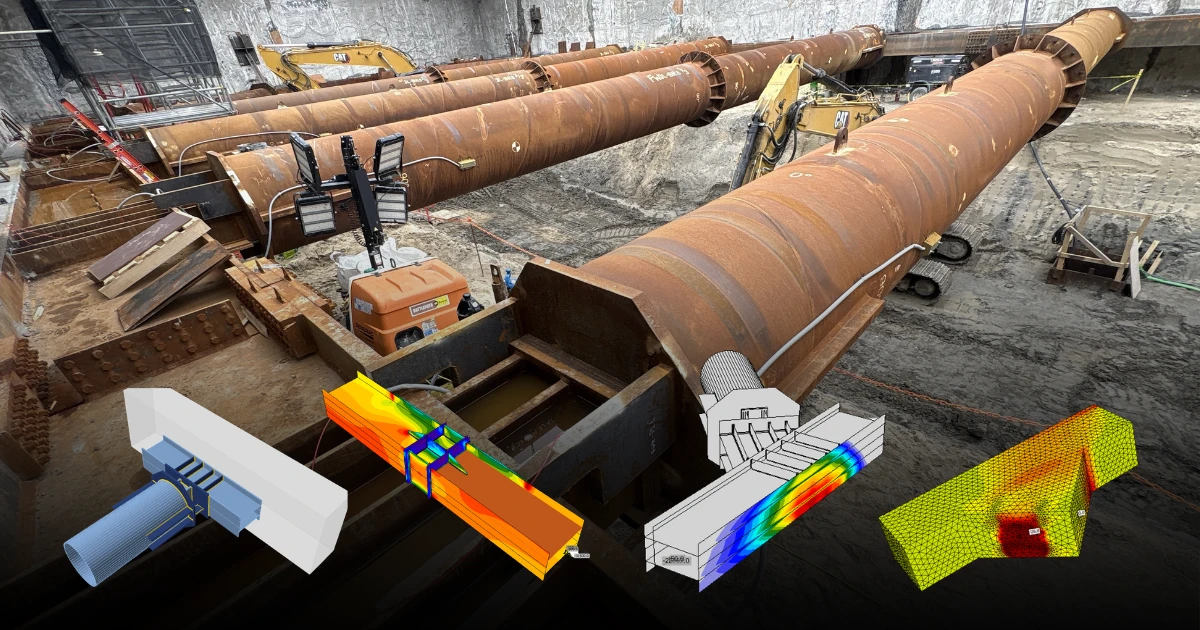


About the project
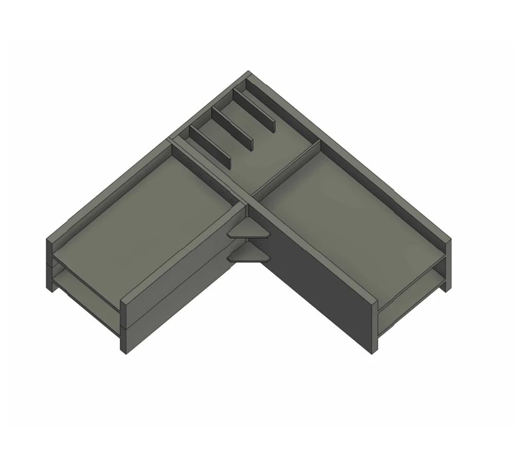
The support of excavation (SOE) system is built from reinforced concrete diaphragm walls (D-walls) tied together by an internal steel bracing system. It is a temporary structure that makes it possible to build the permanent below-grade station box, which is where the subway runs and stops. The focus here is the design and verification of the prefabricated steel connections that make up that temporary bracing.
The steel plate elements conform to CAN/CSA G40.20-13 / G40.21-13, Grade 350W, and the pipe struts conform to ASTM A252M-19 Grade 3. Where bolted connections are used, they rely on high-strength bolts conforming to ASTM A490M. The steel is manufactured both locally and in some instances, overseas, and is then sent to each site for assembly and erection. Grounded Engineering is the Engineer of Record (EoR) for two locations and is responsible for connection detailing at the other.
Engineering challenges
Lateral earth pressures on the SOE system were worked up using apparent earth pressure diagrams to set representative design envelopes. Those envelopes, along with the conditions below, were used to establish the connection design forces for axial load, shear, and bending moment:
- Hydrostatic pressure
- Construction surcharges
- Frost action and thermal effects
- Traffic decking and gantry crane loads
- Accidental loads
- Eccentric loads
The internal bracing carries substantial axial force, which means the connections between the bracing members and the diaphragm walls are heavily loaded. Grounded Engineering developed the initial designs using engineering mechanics together with CSA S16, CSA S6, CSA A23.3, and AISC provisions where applicable. Those methods gave a reliable first-order read on connection capacity, but by their nature they simplify how the connection actually behaves.
The combination of complex geometry, high loads, and the interaction between steel and concrete made several effects difficult to pin down by hand. Stress redistribution, stress concentrations, plate flexibility, prying action, three-dimensional load flow, connection stiffness, and local stability all fall into that category. On top of that, a prescribed 50 mm construction eccentricity added moments and deformation that are not easy to capture with conventional hand calculations.

Constructability added another layer. The connection assemblies are large and complex, so fabrication tolerances, erection clearances, and potential clashes all had to be checked. And because field conditions kept evolving during construction, the team needed a quick way to look at as-built configurations and work out practical remedial solutions when something changed.
Solutions and results
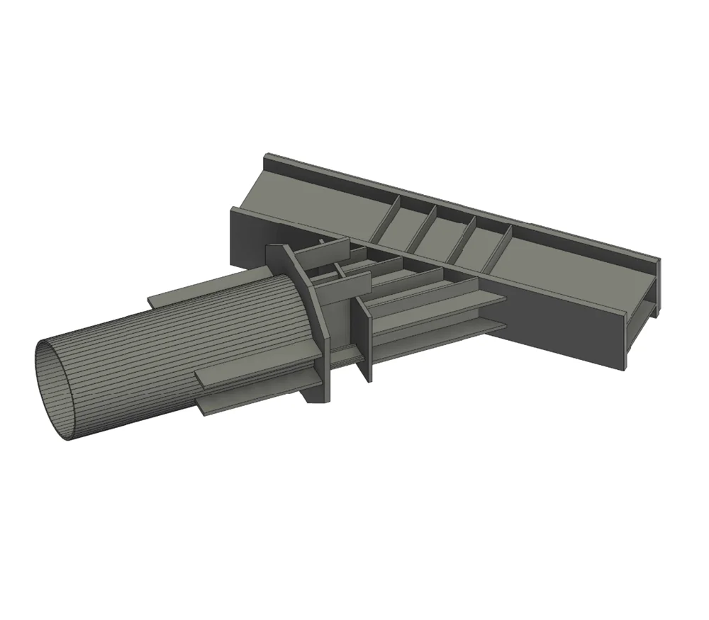
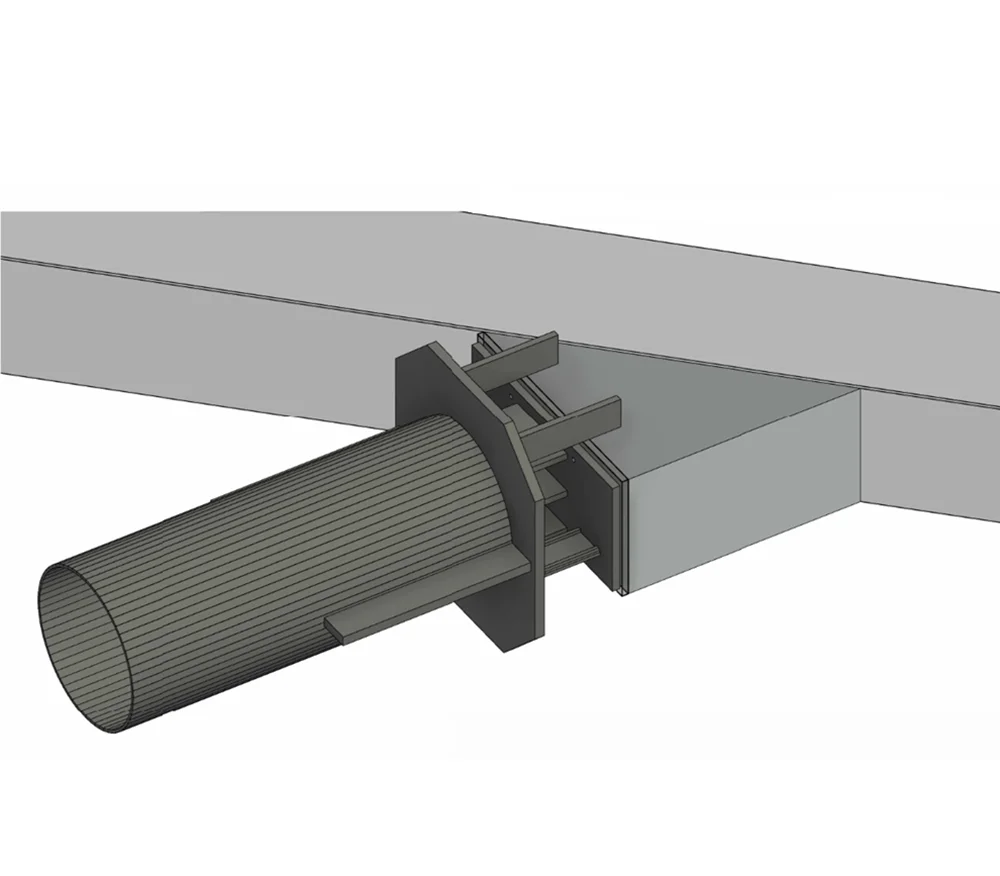
To work through these connections, Grounded Engineering used IDEA StatiCa Connection for the steel joints and carried the concrete side into IDEA StatiCa Detail. In Connection, the Component-Based Finite Element Method (CBFEM) handled the plates, welds, bolts, and the anchoring of the bracing into the diaphragm wall. Detail was then used to verify the reinforced concrete region where those forces are delivered into the wall.
The CBFEM analyses supplemented the traditional calculations rather than replacing them. They captured behavior that the hand methods could only approximate, including three-dimensional load paths, plate deformation, prying, weld behavior, and the interaction between the steel and the reinforced concrete. The 50 mm construction eccentricity was built directly into the models, so the secondary effects and connection deformations tied to that offset could be looked at explicitly.
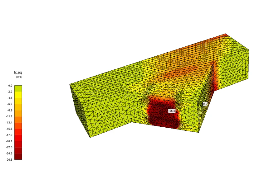
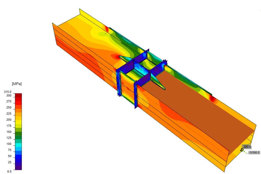
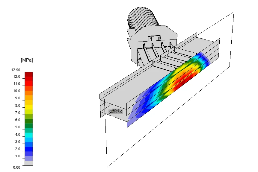
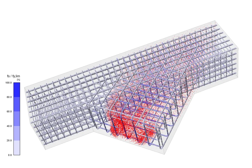
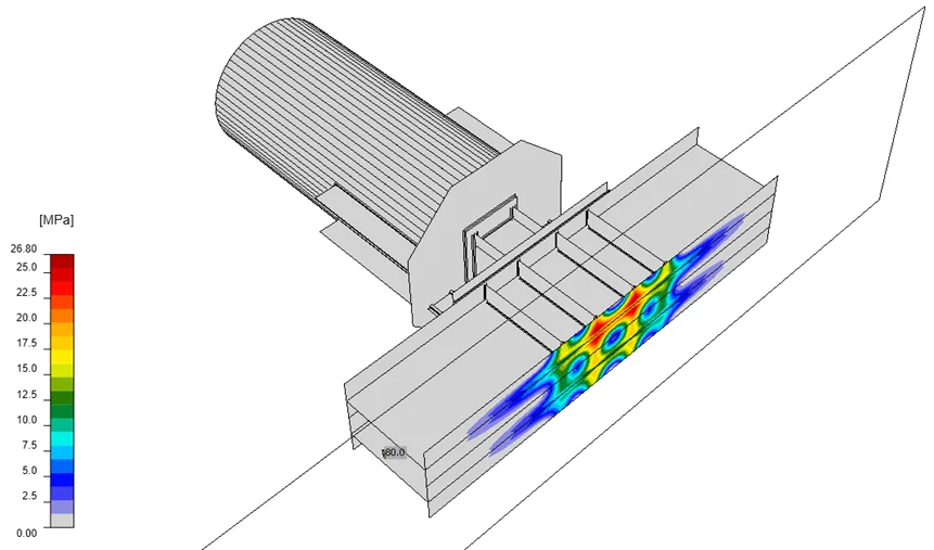
It is worth noting that the analysis did not replace the team's engineering judgment. It gave the team added confidence in the design assumptions and highlighted areas where individual connection components could be optimized. The final design package reflected that balance, with 115 pages of hand calculations supported by 81 pages of IDEA StatiCa output.
The 3D models also helped on the constructability side. Being able to look at the full connection assembly in three dimensions let the team spot potential clashes and check erection tolerances before anything reached the field. When as-built conditions or field modifications came up during construction, those changes could be evaluated quickly, which helped determine whether remedial measures were needed while keeping the schedule impact down.
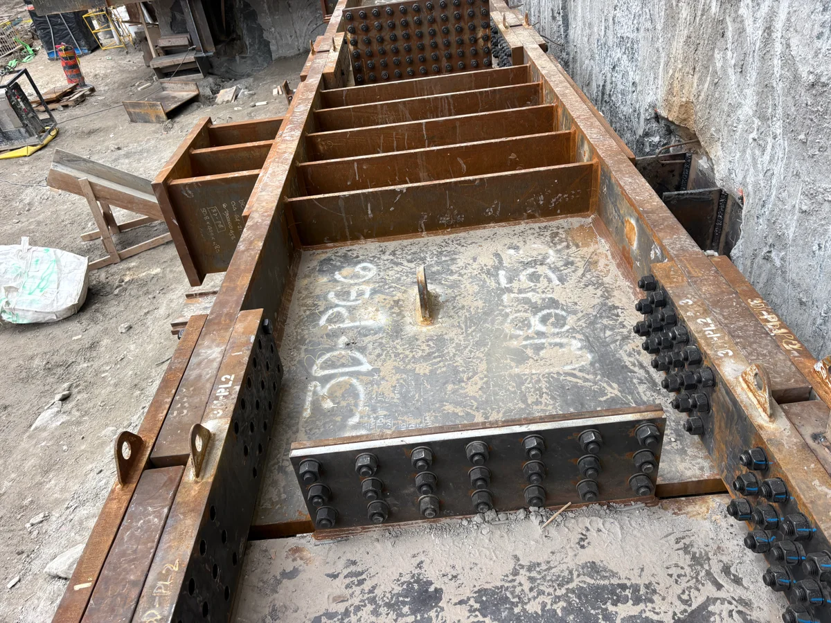

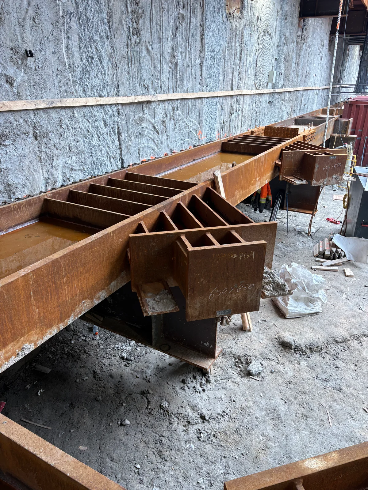

For coordination, the connection models were exported to IFC and DWG so they could be brought into Revit alongside the rest of the project data. That gave the engineering, drafting, and construction teams a shared 3D reference of each connection to work from, which is often where mistakes and unnecessary RFIs get caught early.
Grounded Engineering also noted that the software was only part of the story. From the initial kickoff through ongoing technical support, the IDEA StatiCa team stayed responsive and engaged with the project, and the continued development driven by user feedback made the software a useful partner over the course of the design.