Analiza rigidității și capacitatea de deformare a îmbinărilor din oțel
Îmbinările sunt clasificate în funcție de rigiditate ca rigide, semi-rigide și articulate. Inginerul trebuie să se asigure că rigiditatea îmbinării confirmă rigiditatea setată în software-ul CAE. Scopul analizei de rigiditate este de a obține distribuția corectă a încărcărilor în elemente și îmbinări, precum și săgețile corecte ale elementelor și ale structurii în ansamblu.
Metoda CBFEM analizează rigiditatea îmbinării elementelor individuale ale nodului. Pentru o analiză corectă a rigidității, trebuie creat un model de analiză separat pentru fiecare element analizat. Astfel, analiza de rigiditate nu este influențată de rigiditatea celorlalte elemente ale nodului, ci doar de nodul însuși și de construcția îmbinării elementului analizat. În timp ce elementul de reazem este rezemat pentru analiza de rezistență (elementul SL din figura de mai jos), toate elementele cu excepția celui analizat sunt rezemate în analiza de rigiditate (a se vedea cele două figuri de mai jos pentru analiza de rigiditate a elementelor B1 și B3). Excepție face baza stâlpului, unde rezemările sunt asigurate de fundația din beton; doar elementul analizat este încărcat, iar celelalte elemente au constrângeri doar în funcție de tipul lor de model.
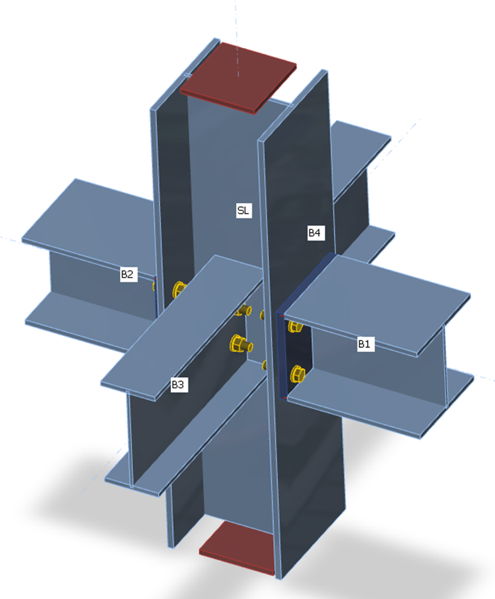
Rezemări pe elemente pentru analiza de rezistență
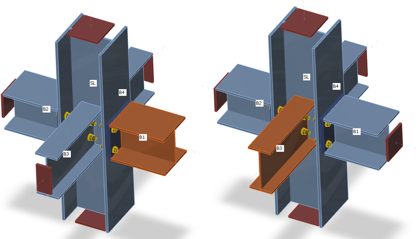
| Rezemări pe elemente pentru analiza de rigiditate a elementului B1 | Rezemări pe elemente pentru analiza de rigiditate a elementului B3 |
Încărcările pot fi aplicate doar elementului analizat. Dacă este definit momentul încovoietor My, se analizează rigiditatea la rotație în jurul axei y. Dacă este definit momentul încovoietor Mz, se analizează rigiditatea la rotație în jurul axei z. Dacă este definită forța axială N, se analizează rigiditatea axială a îmbinării.
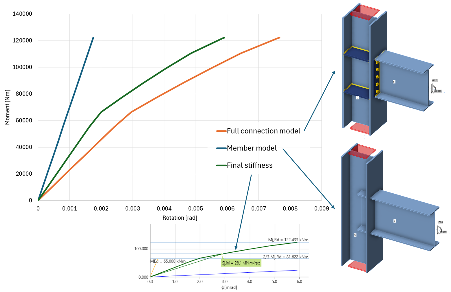
Curba moment-rotație (sau încărcare-deformație) este calculată pentru două modele:
- Modelul complet al îmbinării – cu elemente, plăci, șuruburi, suduri etc. (analiză material neliniară)
- Modelul de element – cu elemente conectate rigid în nod (analiză liniară elastică)
Diagrama afișată se obține prin scăderea modelului de element din modelul complet al îmbinării. Astfel, deformația elastică a elementelor, care este deja inclusă în modelul structurii de ansamblu, este exclusă.
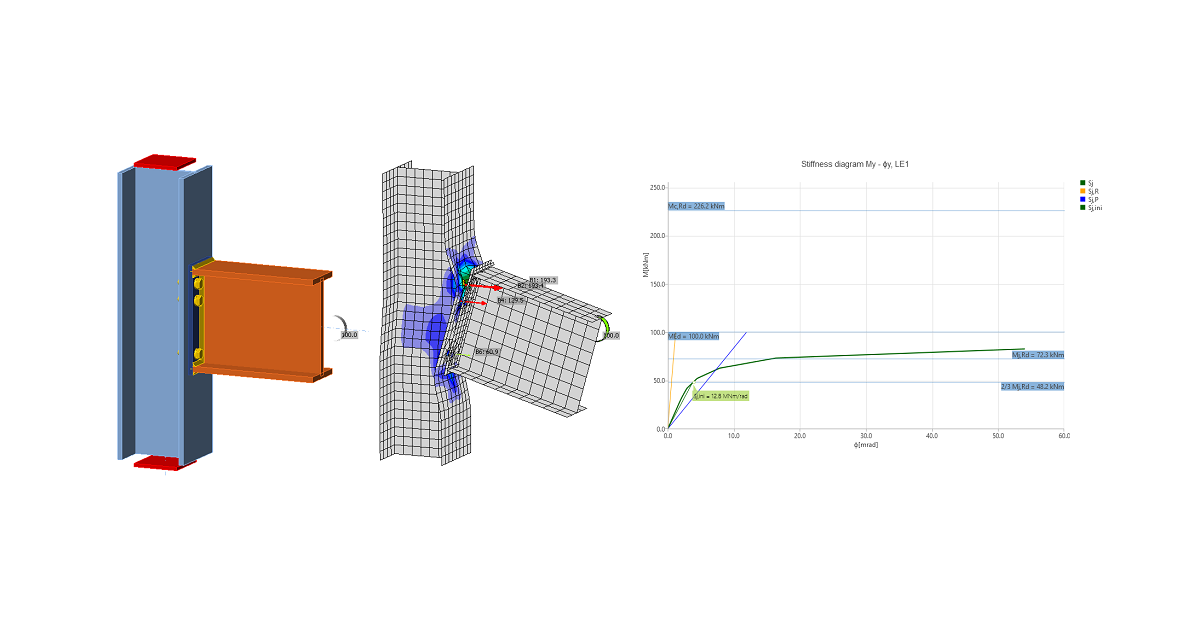
Programul generează automat o diagramă completă; aceasta este afișată direct în interfața grafică și poate fi adăugată în raportul de ieșire. Rigiditatea la rotație sau axială poate fi studiată pentru încărcări de calcul specifice. IDEA StatiCa Connection poate gestiona și interacțiunea cu celelalte forțe interioare.
Diagrama prezintă:
- Nivelul valorii de calcul a încărcării MEd
- Valoarea limită a capacității îmbinării pentru deformația echivalentă de 5% Mj,Rd; limita pentru deformația plastică poate fi modificată în configurarea codului
- Valoarea limită a capacității elementului conectat (utilă și pentru proiectarea seismică) Mc,Rd
- 2/3 din capacitatea limită pentru calculul rigidității inițiale
- Valoarea rigidității inițiale Sj,ini
- Valoarea rigidității secante Sjs
- Limite pentru clasificarea îmbinării – rigidă și articulată
- Deformația la rotație Φ
- Capacitatea de rotație Φc
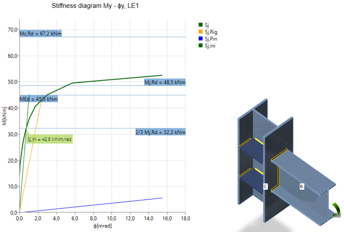
Îmbinare sudată rigidă
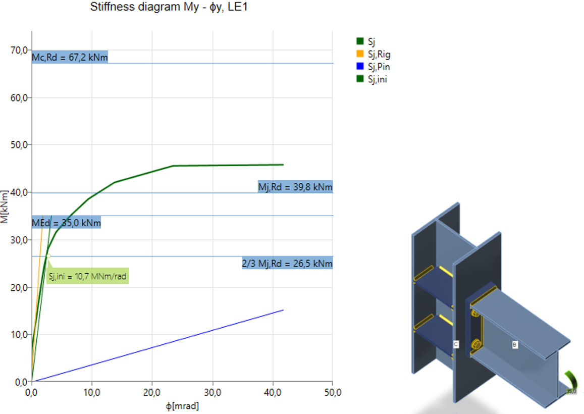
Îmbinare șurubată semi-rigidă
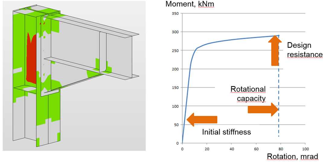
După atingerea deformației de 5% în inima stâlpului la forfecare, zonele plastice se propagă rapid
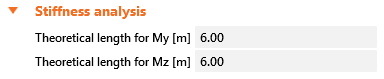
Nodul este clasificat în funcție de rigiditate în categoria rigidă, semi-rigidă sau articulată conform codului relevant. Lungimea teoretică a elementului poate fi setată pentru elementul analizat:
Cum se aplică încărcările?
În analiza de rigiditate, un singur element este încărcat și investigat. Elementul analizat poate fi încărcat cu:
- Forță normală N
- Forțe tăietoare Vy și Vz
- Momente încovoietoare My și Mz
- Torsiune Mx
Toate efectele de încărcare sunt aplicate simultan. Dacă încărcările aplicate sunt prea mici, acestea sunt toate amplificate printr-un factor astfel încât să fie atinsă rezistența nodului (forțele aplicate trebuie să fie mai mari decât 1). La crearea diagramelor moment-rotație sau încărcare-deformație, toate efectele de încărcare sunt amplificate proporțional în trepte.
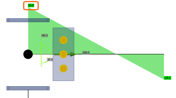
De exemplu, elementul analizat este încărcat cu:
- Forță normală N = 50 kN
- Forță tăietoare Vz = -80 kN
- Moment încovoietor My = 30 kNm
Rezistențele elementului sunt:
- Rezistența la forță normală NR = 2 111 kN
- Rezistența la forță tăietoare Vz,R = 763 kN
- Rezistența la moment încovoietor My,R = 226 kNm
Încărcările sunt înmulțite cu un factor:
\[ \alpha = \textrm{min} \left \{ \frac{N_R}{N}, \, \frac{M_{y,R}}{M_y}, \, \frac{M_{z,R}}{M_z} \right \} \]
De remarcat că, dacă forța tăietoare nu este aplicată în nod, adică acționează pe un braț de pârghie, momentul încovoietor este afectat. Momentul încovoietor în nod, așa cum apare în modelul tip cadru, este utilizat ca încărcare de referință.
În acest exemplu, factorul este \( \alpha = 7.53 \). Încărcările de referință sunt înmulțite și apoi aplicate în trepte, iar rezultatele sunt reprezentate în diagrama de rigiditate. Încărcările aplicate sunt împărțite în 12 trepte, iar când îmbinarea se apropie de rezistența sa, treptele sunt rafinate suplimentar. Exemplul primelor trei trepte este prezentat în tabelul următor:
| Încărcări de referință | Încărcări aplicate | Prima treaptă | A doua treaptă | A treia treaptă | |
| 100% | 8,33% | 16,67% | 25,00% | ||
| N | 50 | 377 | 31 | 63 | 94 |
| Vy | 0 | 0 | 0 | 0 | 0 |
| Vz | -80 | -603 | -50 | -100 | -151 |
| Mx | 0 | 0 | 0 | 0 | 0 |
| My | 30 | 226 | 19 | 38 | 57 |
| Mz | 0 | 0 | 0 | 0 | 0 |
Capacitatea de deformare
Capacitatea de deformare/ductilitatea δCd se alătură rezistenței și rigidității ca unul dintre cei trei parametri de bază care descriu comportamentul îmbinărilor. În îmbinările cu rezistență la moment, ductilitatea este asigurată printr-o capacitate de rotație suficientă φCd. Capacitatea de deformare/rotație este calculată separat pentru fiecare îmbinare din nod.
Software-ul estimează capacitatea de deformare ca punctul în care una dintre următoarele condiții este îndeplinită:
- Rezistența șurubului sau ancorei la întindere, forfecare sau interacțiunea întindere/forfecare este atinsă
- Rezistența sudurii este atinsă
- Deformația plastică în plăci atinge 15%
Estimarea capacității de rotație este importantă în îmbinările expuse la acțiuni seismice, a se vedea Gioncu și Mazzolani (2002) și Grecea (2004), și la încărcări extreme, a se vedea Sherbourne și Bahaari (1994 și 1996). Capacitatea de deformare a componentelor a fost studiată începând cu sfârșitul secolului trecut (Foley și Vinnakota, 1995). Faella et al. (2000) au efectuat teste pe console tip T și au derivat expresii analitice pentru capacitatea de deformare. Kuhlmann și Kuhnemund (2000) au efectuat teste pe inima stâlpului supusă compresiunii transversale la diferite niveluri ale forței axiale de compresiune în stâlp. Da Silva et al. (2002) au estimat capacitatea de deformare la diferite niveluri ale forței axiale în grinda conectată. Pe baza rezultatelor experimentale combinate cu analiza prin Metoda Elementelor Finite, capacitățile de deformare sunt stabilite pentru componentele de bază prin modele analitice de Beg et al. (2004). În această lucrare, componentele sunt reprezentate prin arcuri neliniare și combinate corespunzător pentru a determina capacitatea de rotație a nodului pentru îmbinările cu placă de capăt extinsă sau îngropată și îmbinările sudate. Pentru aceste îmbinări, componentele cele mai importante care pot contribui semnificativ la capacitatea de rotație au fost identificate ca: inima în compresiune, inima stâlpului în întindere, inima stâlpului la forfecare, talpa stâlpului la încovoiere și placa de capăt la încovoiere. Componentele legate de inima stâlpului sunt relevante doar atunci când nu există elemente de rigidizare în stâlp care să preia forțele de compresiune, întindere sau forfecare. Prezența unui element de rigidizare elimină componenta corespunzătoare, iar contribuția sa la capacitatea de rotație a nodului poate fi astfel neglijată. Plăcile de capăt și tălpile stâlpului sunt importante doar pentru îmbinările cu placă de capăt, unde componentele acționează ca o consolă tip T, incluzând și capacitatea de deformare a șuruburilor la întindere. Aspectele și limitele capacității de deformare a îmbinărilor din oțel de înaltă rezistență au fost studiate de Girao et al. (2004).