Comparison of LBA and GMNIA results in IDEA Member to experimental data and numerical solution
1. The objective
The objective of this article is the verification of the LBA (linear bifurcation analysis) module and the validation of the GMNIA (geometrically and materially nonlinear analysis with imperfections) module of the IDEA Member application. The resulting critical loads from IDEA Member are compared to a numerical solution from [1] and the resulting resistances are compared to both experimental data and numerical solution from [1].
2. Model description
A total of 9 individual cases was analyzed. These were acquired from the study [1], the designation of individual specimens was maintained (A1–A3), (A4–A6), and (E1–E3). Their real cross-section dimensions were considered, as well as their real material properties. Two different sets of boundary conditions were investigated (BC1 – rigid, BC2 – uniaxially hinged), there was also a variance in the column’s relative slenderness.

Fig. 1: Boundary conditions (left to right) rigid (A1–A3); uniaxially hinged (A4–A6); rigid (E1–E3)
3. Results
The inputs and results of the calculation are summarized in Table 1. The cross-section dimensions and material properties are presented, as well as the value of initial imperfection e0 assumed as L/300. This value is based on [2], where it is shown to best describe the behavior of angles in compression.
The critical load from IDEA Member (index M) is compared to a numerical solution [1] (index FEM). The ultimate resistance from IDEA Member (index M) is compared to a numerical solution [1] (index FEM) and to the experimental data as well (NR).
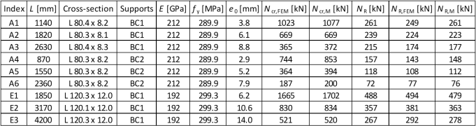
Tab. 1: Cross-section dimensions, material properties and results
3.1. Linear Buckling Analysis
The results of LBA verification are satisfactory, critical loads from both software solutions are very similar in all but one case (A4), where the difference in results is 13 %. In all the other cases, the difference is under 5 %.
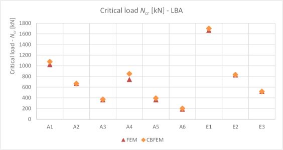
Chart 1: Critical load values for investigated specimens

Chart 2: Critical load comparison – FEM vs. CBFEM
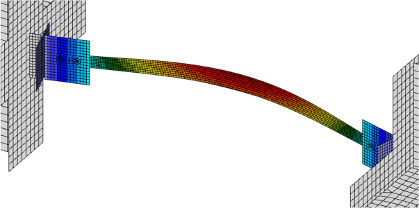
Fig. 2: First buckling mode shape from LBA (specimen A6)
3.2. Geometrically and Materially Nonlinear Analysis with Imperfections
The results of GMNIA validation show a good agreement with the experimental data.
There is also a good agreement when verifying the results of CBFEM to FEM, with the largest deviation under 5 %.
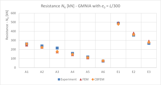
Chart 3: Ultimate resistance values
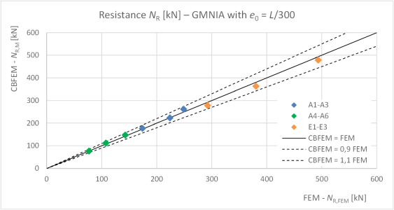
Chart 4: Ultimate resistance comparison – FEM vs. CBFEM
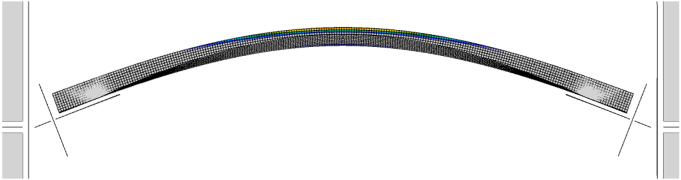
Fig. 3: GMNIA results – plastic strain at ultimate resistance (specimen A6)
4. Literature and References
[1] Kettler, M., Lichtl, G., Unterweger, H. Experimental tests on bolted steel angles in compression with varying end supports. Journal of Constructional Steel Research. 155 (2019). 301-315.
[2] Kettler, M., Taras, A., Unterweger, H. Member capacity of bolted steel angles in compression: Influence of realistic end supports. Journal of Constructional Steel Research. 130 (2017). 22–35.