
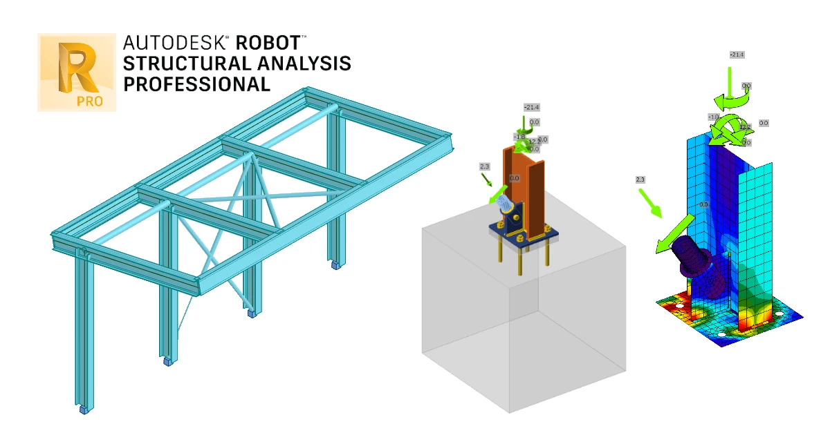


How to activate the link
- Download and install the latest version of IDEA StatiCa
- Make sure that you are using a supported version of your FEA solution
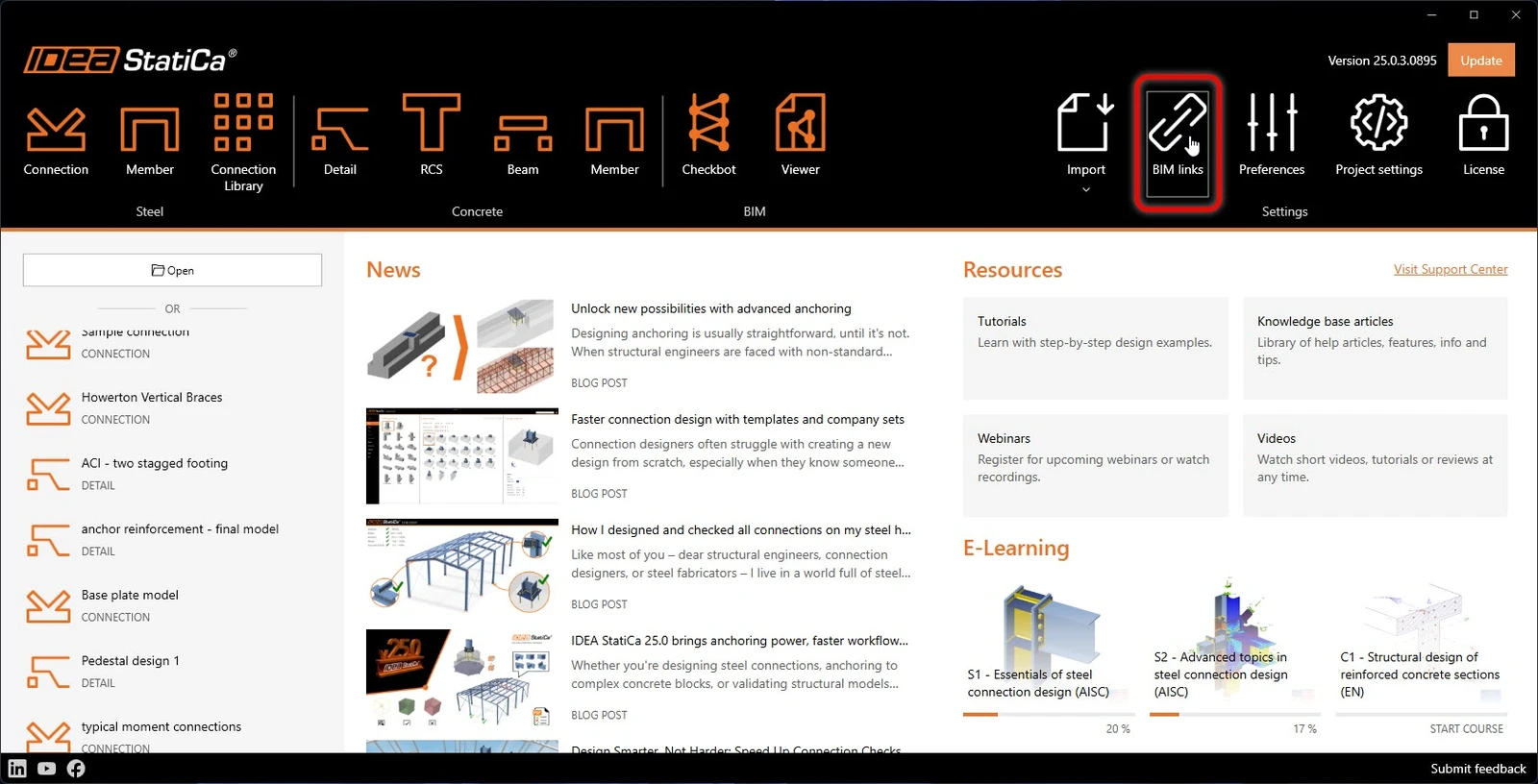
IDEA StatiCa integrates BIM links into your FEA software during its installation. You can check the status and eventually integrate more BIM links by running IDEA StatiCa and opening the BIM links. Please note that some FEA software require additional steps to fully activate their BIM link to IDEA StatiCa.
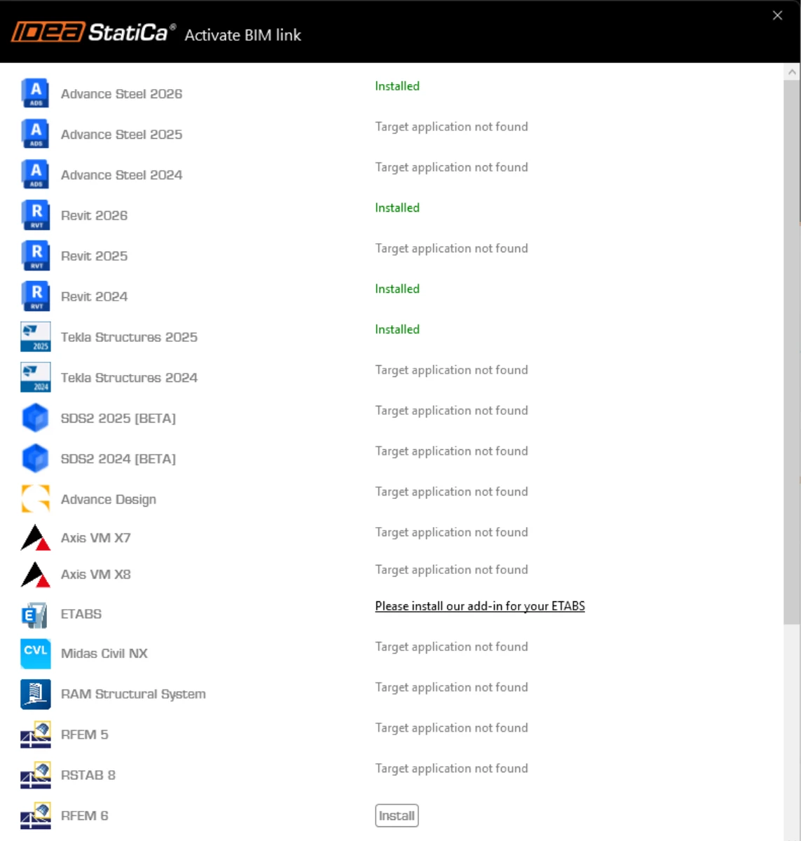
A notification "Do you want to allow this app to make changes to your device?" may appear, if so, please confirm with the Yes button.
By clicking Install, the BIM link for the selected software is integrated. The screen also tells you the status of other BIM links.
How to use the link
We have a RSA model for you to use: AISC.
Open the model in Robot Structural Analysis, calculate and save it.
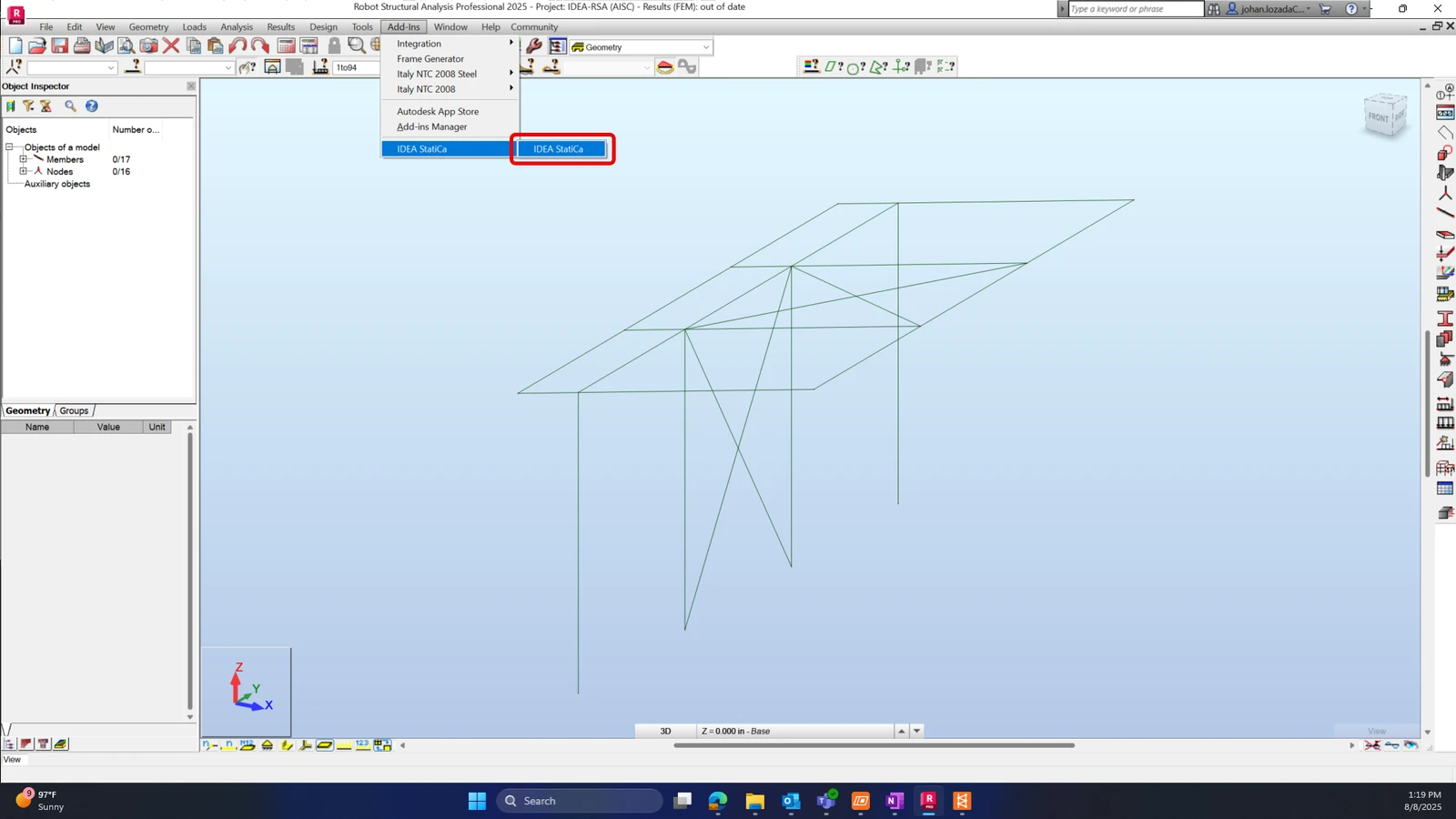
The BIM link should be automatically integrated. You can find it in the top ribbon under Add-Ins -> IDEA StatiCa -> IDEA StatiCa. This will open the Checkbot application.
Select the Checkbot option with design code AISC and then Create project.
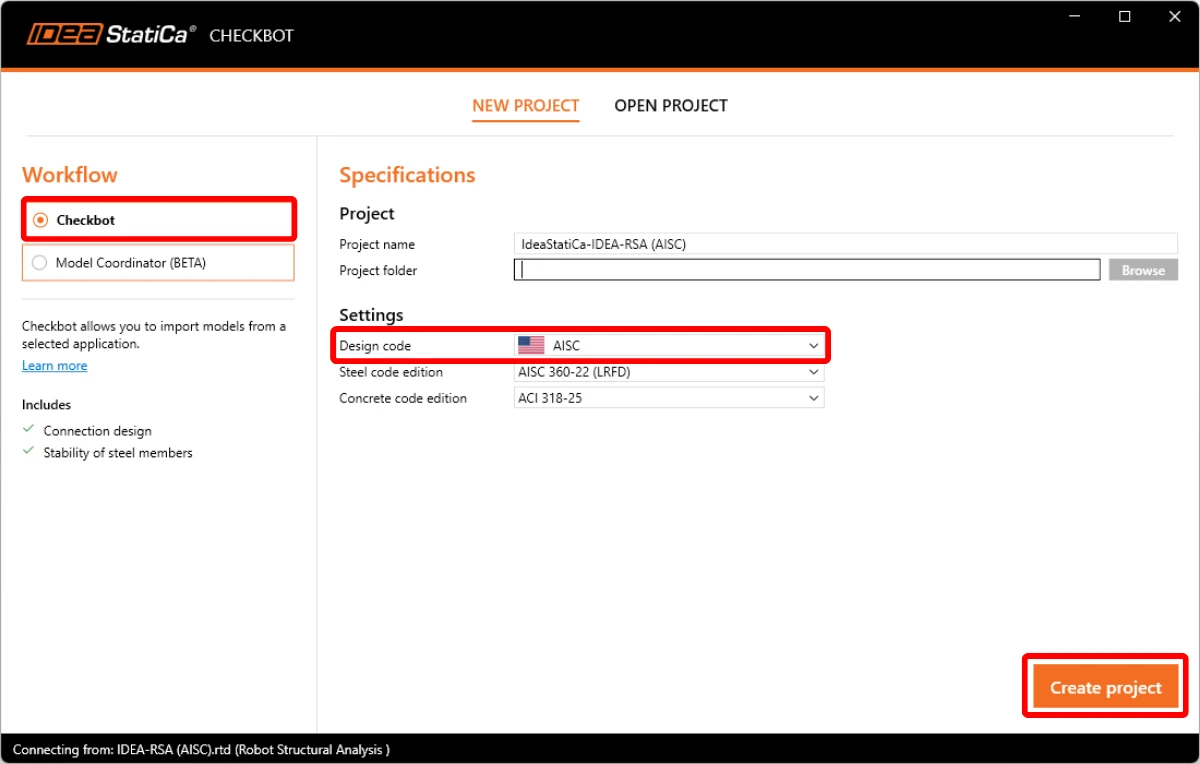
The new Checkbot project is ready to import connections from Robot Structural Analysis.
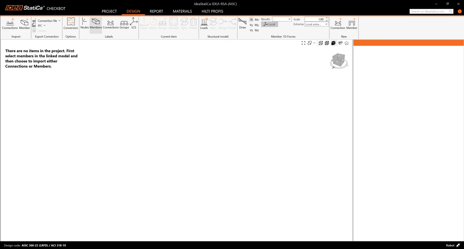
In Robot Structural Analysis, select one of the inside columns making sure you also select the lowest node.
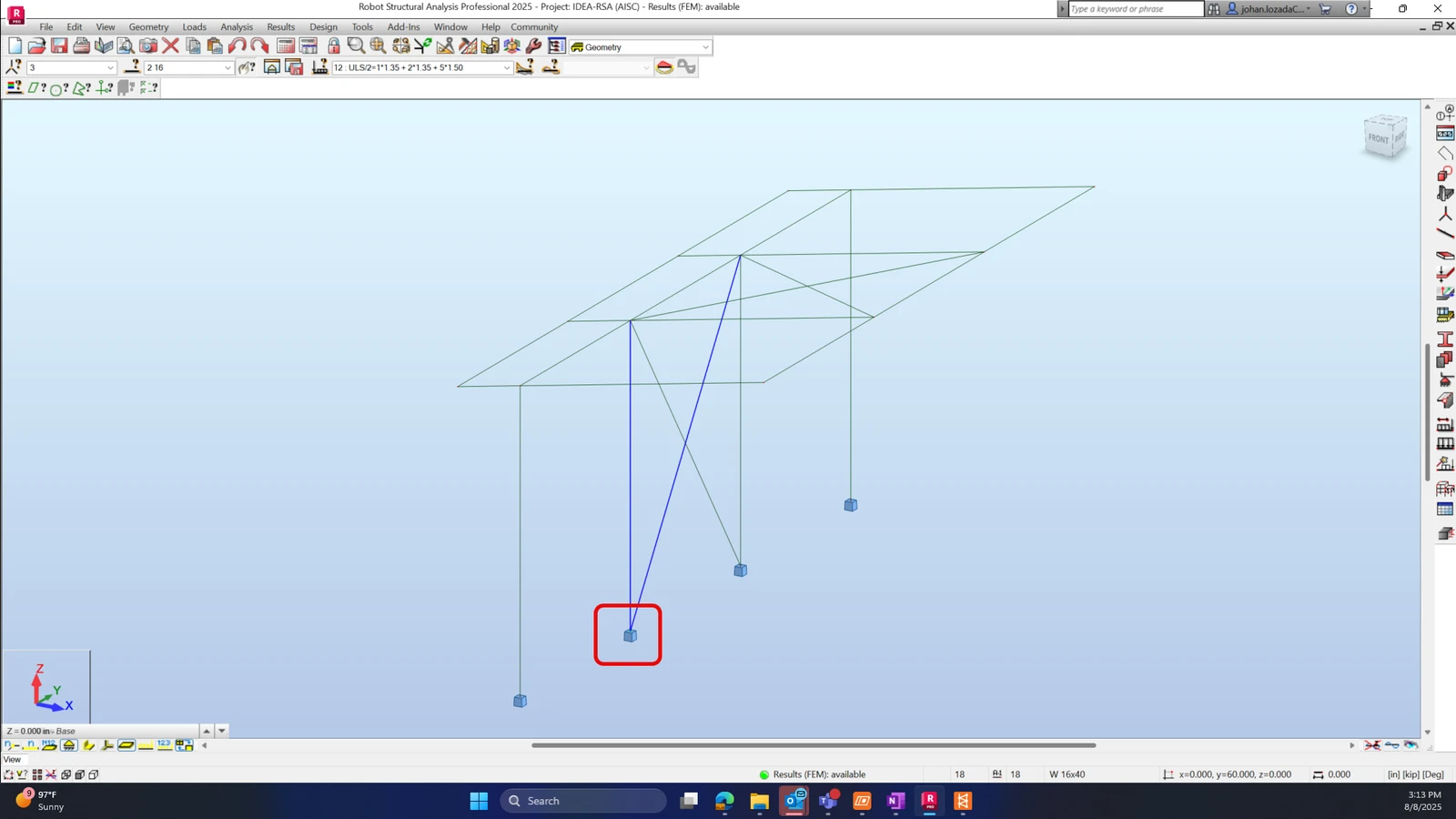
Import
Then in Checkbot select Connections.
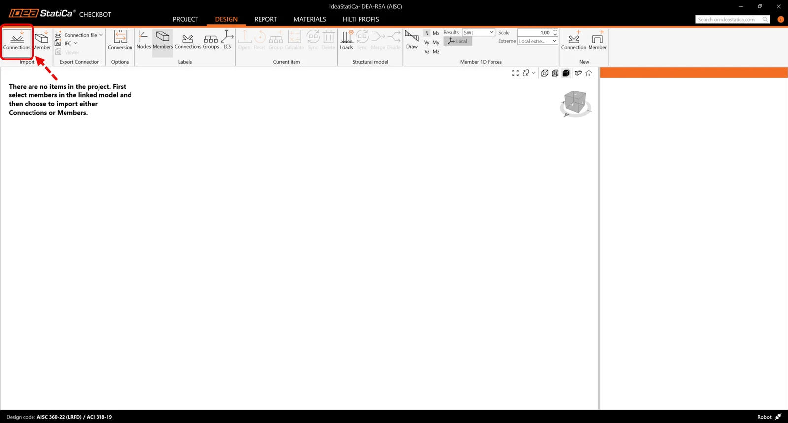
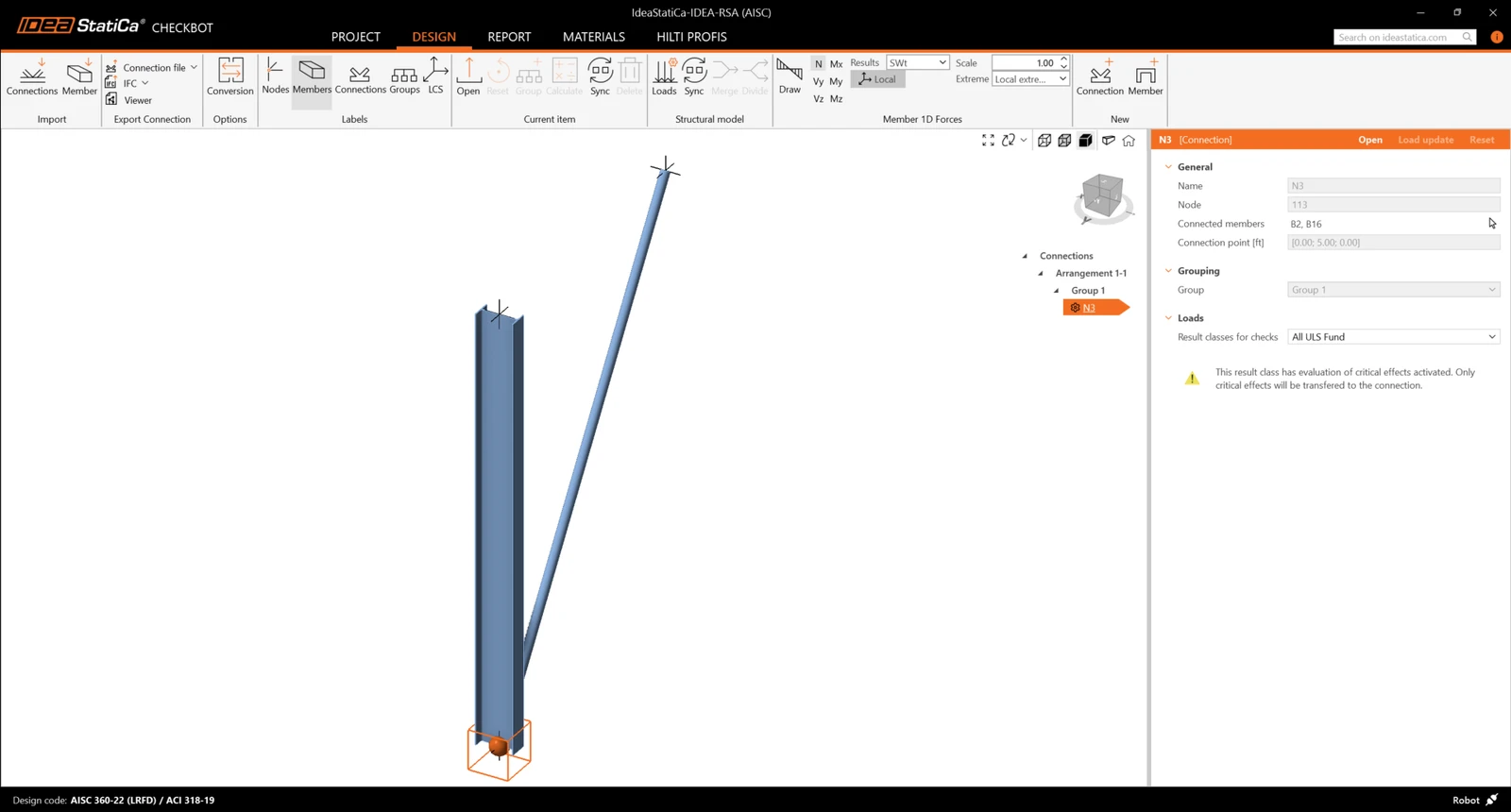
This will import the column and its load effects into Checkbot - with the same coordinates, orientations, and section sizes as per the FEA model.
Please note that your node and member numbering might be different.
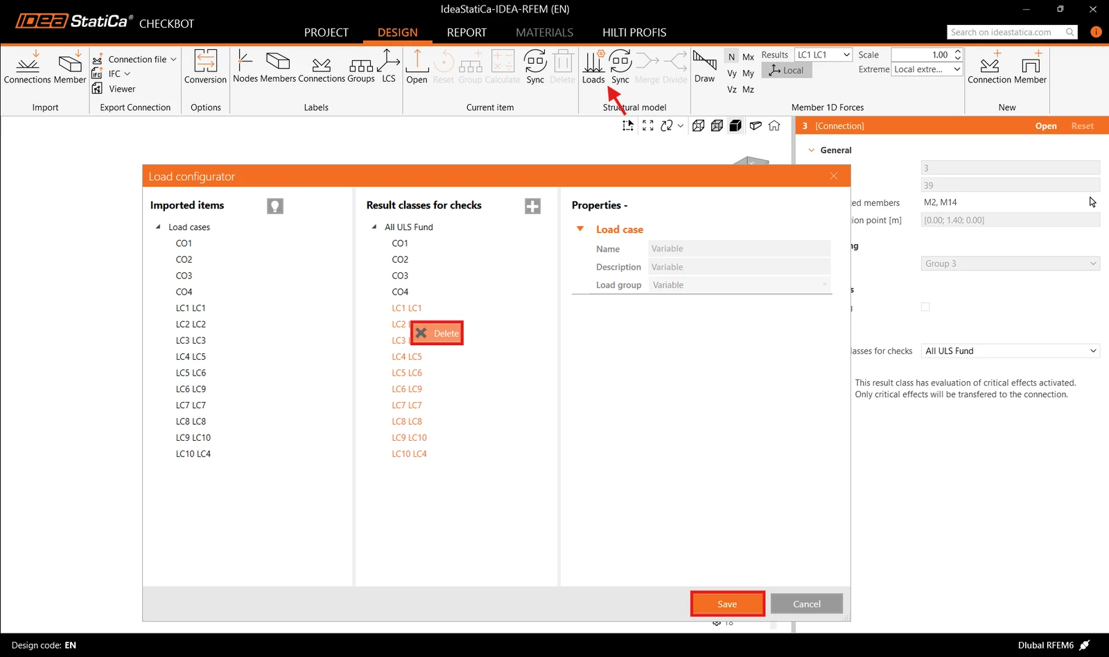
Before running the analysis, make sure to review the Result classes for checks and adjust the load cases accordingly. In the Load configurator dialog, you can see all imported load cases and load combinations on the left and the result classes used for checks in the middle. If some load cases are not relevant for your design verification, exclude them by right-clicking on the selected loads and removing them from the result classes list.
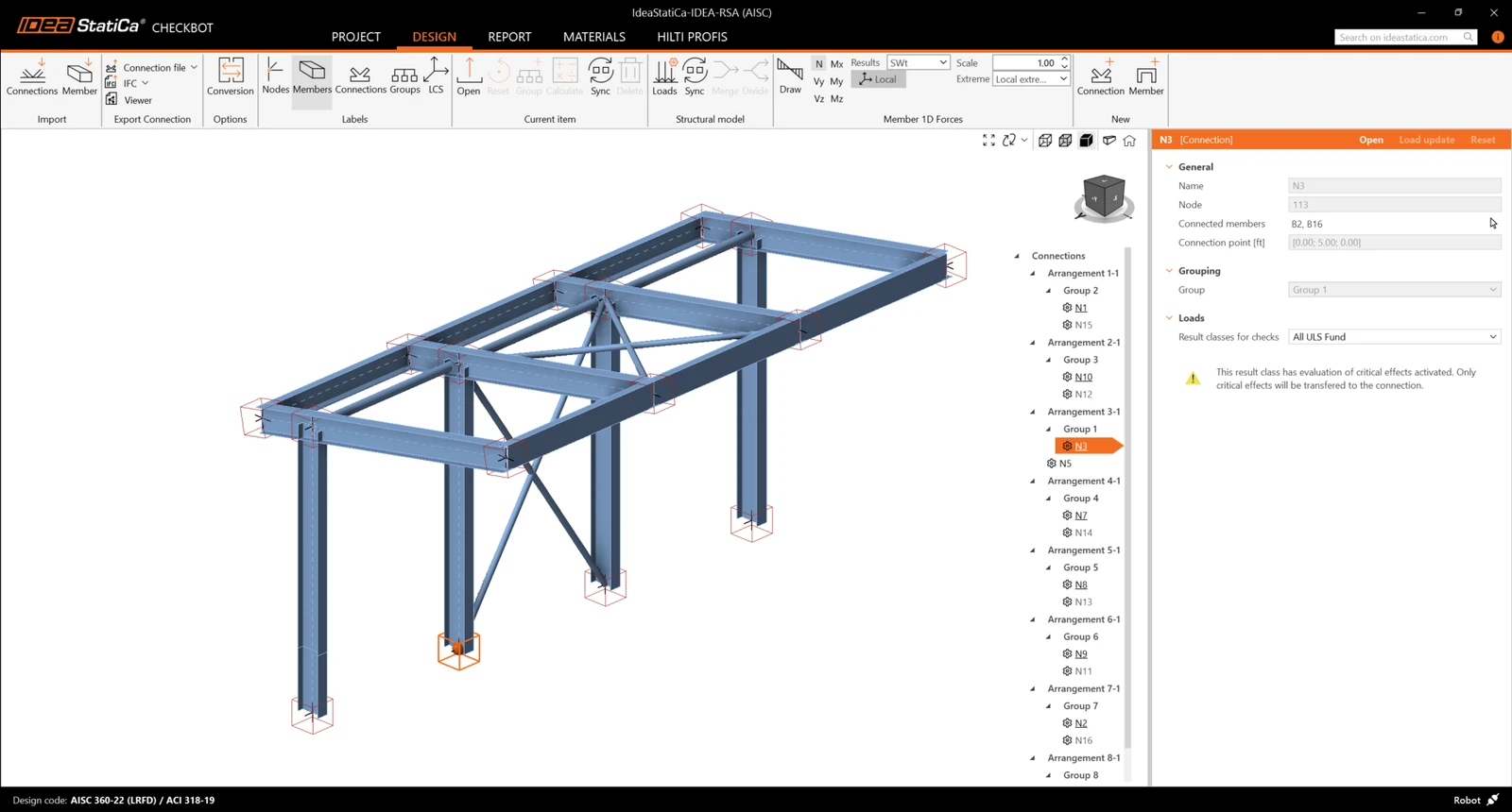
Please note the 3D workspace is designed to show an overview of the imported structure and not a detailed view of the actual connections. For more information on Checkbot, see here.
For several FEA solutions, you can also import multiple connections into Checkbot in the same manner as above. Instead of selecting one node and the connected members, you can select multiple nodes and members and import them all at once.
Geometry
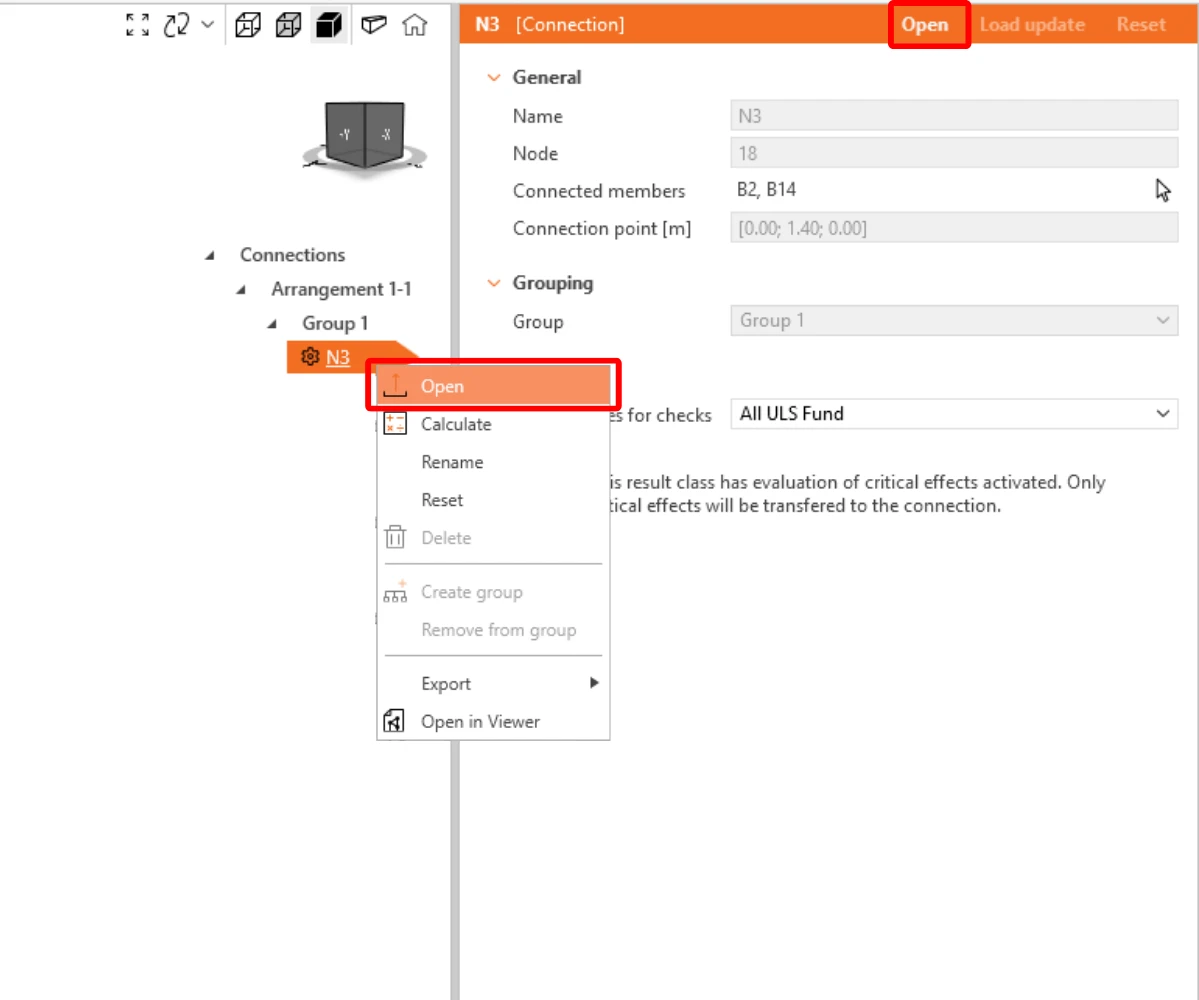
In the list of project items under Connections and with a connection highlighted in Checkbot you can either right-mouse click and select Open or click the ribbon command Open to start designing, code-checking, and reporting.
The settings of members are taken from the original FEA application. You can, however, change the section size of any member on the main Checkbot screen, but this will break the link with the FEA application in this session unless it's synchronized again.
The imported connection is opened in the IDEA StatiCa Connection application.
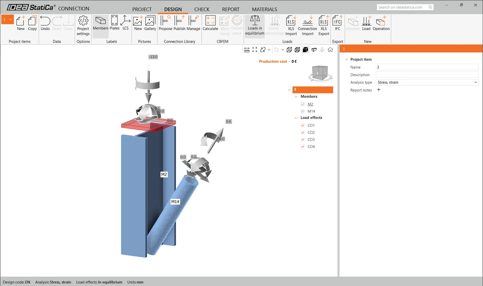
You may see none or different Load effects from your FEA solution, depending on how the load case combinations have been defined. By default, IDEA StatiCa will choose the most critical for code-checking purposes. (* Some BIM solutions are not able to store the load case combination results)
For more information on Load effects, see here.
Design
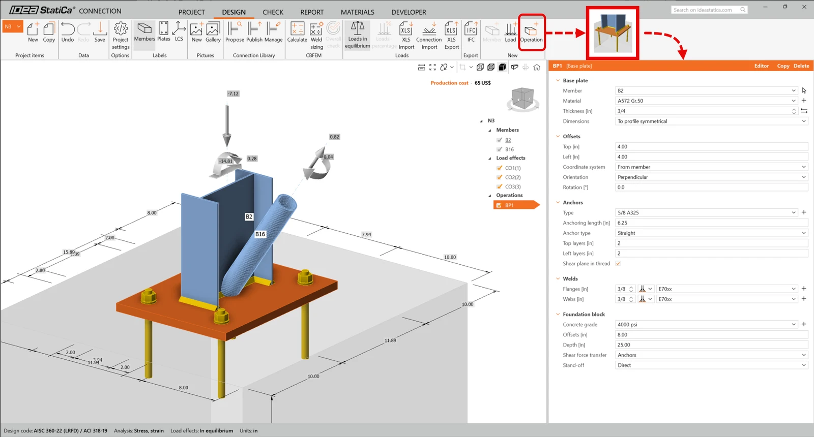
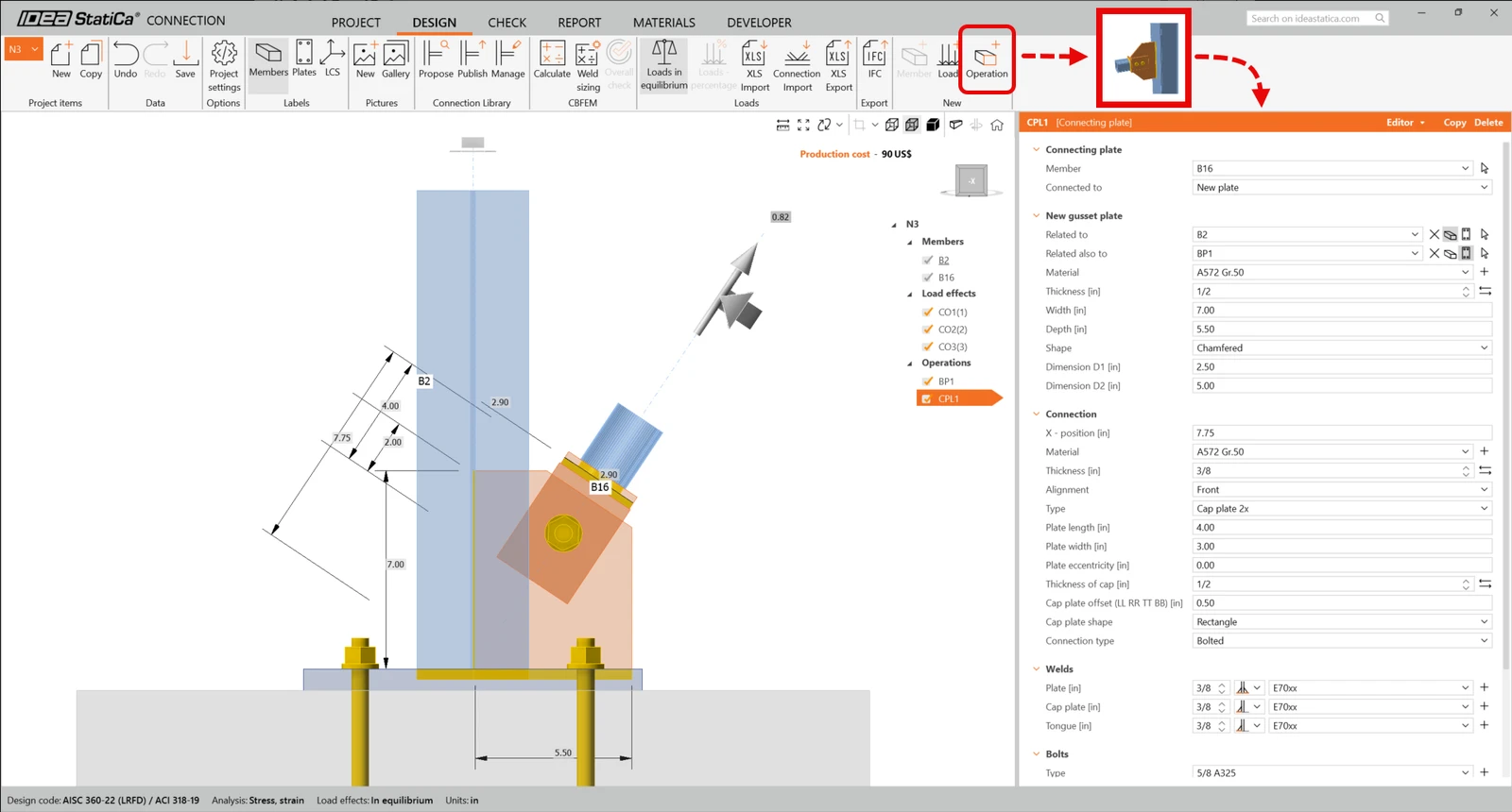
To create the base plate connection, we are going to use the manufacturing operations. On the upper ribbon select Operation, choose the Base plate and Connecting plate operations, and adjust the parameters as shown below:
Base plate
Connecting plate
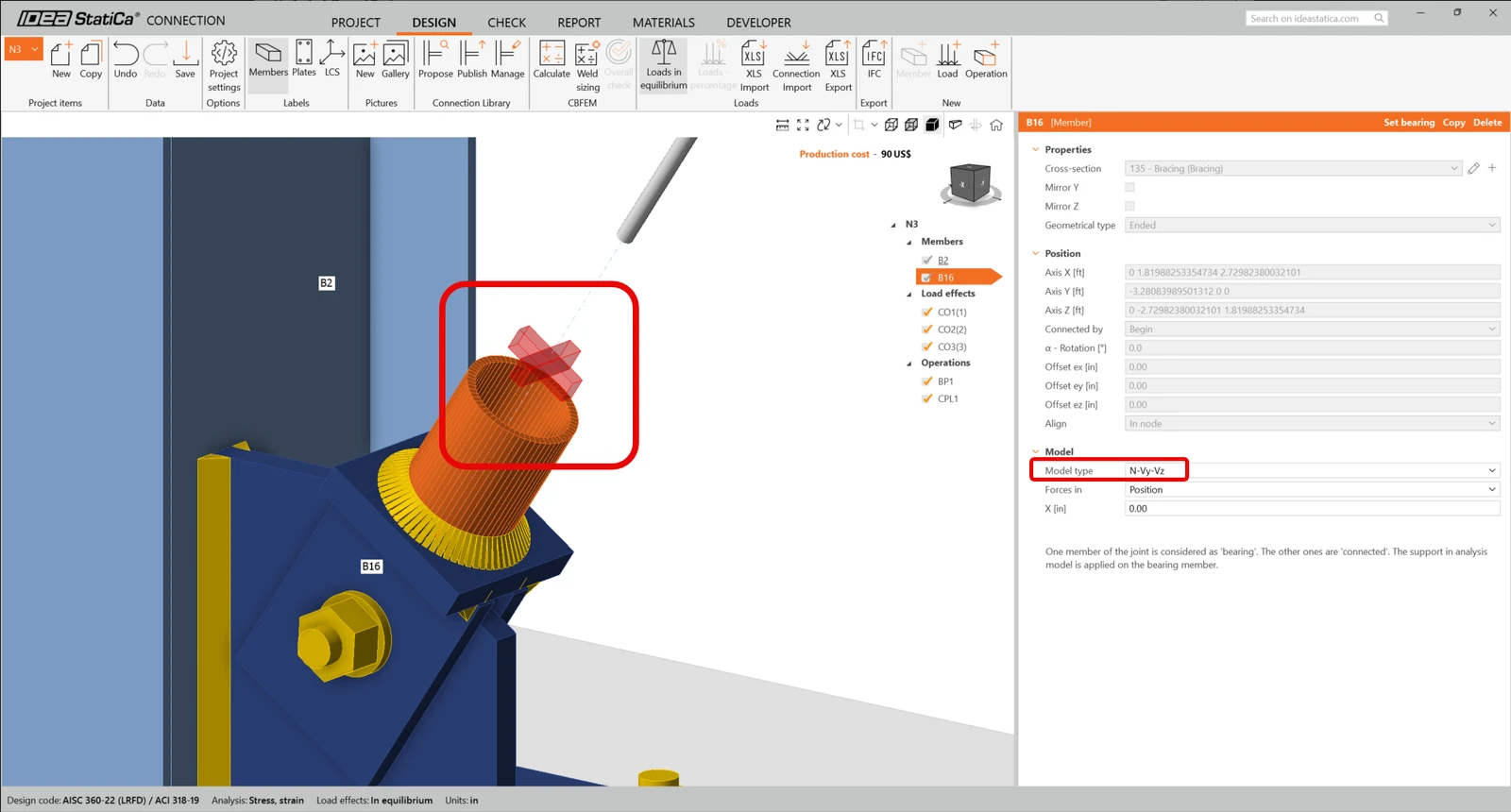
As we have connected the diagonal brace using a single bolt connection, we must also change the Model type of the brace member to N-Vy-Vz. Select the brace in the list of Members and modify the Model type in the drop-down list.
This is what the designed connection looks like.
Code check and Report
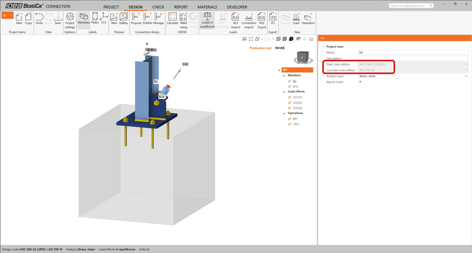
To run a code check, we must also make sure that the code is correct in IDEA StatiCa Connection. From the Design tab in the Connection label N3, ensure that LRFD 2022 is being used.
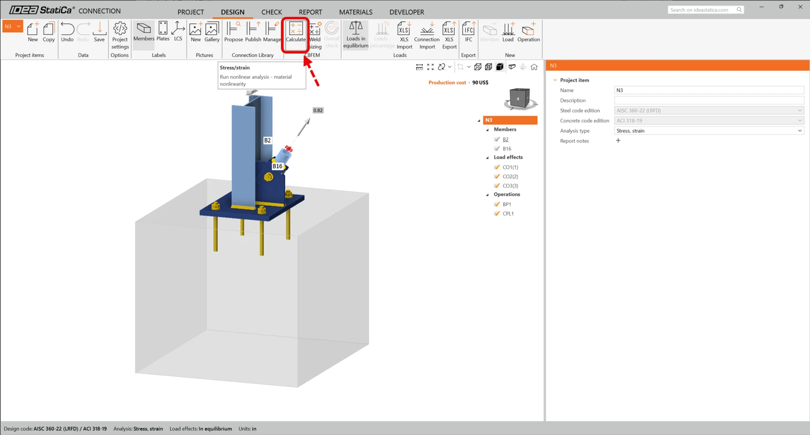
Now run a code check using the Calculate icon in the CBFEM panel from the top ribbon.
Within IDEA StatiCa Connection you can carry out many different types of analysis and code-checks. For more information please see here.
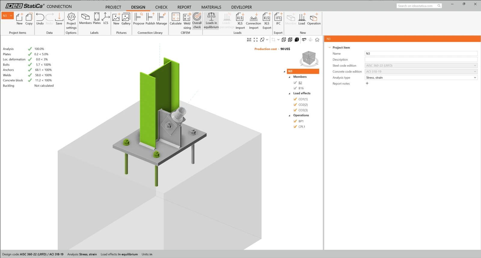
You will get the results of the nonlinear analysis.
Note: This part is common to multiple tutorials, so the results may vary depending on the software the project was imported from.
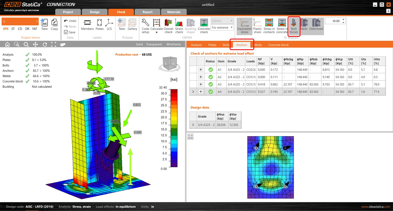
The detailed results for plates, bolts, welds, anchors can be displayed using the ribbon menu. In the image below the Deformed shape with Equivalent stress is being displayed.

You can go through the results on anchors as well.
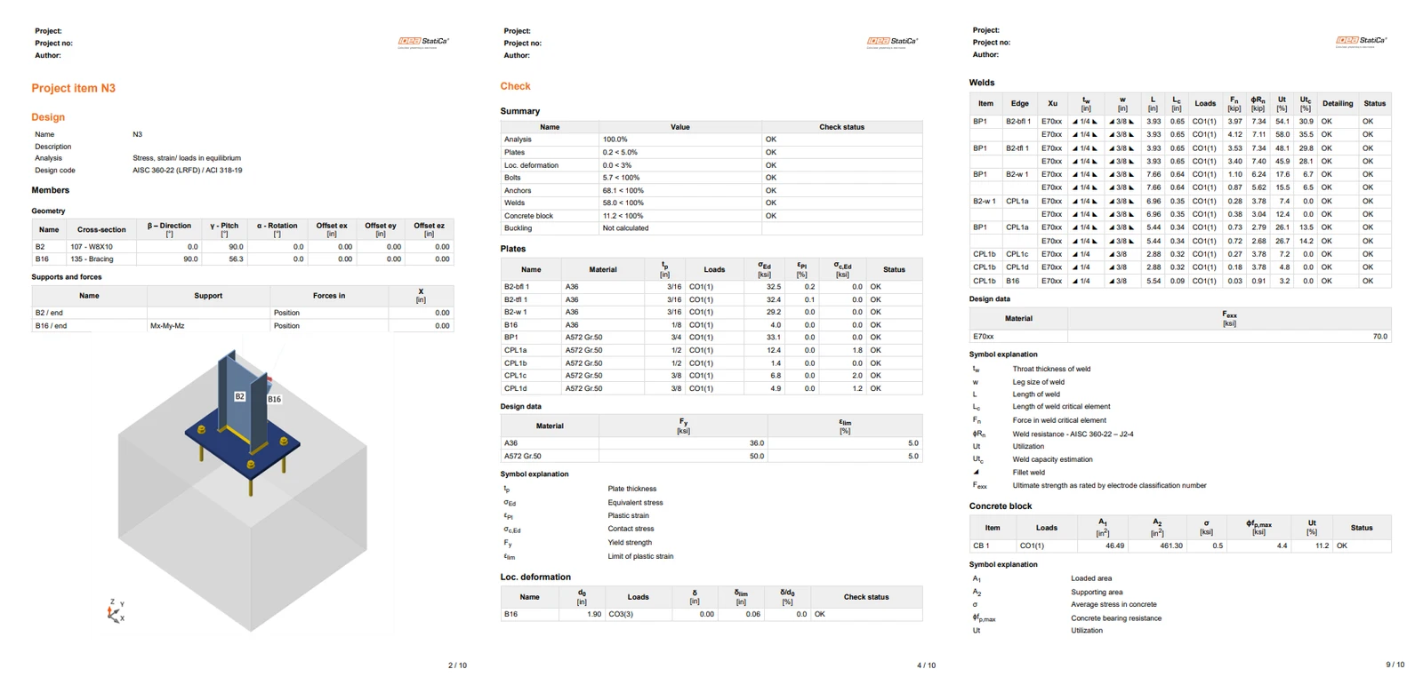
Once the code-check is finished, you can create the report containing results and diagrams for your connection model in the Report tab.
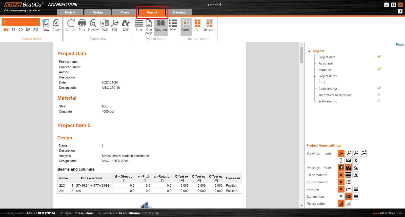
IDEA StatiCa offers a fully customizable report to print out or save in an editable format. For more information, please see here.
Save and exit this connection back to Checkbot.
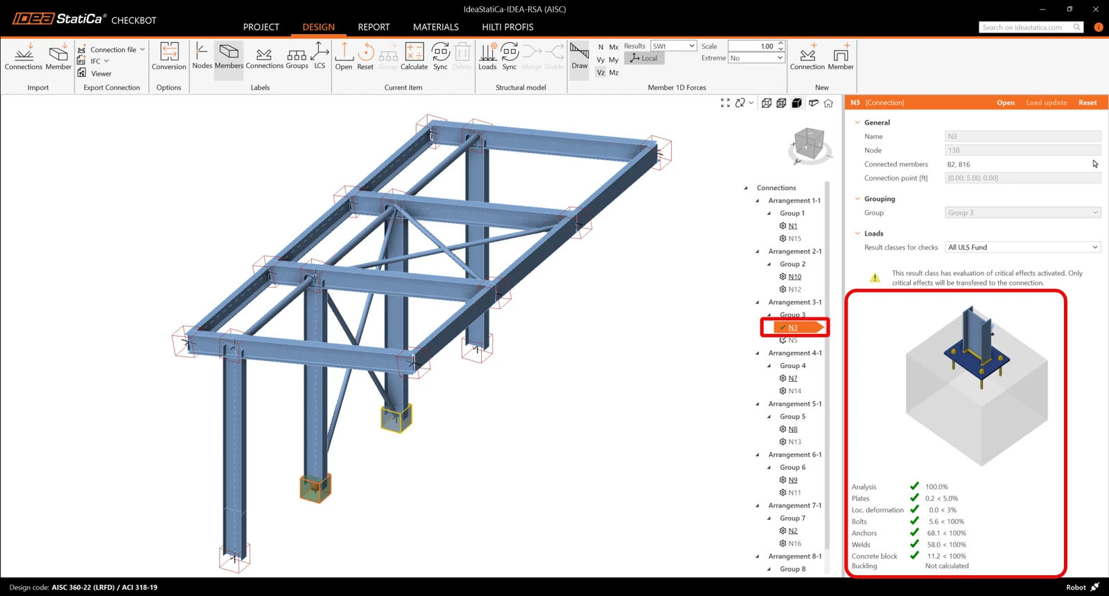
In Checkbot, you will see a green tick next to the connection. This means that the connection is valid and has passed all code-checks. In the Connection panel, you can also see a representation of the connection and a summary of the code-check results.
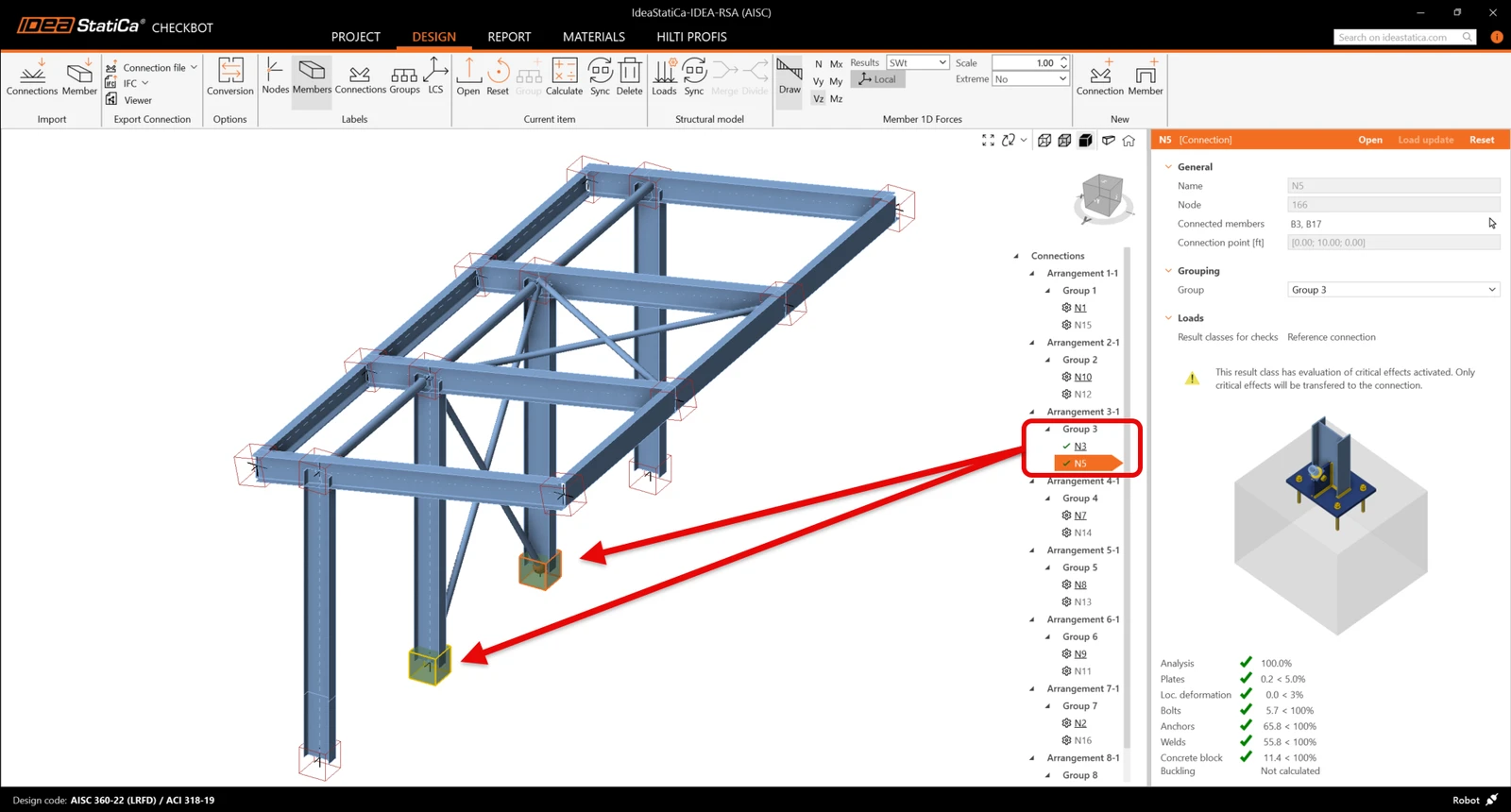
If multiple similar connections are present in Checkbot, they will be automatically grouped together. Users then have the option to batch designed the grouped connections.
In the example below, you can see that both baseplate connections, under group 3, have passed their respective code-checks while the remaining connections are yet to be validated.
Synchronize connections
Sometimes, there are changes to your FEA model, such as different member cross-section or increased load. These can be synchronized between Checkbot and the FEA model.
There are two possible alternatives:
- Synchronize the Current item (if one or more joints are selected)
- Synchronize the whole imported Structural model
To test this feature, you can change a member cross-section in your FEA application. Remember to re-analyze the FEA model to synchronize fresh results as well.
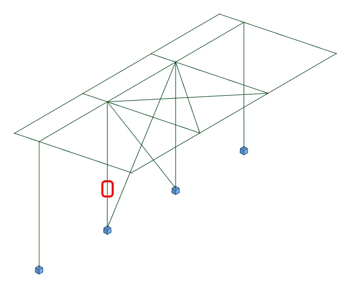
In Checkbot, select the designed connections (there may be more than one) and from the Current item panel select Sync.

The Checkbot project will be updated. The previously finished connection design is preserved, but the code-checks will be invalidated. You can see that the column is now updated - matching the change in the FEA model.
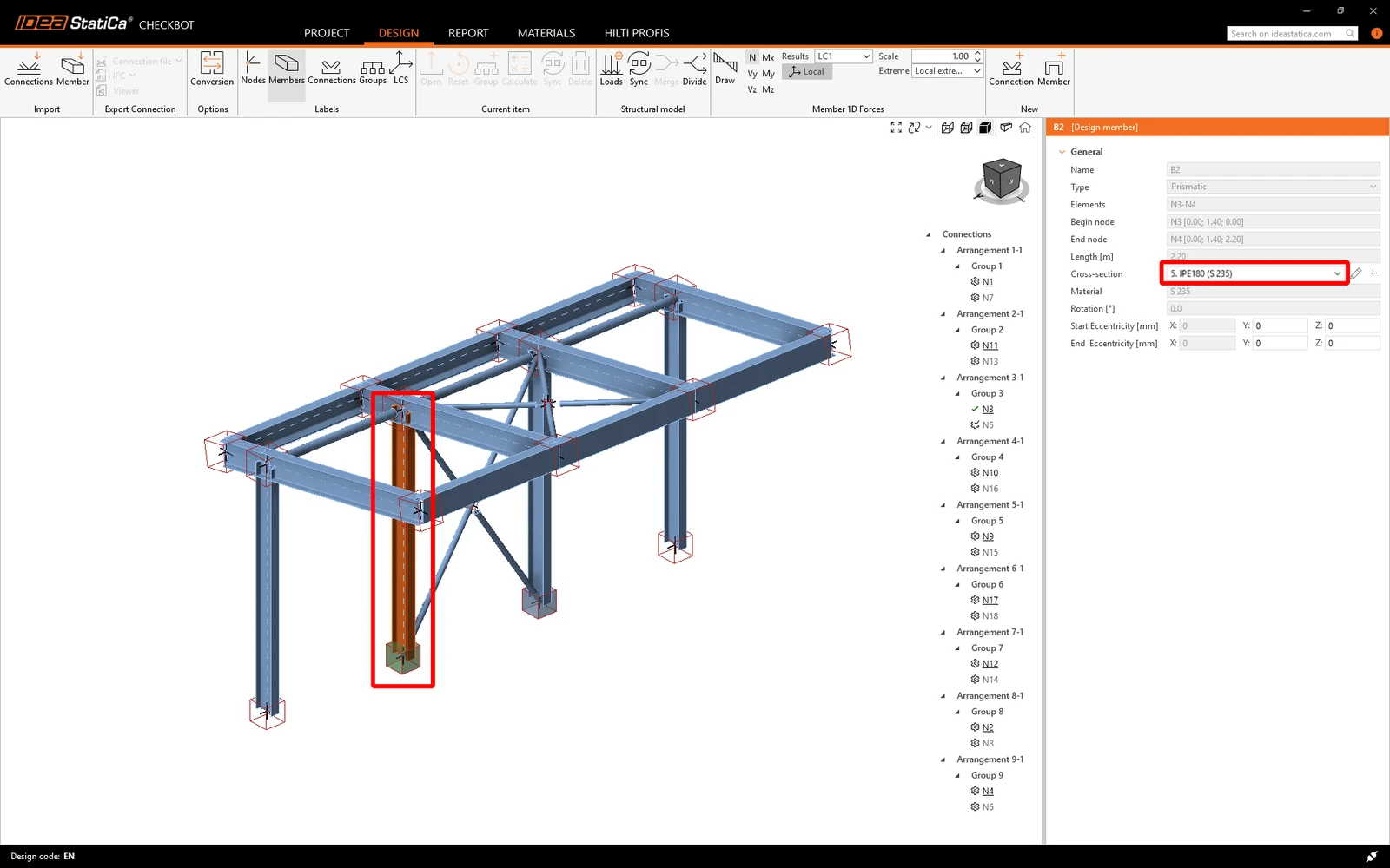
Simply code-check the highlighted connections again by selecting Calculate from the Current item panel.
If the connections do not give the desired results, then you can open them again to optimize the design (i.e. strengthen if they fail the code-check or lighten if the utilization is too low).
Bigger changes in the FEA model might require synchronization of the whole structural model in Checkbot, instead of just the current item.

You have successfully linked Robot Structural Analysis with IDEA StatiCa Connection via Checkbot. You have also designed, checked, and reported on a connection before incorporating changes made in the original FEA model back into IDEA StatiCa Connection.
Want to improve your skills? Visit our Campus
Learn how to use IDEA StatiCa effectively with our self-paced e-learning courses
Start learning
- Connection design
- Steel
- Tutorials
Bolted plate to plate connection design (AISC)
Read more
- Connection design
- Steel
- Tutorials
Structural design of a general 3D joint (AISC)
Read more
- Connection design
- Steel
- Blog post
The humble baseplate connection design
Read more
- Steel
- Connection design
- Webinar