Influence of temporary supports on bending moment diagrams for composite structures
Introduction
One might suggest why is the rapid increment of bending moment at the intermediate support when connecting together two precast beams by cast-in-situ slab and diaphragms. The expecting behavior was that the bending moment occurs at the intermediate support in some time due to creep of the concrete but no immediately after compositing of the precast beams and cast-in-situ parts. Let us look at this problem in more detail and consider the various layout of temporary supports and their influence on the distribution of internal forces.
Structure description
In order to explain high bending moment occurrence at the support of a continuous beam, two cases were analyzed in software IDEA StatiCa Beam and midas Civil. Let's consider two precast beams composite with cast-in-situ reinforced concrete slab and diaphragm at the support. The concrete class is the same for both parts of a composite cross-section, C45/55. The cross-sections shapes are as follows:
Composite section:
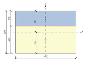
Diaphragm at the support:

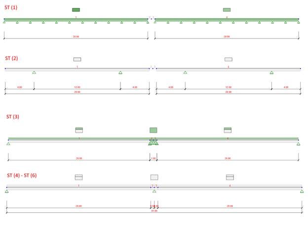
Static scheme changes in time. For each case, various support layout is considered. The construction process is identical, though. Precast beam fabrication, storage yard, precast beam mounting on the temporary supports at the site, and consequent compositing with cast-in-situ slab and diaphragm. The position of final supports is the same for both cases, as well as the history of loads.
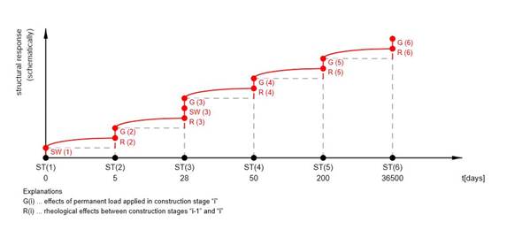
The load history for both cases:
Construction stages for case A (temporary supports when casting the slab):
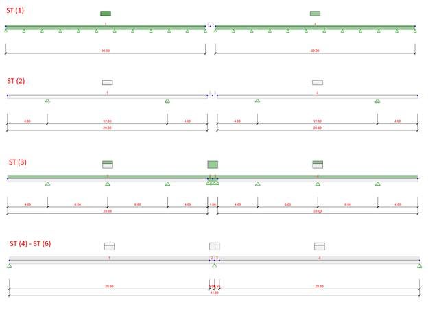
Construction stages for case B (without additional temporary supports when casting the slab):
Comparison of midas Civil & IDEA StatiCa Beam
During the comparison, we focused on the bending moments at the support and midspan in particular construction stage for both cases.
Case A
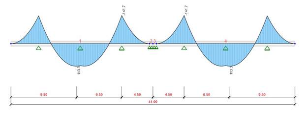
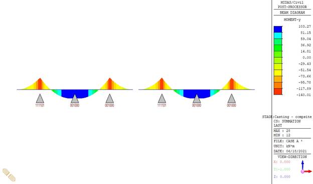
Construction stage 3:
Precast beam supported by the temporary supports, subjected to self-weight and wet concrete of RC slab, including creep and shrinkage.
Bending moment diagram – IDEA StatiCa Beam
Bending moment diagram – midas Civil
Construction stage 4:
Precast beams are composite with the slab, the composite section resists to self-weight only, final supports stage, including creep and shrinkage.
Bending moment diagram – IDEA StatiCa Beam

Bending moment diagram – midas Civil

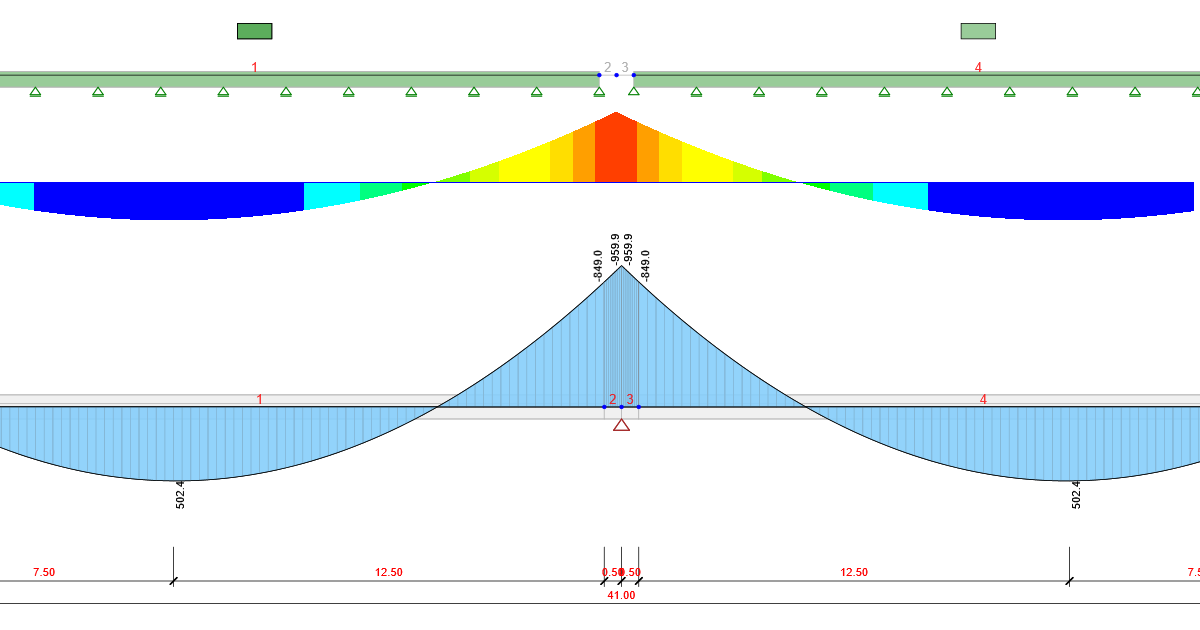
Construction stage 6:
Structure at time 100 years, subjected to self-weight only, including creep and shrinkage.
Bending moment diagram – IDEA StatiCa Beam

Bending moment diagram – midas Civil

Case B
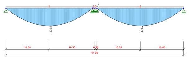
Construction stage 3:
The precast beam is supported by the final supports, subjected to self-weight and wet concrete of RC slab, including creep and shrinkage.
Bending moment diagram – IDEA StatiCa Beam
Bending moment diagram – midas Civil

Construction stage 4:
Precast beams are composite with the slab, the composite section resists to self-weight only, final supports stage, including creep and shrinkage.
Bending moment diagram – IDEA StatiCa Beam

Bending moment diagram – midas Civil
Construction stage 6:
Structure at time 100 years, subjected to self-weight only, including creep and shrinkage.
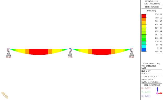
Bending moment diagram – IDEA StatiCa Beam

Bending moment diagram – midas Civil

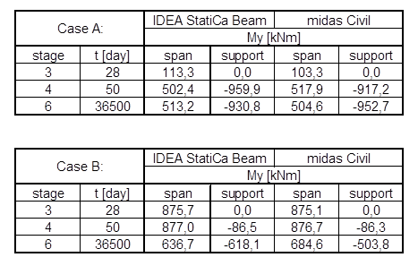
The outputs from IDEA StatiCa Beam and midas Civil were well-arranged into a table:
Conclusion
The table above shows that the results from the different software are more or less the same. The deviations in the results are due to the fact that the notational size height h0 before and after compositing of the structure is not distinguished in midas Civil.
The user has to specify the cross-section parameters corresponding to the stage either before or after compositing the precast concrete beams with the reinforced concrete cast-in-situ slab, for each part of the cross-section separately. Whereas in IDEA StatiCa Beam the stage before compositing is taken into account, i.e. the circumference of the drying part of the section corresponds to the circumference of the whole cross-section of the precast beam, and after compositing. i.e. the circumference of the drying part of the precast beam is reduced by the length of the construction joint between the precast beam and the cast-in-situ slab. The rapid increase in bending moment over the middle (final) support is attributed to the chosen arrangement of temporary supports. It is the temporary supports that eliminate the effects of construction stages, and thus we obtain bending moment diagrams that are close to those of a structure as it would be built by a full staging method.
In case B, where no intermediate, temporary support is considered, the negative effect of construction stages can be observed as several times the static scheme was changed and due to different moment diagrams.
The purpose of this study was to verify the accuracy of the results provided by IDEA StatiCa Beam and midas Civil. Since the same behavior of the structure was confirmed in both independent software, the results in IDEA StatiCa Beam can be declared correct.
Attached Downloads
- Composite beams - comparison with midas Civil.zip (ZIP, 9.1 MB)