What does the code say about a slender column subjected to compression and bending in both directions? How should engineers safely design and check such a column? You can use simplified methods, which may lead to a conservative design due to providing greater second-order effects. Or you can go for a more accurate approach, a general method based on nonlinear analysis. But the workflows for the general method are not described in the code. The code expects the engineers to cope.
You can now analyze slender columns via a more advanced method using both geometric and material nonlinear analysis in IDEA StatiCa. A new type of analysis allows the design and code-check of members subjected to normal force and bending moments for ultimate and serviceability limit states. The checks are performed at the comparison of stresses and strains with the limit values given by the standard, EN 1992-1-1.
Follow an easy four-step workflow to make the design and check of slender columns more understandable and engaging:
- Create geometry of the structure, including boundaries and reinforcement
- Subject analyzed and related members to the load effects
- Nonlinear analysis and the assessment
- Report with all important figures, results and checks
Geometry
Loads
Analysis
Report
Analysis types
The structure's geometry is composed of the members, boundary conditions and results. They can be created in the Member application or imported from 3rd party software (like Robot Structural Analysis, SAP200, RFEM, etc.). After that, you add reinforcement to the member and start analyzing using the results obtained from the structural analysis. For slender columns, where linear analysis is insufficient, use nonlinear analysis which is available under the GMNA button.
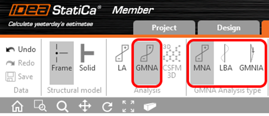
The GMNA itself consists of three analysis types:
- Materially nonlinear analysis (MNA)
- Linear buckling analysis (LBA)
- Geometrically and Materially Nonlinear Analysis with Imperfections (GMNIA)
What are all these analyses for? What is an engineer supposed to do with it?
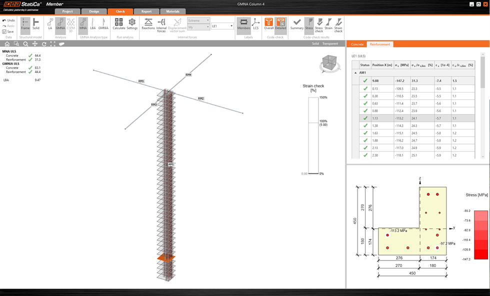
Materially nonlinear analysis (MNA)
You may proceed as the buttons in the ribbon suggest. First, material nonlinear analysis (MNA) is performed. An analyzed member is automatically divided into several sections where the stresses and strains are evaluated for each concrete fiber and reinforcement bar. Then, the provided values are checked with the limit values defined by the code.
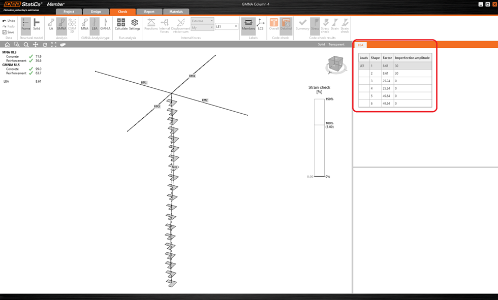
Linear buckling analysis (LBA)
If it is not enough to consider only material nonlinearity and it is also necessary to consider geometric one then in that case, it is time to use the linear buckling analysis (LBA), whose outputs are eigenmodes and critical loads of the analyzed member. This analysis helps an engineer determine the theoretical loss of stability of a structure subjected to acting loads. It would not be safe to consider only the theoretical buckling shape of the structure since there are initial imperfections. That is why the result table enables the definition of imperfection amplitude for each eigenmode. The imperfection shall be defined by the engineer based on the experience or code recommendation.
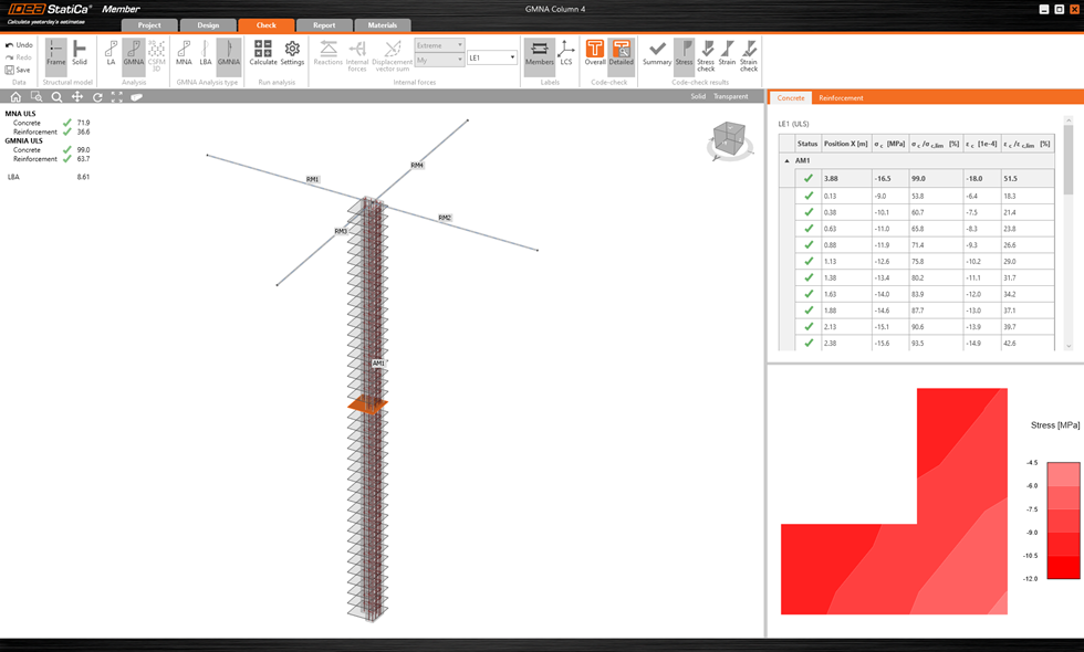
Geometrically and Materially Nonlinear Analysis with Imperfections (GMNIA)
Once the imperfection is defined, it is automatically proportionally applied to the member, then you can perform the last analysis type – geometrical and material nonlinear analysis with imperfections (GMNIA). Similarly, as the first analysis (MNA), the member is divided into sections where the stresses and strains for each concrete fiber and reinforcement bar are evaluated, taking into account material and geometrical nonlinearity resulting from a buckling shape with imperfections.
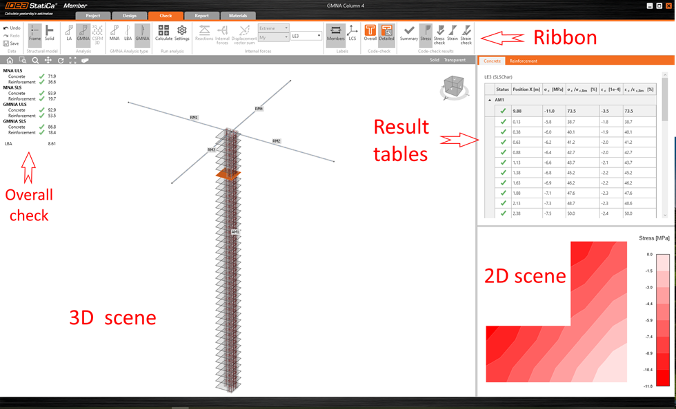
User interface tips for Member application
All analysis outputs are available in the Check tab, where the ribbon was reorganized and expanded by several new buttons. The graphic result interpretation is displayed in the main 3D scene. At the same time, the calculated values and checks are listed in the result tables together with the corresponding detailed or sectional results in the 2D scene.
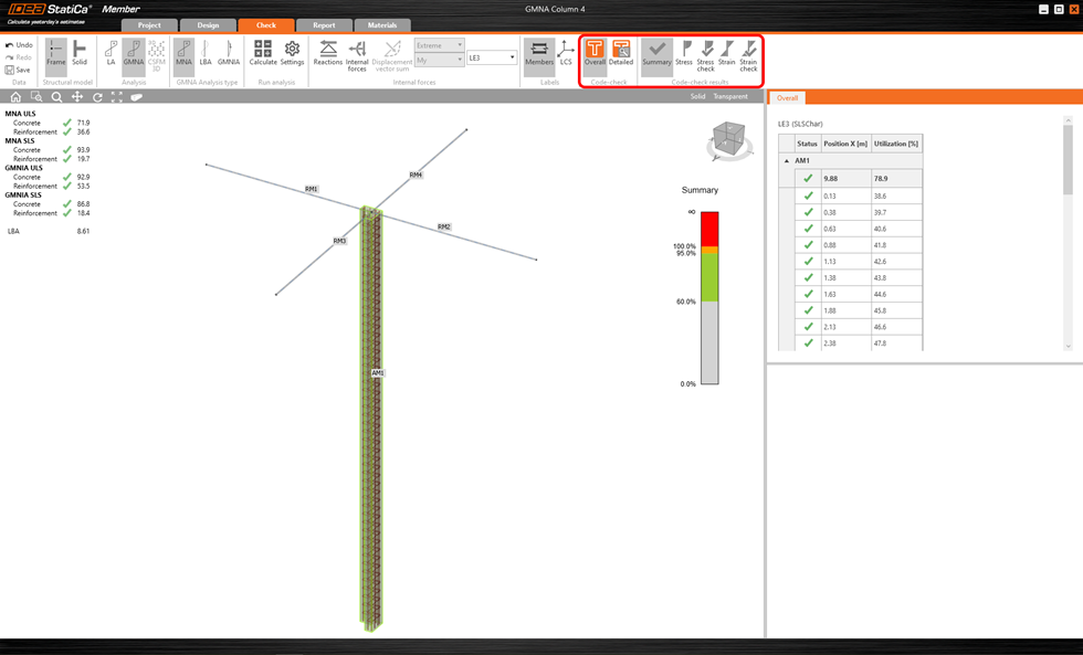
Users can display Overall or Detailed (sectional) results. The Overall code-check shows a summary of all the results available in the project. The user can immediately see whether the structure satisfies or not the particular code-checks.
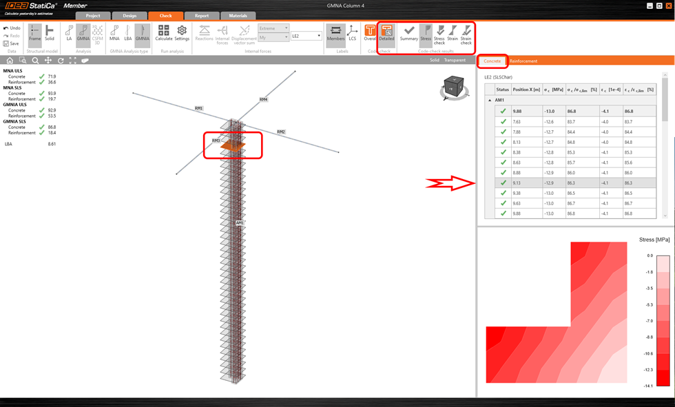
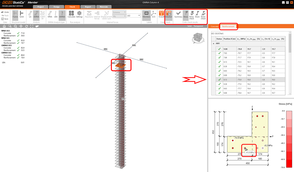
If the user selects the particular section in the 3D scene then the corresponding results are highlighted in the result table, and the detailed view of the selected section is displayed in the 2D scene. Calculated stresses, strains, and checks are available for each section for concrete and reinforcement parts in particular tabs.
Design and check of slender columns in Member for concrete is available in Concrete Expert, Concrete Enhanced, Prestressing Expert and Prestressing Enhanced edition of IDEA StatiCa.