Branch/Through-Plate Connection with Rectangular HSS (AISC)
The example is taken from AISC Design Guide 24 - Example 7.1:
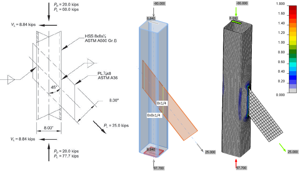
The welded HSS connection is subject to the plate axial tension force indicated produced by a diagonal bracing member. The column is subject to axial compression dead and live loads of PD = 20.0 kips and PL = 60.0 kips. Determine if the connection is adequate as a branch-plate connection or if a through-plate connection is required. Note that the connection is checked under the action of the plate force component normal to the column, as this has the dominant effect.
Results in Design Guide
The column is from steel grade ASTM A500 Gr. B and the plate from steel grade A36.
The available strength for the limit state of HSS chord wall plastification is:
- 23.1 kips < 40 kips (LRFD)
- 12.5 kips < 25 kips (ASD)
Treating the connection as a branch-plate connection is not adequate.
Chord wall plastification assuming a through-plate connection:
- 46.2 kips > 40 kips (LRFD)
- 30.4 kips > 25 kips (ASD)
The connection will be adequate.
Nominal strength for the limit state of tension yielding on the plate:
- 64.8 kips > 40 kips (LRFD)
- 43.1 kips > 25 kips (ASD)
IDEA StatiCa Connection
IDEA StatiCa uses geometrically and materially nonlinear analysis for the check of hollow section joints. The load resistance is determined by four criteria:
- reaching the capacity of any code check of component (weld, bolt etc.)
- reaching 5% plastic strain limit of plates
- end of convergence (meaning buckling failure)
- reaching 3% cross-section deformation limit
For further information about analysis of hollow section joints see Joints of hollow section cross-section members.
Loads in equilibrium is used to allow loading of the column with a compressive force.
The results are as follows:

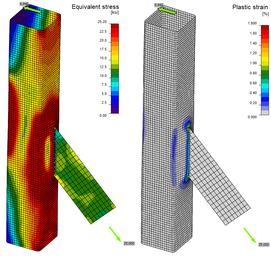
By overloading the joint and selecting "Stop at limit strain" function in Code setup, the load resistance may be determined. It is equal to 27.35 kips for ASD and 39.65 kips for LRFD. The cross-section deformation is equal to 2.3 % and is nearing the limit. The connection fails by reaching 5% plastic limit strain of the hollow section.
Comparison
The results according to IDEA StatiCa Connection are slightly more conservative. One of the main reasons is the safety (resistance) factor which is used \(\Omega=1.67\) and \(\phi=0.9\) for all plates in IDEA Connection. It is not possible to use different safety (resistance) factors in one model.