


Introduction
Buckling Restrained Braced Frames (BRBFs) are a category of concentrically braced frames specifically engineered for enhanced seismic performance. They incorporate a unique brace component, known as the Buckling Restrained Brace (BRB), which is designed to yield in both tension and compression without experiencing buckling. This behavior enables BRBFs to combine high elastic stiffness with exceptional ductility, as recognized in the provisions of AISC 341-16 (2016).
This verification example was prepared in a joint project between the University of Illinois at Chicago and IDEA StatiCa. This work was conducted by:

Goal of the Project
The primary objective of this project was to evaluate the behavior of seismic bracing connections using the IDEA StatiCa software package, based on capacity design principles. In this approach, the core plate of the BRB is treated as a “fuse” element in BRBF systems and is expected to undergo significant inelastic deformation under governing seismic load cases.
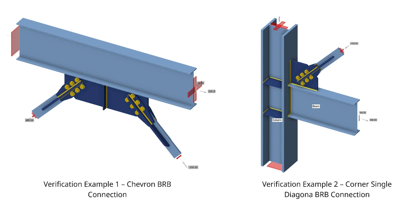
For the presented study, two types of BRBF connections—Chevron and Corner connections—commonly used in BRBF systems, were analyzed using the Component-Based Finite Element Method (CBFEM) in IDEA StatiCa. The results were then verified against calculations performed using AISC standards.
Verification Project Structure
- For each connection type, a baseline model was created, matching the design details specified in AISC 341-16.
- Design checks were performed in accordance with the requirements outlined in AISC 341-16 and AISC 360-16, considering only the connection-level limit states.
- The same specimens were modeled and analyzed in IDEA StatiCa to evaluate their design resistance and failure modes.
- Capacity design analysis was performed using IDEA StatiCa, and the results from CBFEM were compared with those obtained using traditional calculations based on AISC provisions.
- Several connection limit states—such as tensile yielding, block shear rupture of gusset plates, bolt shear, bolt bearing, and bolt tear-out—were evaluated using CBFEM and compared with AISC results.
- The comparison between IDEA StatiCa and AISC design calculations was assessed, and key findings and recommendations were developed.
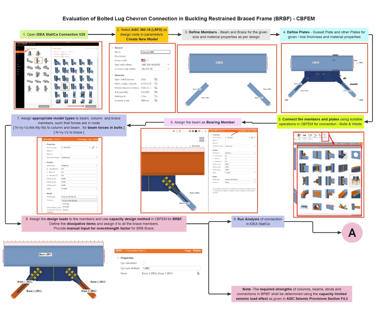
BRBF - Part 1
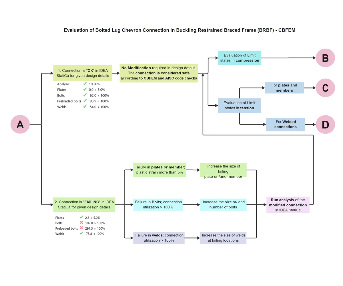
BRBF - Part 2
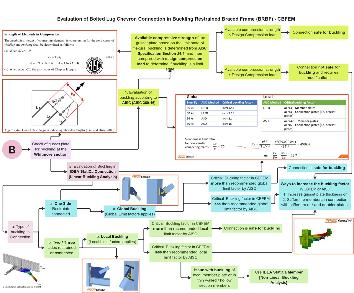
BRBF - Part 3
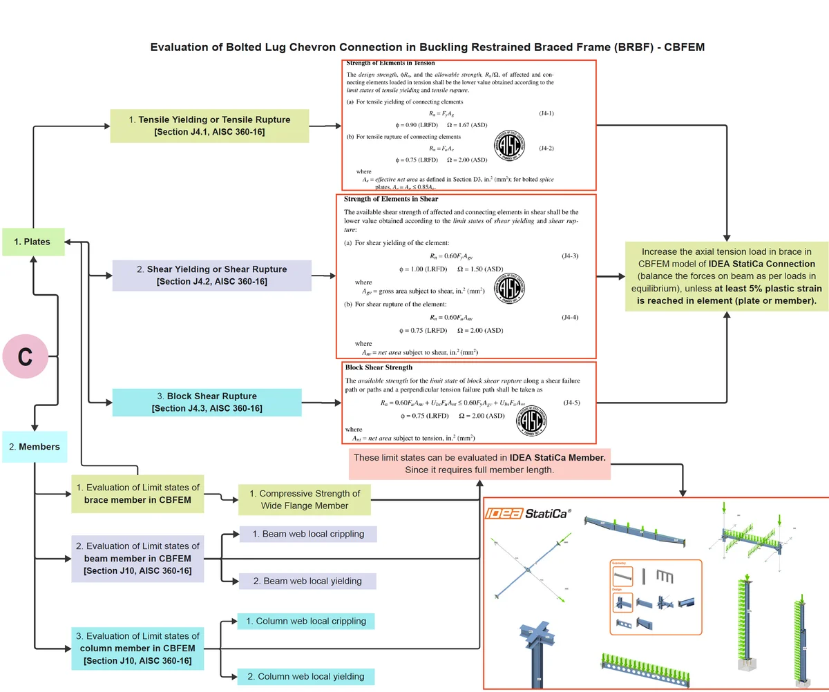
BRBF - Part 4
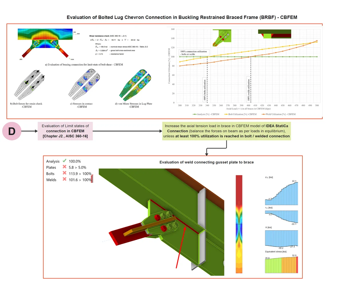
BRBF - Part 5
Summary
The study conducted at UIC demonstrated that the CBFEM approach implemented in IDEA StatiCa is reliable for evaluating seismic bracing connections in BRBFs. The software was able to closely capture most of the relevant connection-level limit states. The results showed an average deviation of approximately 2% to 5% when compared to AISC-based calculations, with CBFEM results generally slightly on the conservative (higher) side.
Overall, it is concluded that IDEA StatiCa is a dependable and insightful tool for analyzing and designing seismic bracing connections in BRBF systems. Its capacity to model nonlinear behavior, visualize local limit states, and support performance-based design makes it a valuable asset for modern structural engineering practice.
Summary of Results
Verification Example 1 – Chevron Connection
1. Evaluation of Limit State for Tension Load in Brace
| Sr No | Limit State of | AISC (kips) | CBFEM (kips) | ∆AISC_CBFEM (%) |
| 1 | Tensile Yielding of Gusset Plate | 450 | 465 | 3% |
| 2 | Block Shear Rupture of Gusset Plate | 480 | 490 | 1% |
| 3 | Bolt Shear | 51 | 51 | 0% |
| 4 | Bolt Bearing | 56.75 | 56.75 | 0% |
| 5 | Bolt Tearout | OK | OK | N.A |
2. Comparison of weld sizes as per AISC and CBFEM
| Sr No. | Pbrace (kips) | Check of weld connecting | Required ‘16ths weld size (in) | |
| AISC | CBFEM | |||
| 1 | 405 | Gusset plate to beam bottom flange | 5/16 | 5/16 |
| 2 | 510 | Gusset plate to stiffener plate | ¼ | ¼ |
| 3 | 560 | Gusset plate to lug plate | 3/8 | 3/8 |
where, Pbrace is axial load in brace for which weld percentage utilization is 100% in CBFEM.
Verification Example 2 – Corner Connection
1. Evaluation of Limit State for Tension Load in Brace
| Sr No | Limit State of | AISC (kips) | CBFEM (kips) | ∆AISC_CBFEM (%) |
| 1 | Tensile Yielding of Gusset Plate | 450 | 476 | 6% |
| 2 | Block Shear Rupture of Gusset Plate | 480 | 485 | 1% |
| 3 | Bolt Shear | 51 | 51 | 0% |
| 4 | Bolt Bearing | 61 | 61 | 0% |
| 5 | Bolt Tearout | OK | OK | N.A |
2. Comparison of weld sizes as per AISC and CBFEM
| Sr No. | Pbrace (kips) | Check of weld connecting | Required ‘16ths weld size (in) | |
| AISC | CBFEM | |||
| 1 | 505 | Gusset plate to beam top flange | 5/16 | 5/16 |
| 2 | 530 | Gusset plate to column | 5/16 | 5/16 |
| 3 | 555 | Gusset plate to lug plate | 3/8 | 3/8 |
where, Pbrace is axial load in brace for which weld percentage utilization is 100% in CBFEM.
Read the full study examples:
References
AISC 341. (2016). Seismic Design Manual. American Institute of Steel Construction, Chicago, Illinois.
AISC 360. (2016). Specification for Structural Steel Buildings. American Institute of Steel Construction, Chicago, Illinois.
IDEA StatiCa. (n.d.). IDEA StatiCa Support center- FAQ. https://www.ideastatica.com/support-center-faq
Dowswell, Bo. (2006). Effective Length Factors for Gusset Plate Buckling | American Institute of Steel Construction. Https://Www.Aisc.Org/Effective-Length-Factors-for-Gusset-Plate-Buckling. https://www.aisc.org/Effective-Length-Factors-for-Gusset-Plate-Buckling