
Solution method and load-control algorithm
A standard full Newton-Raphson (NR) algorithm is used to find the solution to a non-linear FEM problem.
Generally, the NR algorithm does not often converge when the full load is applied in a single step. A usual approach, which is also used here, is to apply the load sequentially in multiple increments and use the result from the previous load increment to start the Newton solution of a subsequent one. For this purpose, a load control algorithm was implemented on top of the Newton-Raphson. In the case that the NR iterations do not converge, the current load increment is reduced to half its value, and the NR iterations are retried.
A second purpose of the load-control algorithm is to find the critical load, which corresponds to certain “stop criteria” – specifically the maximum strain in concrete, the maximum slip in bond elements, the maximum displacement in anchorage elements, and the maximum strain in reinforcing bars. The critical load is found using the bisection method. In the case that the stop criterion is exceeded anywhere in the model, the results of the last load increment are discarded, and a new increment of half the size of the previous one is calculated. This process is repeated until the critical load is found with a certain error tolerance.
For concrete, the stop criterion was set to a 5% strain in compression (i.e., around an order of magnitude larger than the actual failure strain of concrete) and 7% in tension at the integration points of shell elements. In tension, the value was set to allow for the limit strain in reinforcement, which is usually around 5% without accounting for tension stiffening, to be reached first. In compression, the value was chosen from among several alternatives as one that is large enough for the effects of crushing to be visible in the results, but small enough so as not to cause too many problems with numerical stability.
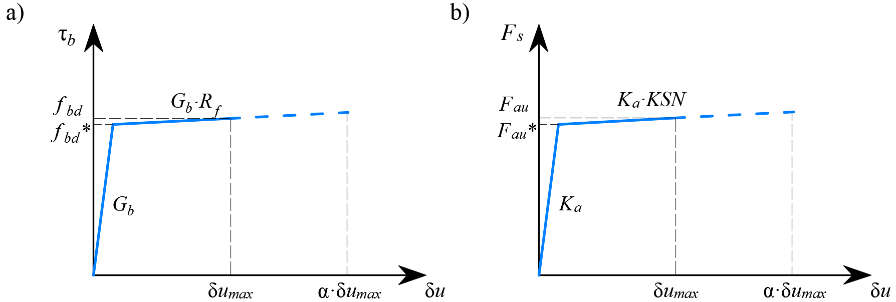
\[ \textsf{\textit{\footnotesize{Fig. 17\qquad Constitutive relationship of bond and anchorage elements used for anchorage length verification:}}}\]
\[ \textsf{\textit{\footnotesize{(a) bond shear stress slip response of a bond element; (b) force-displacement response of an anchorage element.}}}\]
For reinforcement, the stop criterion is defined in terms of stresses. Since stresses at the crack are modeled, the criterion in tension corresponds to the reinforcement tensile strength accounting for the safety coefficient. The same value is used for the criterion in compression.
The stop criterion in bond elements and anchorage springs is α·δumax, where δumax is the maximal slip used in code checks and α = 10.