
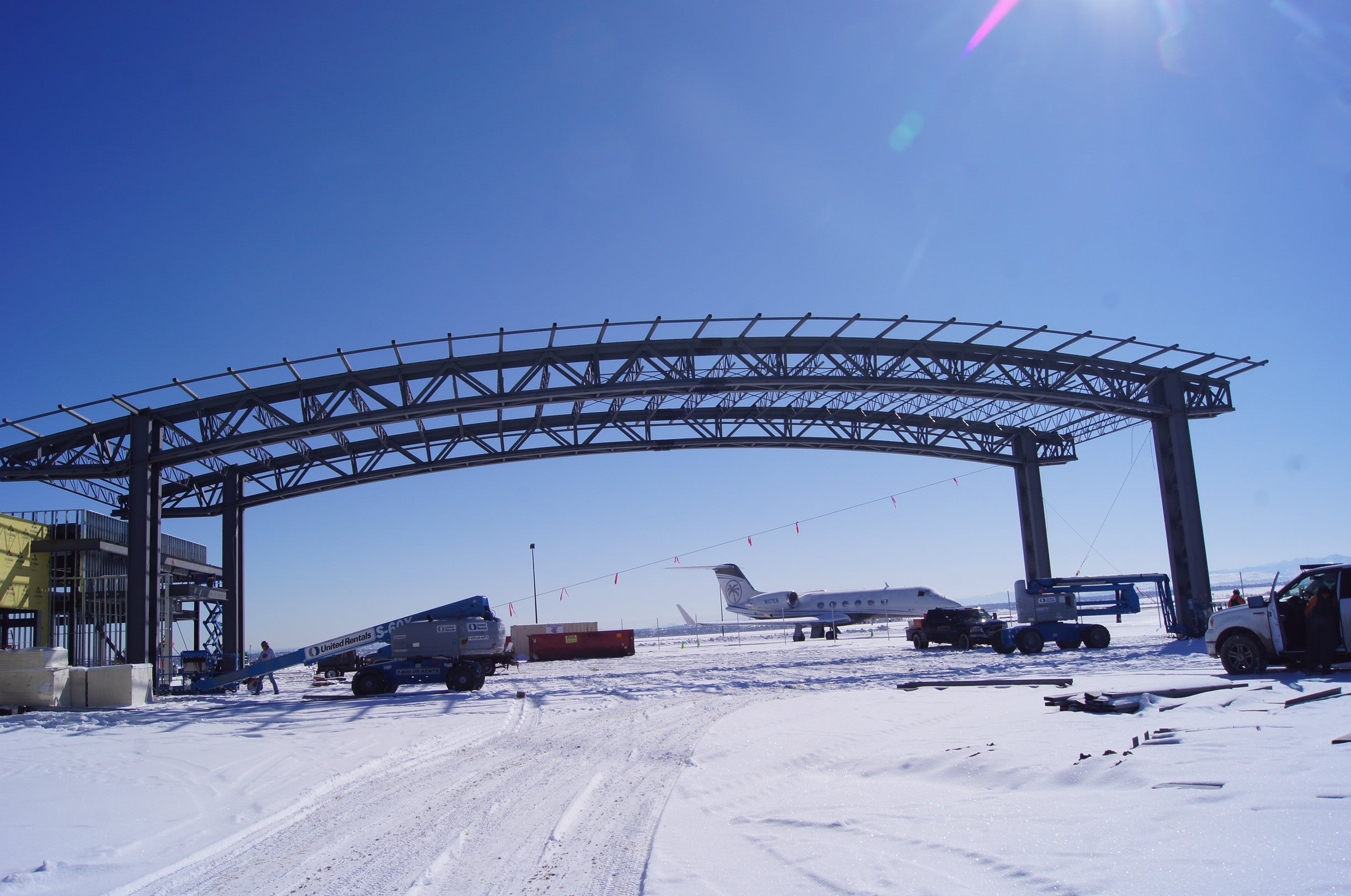
Rocky Mountain Metropolitan Airport drive-through canopy
Robbins Engineering*, founded in 2004 in Little Rock, Arkansas, designed this FBO(Fixed Base Operator) terminal and hangar for business aviation clients at a high-altitude airport with hurricane-force wind speeds.
The most prominent part of this unique project was 132-foot clear span arched trusses supporting the 40-foot-high canopy for aircraft.

Structure and Design
The canopy has been designed as a structure for planes to pull under for loading and unloading of passengers. But this type of structure represents a large surface and is stressed mainly by wind.
The design team investigated several options before deciding on arched trusses supported by built-up laced columns (Figure 1). Twin W24x192 columns, 4 feet apart with round bar X-bracing and W8 struts between them, form each of the 4 built-up columns. The arched trusses are 6 feet deep, using WT12x88 chords and double angle webs.
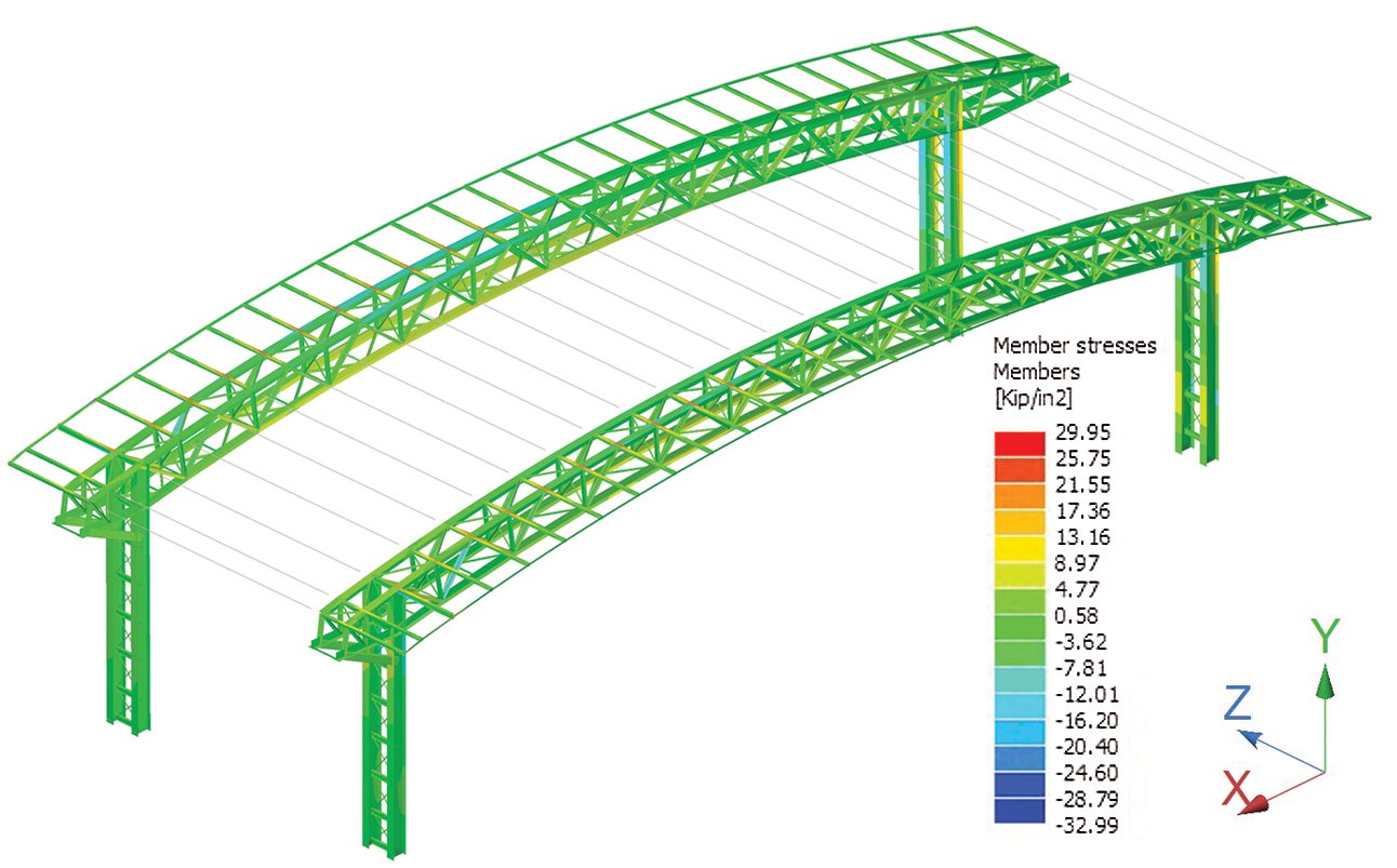
Figure 1. RAM Elements model of the high canopy for aircraft.
The 132-foot clear span has one field-bolted splice point near midspan. Each end of each truss is attached to the W24 column’s inside flange via bolted endplate moment connections (Figure 2). 10- and 20-foot cantilever truss sections are similarly attached to the outside flanges of the columns. Vertical X-bracing installed between each pair of trusses, as well as angle lacing in the planes of both top and bottom chords, form a space truss between each pair of built-up columns. This creates the moment frame in the long direction. Each pair of laced columns functions as cantilevered vertical trusses in the orthogonal axis. Concrete tie beams join the columns in the long direction to resist the arches’ thrust under gravity loads.
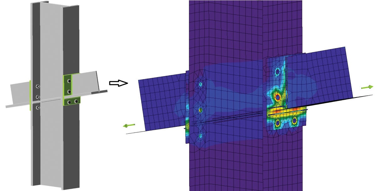
Figure 2. WT truss chord connected to the W24 column via endplates analyzed in Idea Statica
Connection. Cantilever to left of the column, backspan to the right.
The full article written by Jason McCool is accessible on the STRUCTURE Magazine website.
Using of the IDEA StatiCa application
Jason McCool, Project Engineer at Robbins Engineering, PLLC:
Other primary connection software we were used to using wasn´t able to check a beam splice joint with WT sections. Since I used WT12x88s for the chords of our arched canopy trusses, IDEA StatiCa application solved what would’ve otherwise been slow hand calcs or tedious spreadsheet creation. With its help, I quickly checked the splice joint with both endplates and lapped shear plates and iterated to the final optimized solution of lapped plates in double shear, even as I was still developing my global analysis model. Unfortunately, there isn’t a BIM link for the software we used for the global model, so I wasn’t able to take advantage of those features to transfer geometry and load information, but just being able to quickly explore nontypical options and adjust as needed was a huge help.

The endplate moment connection from the WT chords to the columns was another critical piece for us that other software couldn’t analyze. StatiCa allowed me to confidently eliminate unnecessary stiffeners and put more material where it was most useful. Welds could be sized knowing that nonuniform stress in the welds was directly accounted for rather than common assumptions of uniformity or the application of arbitrary increase factors that attempt to envelop any potential stress concentrations.

This example of an open web steel joist bearing on a column stiffener plate is another case where other software falls short. The typical assumption is that the stiffener plate is under only the tension or compression created by the flange forces in the beam transferring into the column as the structure racks. But Idea Statica allows for interaction effects such as compression in-plane and bending out-of-plane such as this case, or another common case of 4-way moment connections putting the strong-axis continuity plates into biaxial tension.

Below is a wind brace connection to a relatively small W-column on the FBO (Fixed Base Operator) building portion of the project. The brace load is wind and not seismic and is relatively small at this joint. But this is another connection configuration that is simply not addressed by our other connection design software. Rather than spending time doing tedious hand calcs or taking the “easy” way of quickly adding unnecessary stiffener plates or using a very thick endplate to err far on the conservative side, IDEA StatiCa Connection allows for a simple verification that the proposed connection is more than adequate.
The result is a very clean joint that is also easier to fabricate without the extra column stiffener plates. Later, another potential application of this connection arose on another part of the building on a slightly heavier column, but this time with 5 times the brace load. I had created a template from the first case and was able to quickly apply it to the new location and confirm that the same configuration worked, again without stiffeners. Plus, that template is now available for reuse on other projects.


Conclusion
REC benefitted in several ways by having IDEA StatiCa Connection. Although we use other connection design software, none of it is as open-ended. They are all formula-driven, and hence limited to whatever formulas have been derived in different codes and standards and then programmed by the software developer. But IDEA StatiCa really starts on a higher level than the others can ever reach by being able to build joints from basic components into complex configurations that the programmer wouldn’t have been able to anticipate beforehand. With CBFEM backing up the calculations, I’m not nearly as limited to what a programmer could envision ahead of time. Asymmetrical sections and bolt patterns, complex arrangements of stiffeners, determining the adequacy of as-built joints with “missing” components – these are all possible with Idea Statica where other programs have programmed assumptions like symmetrical arrangements, simple piecemeal analysis with no interaction between different portions, etc.
*Project Attribution Update
This project was originally completed while Jason McCool, PE, was employed at Robbins Engineering Consultants (REC), which ceased operations in 2024. The work is now attributed to the author’s current firm, Cool Country Engineering, with acknowledgment of REC as the original organization under which the project was performed.
