
Anchoring with no waiting: coordinate better between steel & concrete designers
To understand why this matters, let’s look at the reality of anchoring design today.
When baseplates are placed near edges or subjected to complex combinations of tension and shear, verifying the anchoring according to design standards such as EN 1992-4 becomes difficult. In many cases, reinforcement must be considered as part of the check. These verifications are usually carried out by a different engineer — typically the concrete specialist.
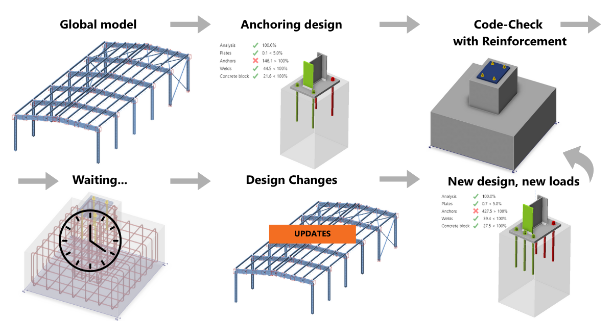
In practice, the steel designer defines the loads, anchor layout, baseplate thickness, and required stiffeners, while the concrete designer performs a separate verification of the concrete block and its reinforcement. As projects evolve, changes in geometry or in load distribution are inevitable. Each modification triggers another redesign cycle and another round of communication between teams — often complicated by inconsistent data exchange, unclear revisions, and mismatched time priorities of the designers.
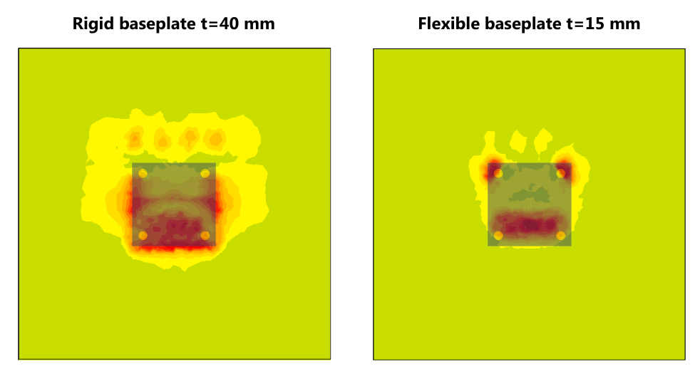
Moreover, the rigid or flexible behavior of the baseplate influences the stress in the concrete. And even if the steel designer wants to code-check the reinforcement independently, without relying on the concrete team, they often lack information about the additional forces the concrete element must resist, especially when anchoring into walls, beams, or columns.
To avoid frustrating delays and coordination loops, engineers often overdesign these details, applying conservative assumptions instead of capturing real behavior.
What if both sides could design and verify anchoring systems within the same environment — transparently, accurately, and without waiting for each other’s assumptions?
Anchoring from the steel engineer’s perspective
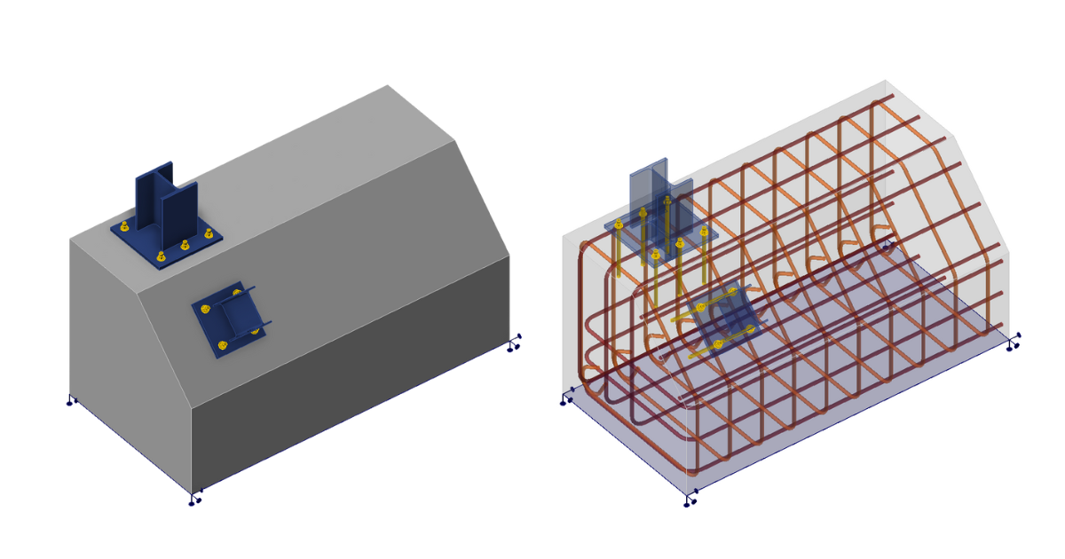
Traditionally, performing a check of supplementary reinforcement would require a deep understanding of the strut-and-tie method, especially for complex cases. It also requires an intuitive sense of stress flow within concrete. This is knowledge that only comes from years of experience, but with the Compatible Stress Field Method (3D CSFM) in IDEA StatiCa Detail, the design becomes intuitive and code-based. As a structural engineer primarily focused on steel design, I don’t need to be a specialist in reinforced concrete to consider supplementary reinforcement.
By following the reinforcement detailing rules, I can model a reinforced concrete block that includes supplementary bars, verify that:
- concrete class (C12/15, C20/25, etc.) is adequate for the design,
- concrete contains minimum reinforcement As,min,
- adequate anchorage, cover, and bond is provided, and
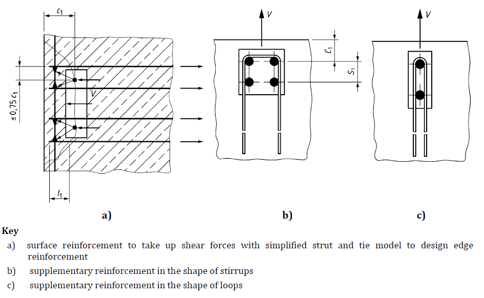
- the supplementary reinforcement bars are positioned within the recommended limits (for example, anchored outside the assumed failure body, positioned within a distance < 0.75·c₁ from the fastener, etc.).
Firstly, I code-check the steel part in IDEA StatiCa Connection, and then I export it to IDEA StatiCa Detail.
Once I introduce the reinforcement into the model, IDEA StatiCa performs the 3D CSFM calculation, showing exactly how the reinforcement contributes to capacity based on the stiffness of the baseplate and ensuring that the design meets all code requirements.
This means I can prepare a code-compliant reinforcement proposal. I am immediately able to see what reinforcement is required for the design to pass the checks and decide whether to adjust it or finalize it. Instead of waiting for feedback or relying on assumptions, I can instantly verify whether my anchoring design can carry the applied loads with supplementary reinforcement, or whether I, as the steel designer, need to refine my model further.
With this in mind, I am able to deliver a proposal to the concrete designer that already reflects realistic behavior and reinforcement requirements. The concrete designer then finalizes the reinforcement in the context of the other loads acting on the structure.
Anchoring from the concrete engineer’s perspective
As a concrete engineer, my task is to make sure the structure safely transfers the loads from the steel connection into the concrete without any concrete failures. To do that, firstly, I need to understand the stress distribution near the anchoring, check potential failures, and ensure that reinforcement is correctly placed and anchored to transfer the load of the steel part. This can be challenging, especially when I don’t know whether the baseplate behaves rigidly or flexibly, and anchored members are placed close to the edges, or multiple members are anchored to the concrete blocker. Small changes in geometry or load distribution can completely alter the behavior.
With IDEA StatiCa Detail (3D) and the 3D CSFM method, I can visualize how stresses spread through the concrete, identify critical areas, and verify the reinforcement. Instead of relying on simplified formulas or assumptions, I see exactly how reinforcement prevents concrete failures.
Depending on the workflow, I can receive the data directly from the steel designer, including internal forces exported from IDEA StatiCa Connection. When I receive the file, I can just open it, reinforce the concrete based on the internal forces, possibly add other loads if necessary, and code check it based on:
concrete strength in compression
\[\sigma_{c,eq} = \sigma_{c3} - \sigma_{c1} < f_{cd}\]
bond stress τb
\[\frac{τ_{b}}{f_{bd}}\le 1\]
where
\[f_{bd} = 2.25 \cdot η_1\cdot η_2\cdot f_{ctd}\]
and strength of the reinforcement
\(σ_{s,lim} = \frac{k \cdot f_{yk}}{γ_s}\qquad\qquad\textsf{\small{for bilinear diagram with inclined top branch}}\)
\(σ_{s,lim} = \frac{f_{yk}}{γ_s}\qquad\qquad\,\,\,\,\textsf{\small{for bilinear diagram with horizontal top branch}}\)
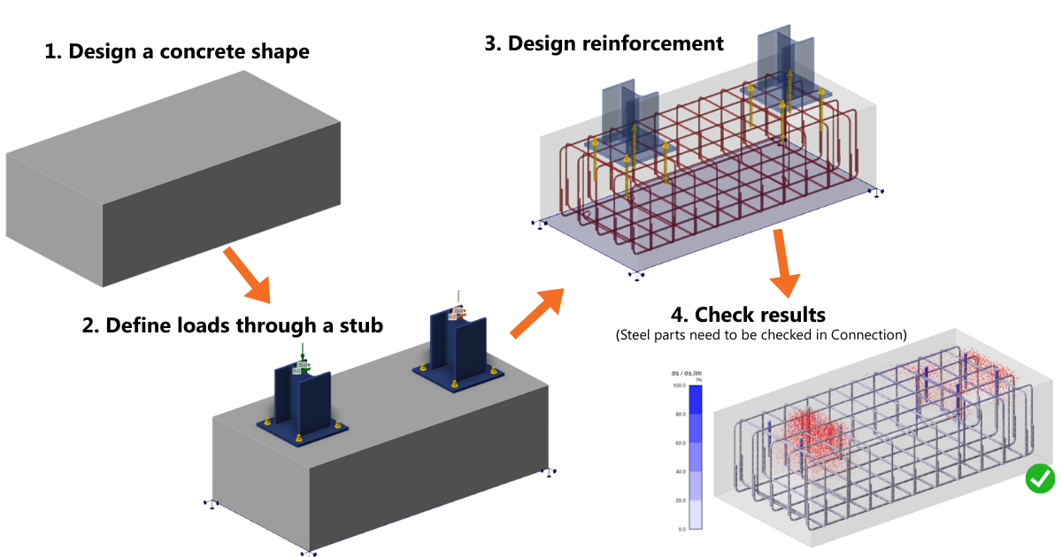
Or, if I only receive the resulting forces acting on the footing, I can start from scratch. I can model a stub representing a short portion of the steel column above the baseplate. The stub transfers the full set of internal forces (Fx, Fy, Fz, Mx, My, Mz) into the baseplate in a physically realistic way, ensuring that load redistribution through the plate, anchors, and concrete reflects real stiffness and behavior. This way, I can design the concrete reinforcement confidently and accurately from scratch.
What we bring in IDEA StatiCa 25.1 for both sides of the design
With version 25.1, we’re closing the gap between steel and concrete teams when it comes to anchoring design. The goal was simple — to let both sides model, verify, and communicate using the same data and the same understanding of how their designs actually behave. No waiting, no guesswork, just transparent collaboration built on realistic analysis.
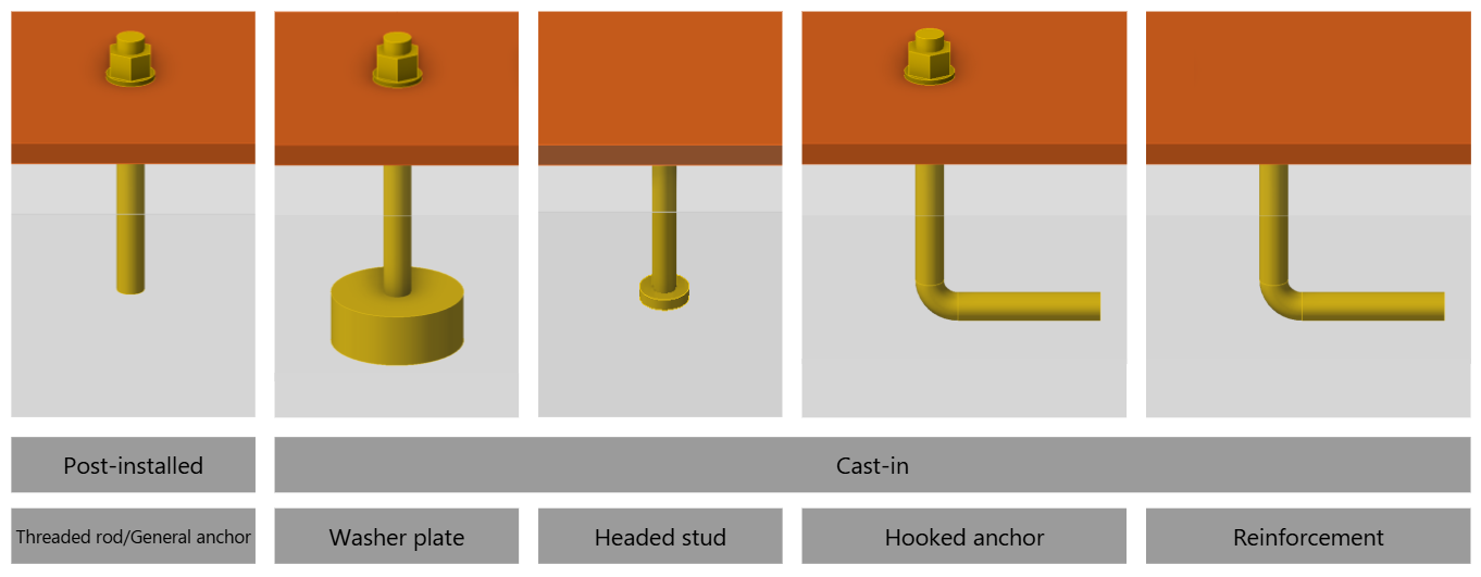
We also recognize that anchoring is much more than just supplementary reinforcement. Engineers often need to use specific anchoring types requested by various stakeholders (washer plates, hooked anchors, headed studs, and reinforcement), all available in IDEA StatiCa's applications.
Together, these enhancements provide a more complete and technically consistent workflow for both steel and concrete designers. Check out the complete steel-to-concrete anchoring use case here, and watch the webinar recording below to see how to handle complex mast anchorage with a real tower project from Denmark.
Take the latest version of IDEA StatiCa for a test drive today
IDEA StatiCa Detail – Structural design of concrete 3D discontinuities
