Verifica dei componenti del collegamento in acciaio (AISC)
CBFEM Il metodo CBFEM combina i vantaggi del Metodo degli Elementi Finiti generale e del metodo delle componenti standard. Le tensioni e le forze interne calcolate sull'accurato modello CBFEM vengono utilizzate nelle verifiche di tutti i componenti.
I singoli componenti sono verificati secondo l'American Institute of Steel Construction (AISC) 360-16.
Verifica normativa delle piastre in acciaio (AISC)
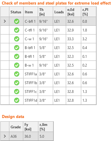
La tensione equivalente risultante (HMH, von Mises) e la deformazione plastica vengono calcolate sulle piastre. Quando viene raggiunta la tensione di snervamento (in LRFD moltiplicata per il fattore di resistenza del materiale ϕ = 0,9, in ASD divisa per il fattore di sicurezza del materiale Ω = 1,67, modificabili nel Code setup) nel diagramma bilineare del materiale, viene eseguita la verifica della deformazione plastica equivalente. Il valore limite del 5% è suggerito dall'Eurocode (EN1993-1-5 App. C, Par. C8, Nota 1). Questo valore può essere modificato nel Code setup, ma gli studi di verifica sono stati condotti per questo valore raccomandato.
L'elemento piastra è suddiviso in cinque strati e il comportamento elastico/plastico viene analizzato in ciascuno di essi. Il programma mostra il risultato peggiore tra tutti.
Il metodo CBFEM può fornire tensioni leggermente superiori alla tensione di snervamento. Il motivo è la leggera inclinazione del ramo plastico del diagramma tensione-deformazione, utilizzato nell'analisi per migliorare la stabilità del calcolo dell'interazione. Ciò non costituisce un problema per la progettazione pratica. La deformazione plastica equivalente viene superata a tensioni più elevate e il giunto non soddisfa comunque la verifica.
Verifica normativa delle saldature (AISC)
Le saldature a cordone d'angolo sono verificate secondo AISC 360 - Capitolo J2. La resistenza delle saldature a piena penetrazione (CJP) è assunta uguale a quella del metallo base e non viene verificata.
Saldature a cordone d'angolo
La resistenza di progetto, ϕRn, e la resistenza ammissibile, Rn/Ω, dei giunti saldati sono valutate nella verifica normativa delle saldature del collegamento.
ϕ = 0.75 (Load and Resistance Factor Design, LRFD, modificabile nelle impostazioni normative)
Ω = 2.00 (Allowable Strength Design, ASD, modificabile nelle impostazioni normative)
La resistenza disponibile dei giunti saldati è valutata secondo AISC 360-16 – J2.4
Rn = Fnw Awe
Fnw = 0.6 FEXX (1.0 + 0.5 sin1.5θ )
dove:
- Fnw – tensione nominale del materiale di saldatura
- Awe – area efficace della saldatura
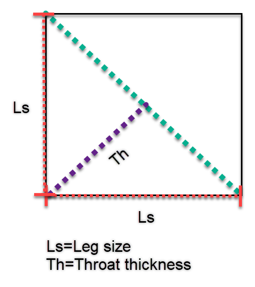
- Awe = Lc*Th
- FEXX – numero di classificazione dell'elettrodo, ovvero resistenza a trazione minima specificata
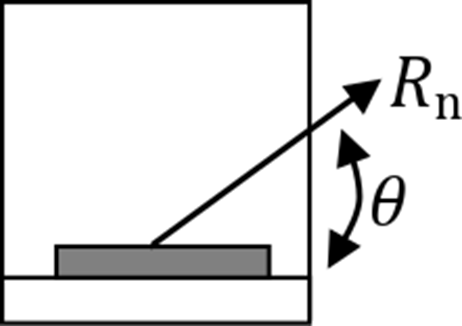
- θ – angolo calcolato tra l'asse longitudinale della saldatura e la direzione della forza risultante agente nell'elemento finito più sollecitato della saldatura.
Si noti che l'incremento di resistenza direzionale non viene applicato alle saldature in cui è collegato il bordo di un profilo cavo rettangolare (AISC 360-16:2022 – J2.4.(2).
La resistenza del metallo base viene valutata se l'opzione è selezionata nelle impostazioni normative (Capacità del metallo base alla faccia di fusione).
Rn = FnBM ABM – AISC 360-16 – J2.4 (J2-2)
dove:
- FnBM = 0.6 Fu – resistenza nominale del metallo base – AISC 360-16 – J4.2 (J4-4)
- \( A_{BM}=A_{we}\sqrt{2} \) – area della sezione trasversale del metallo base
- Fu – resistenza a trazione minima specificata
Tutti i valori necessari per la verifica normativa sono riportati nelle tabelle.
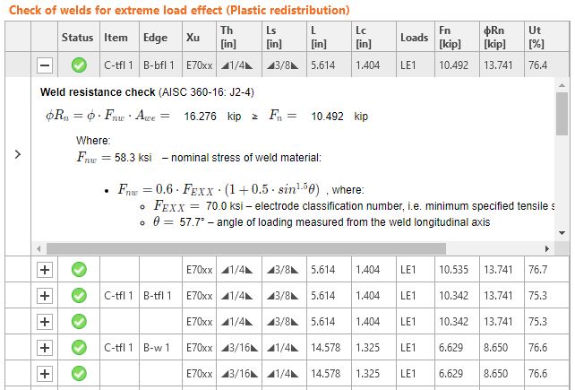
dove:
- Xu – elettrodo di saldatura utilizzato
- Th – spessore di gola della saldatura (calcolato da Ls)
- Ls – dimensione del cateto della saldatura (input utente)
- \(L\) – lunghezza totale della saldatura
- \(L_c\) – lunghezza dell'elemento critico della saldatura
- Loads – effetto del carico critico per la saldatura analizzata
- \(F_n\) – forza nell'elemento critico della saldatura
- \(\phi\)Rn – resistenza della saldatura
- Ut – sfruttamento dell'elemento critico della saldatura
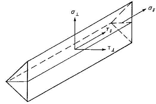
La forza, \(F_n\), e l'angolo della saldatura, \(\theta\), sono derivati dalle tensioni \( \sigma_{\perp}, ,\ \tau_{\perp}, \, \tau_{\parallel}\), dalla lunghezza e dall'area efficace dell'elemento finito della saldatura. Queste tensioni sono l'output di base del solutore agli elementi finiti.
I diagrammi della saldatura mostrano la tensione secondo le seguenti formule:
Se il metallo base è disattivato (viene utilizzato un elettrodo abbinato):
\[ \sigma = \frac{\sqrt{ \sigma_{\perp}^2 + \tau_{\perp}^2 + \tau_{\parallel}^2 }}{1+0.5 \sin^{1.5}{\theta}} \]
Se il metallo base è attivato (non viene utilizzato un elettrodo abbinato):
\[ \sigma = \max \left \{ \frac{\sqrt{ \sigma_{\perp}^2 + \tau_{\perp}^2 + \tau_{\parallel}^2 }}{1+0.5 \sin^{1.5}{\theta}}, \, \frac{\sqrt{ \sigma_{\perp}^2 + \tau_{\perp}^2 + \tau_{\parallel}^2 }}{\sqrt{2} F_u / F_{EXX}} \right \} \]
Nota per l'utente: In IDEA StatiCa, quando la dimensione del cateto della saldatura è impostata su 0, viene utilizzato il seguente valore:
- Per saldatura a cordone d'angolo su un solo lato, lo spessore di gola è uguale allo spessore del piatto collegato più sottile.
- Per saldatura a cordone d'angolo su entrambi i lati, lo spessore di gola è uguale alla metà dello spessore del piatto collegato più sottile.
Saldature a piena penetrazione (CJP)
La Tabella J2.5 della specifica AISC individua quattro condizioni di carico che possono essere associate alle saldature a piena penetrazione e mostra che la resistenza del giunto è controllata dal metallo base oppure che i carichi non devono essere considerati nella progettazione delle saldature che collegano le parti. Di conseguenza, quando le saldature a piena penetrazione (CJP) sono eseguite con metallo d'apporto di resistenza abbinata, la resistenza del collegamento è governata o controllata dal metallo base e non sono richieste verifiche sulla resistenza della saldatura.
Saldature a parziale penetrazione (PJP)
La resistenza di progetto, ϕRn, e la resistenza ammissibile, Rn/Ω, della saldatura a parziale penetrazione (PJP) sono determinate secondo AISC 360-22 – Tabella J2.5). Si assume il caso più conservativo – tipo di carico a taglio.
ϕ = 0.75 (Load and Resistance Factor Design, LRFD, modificabile nelle impostazioni normative)
Ω = 2.00 (Allowable Strength Design, ASD, modificabile nelle impostazioni normative)
La resistenza disponibile dei giunti saldati è valutata secondo AISC 360-16 – J2.4
Rn = Fnw Awe
dove:
- Fnw = 0.6 FEXX – tensione nominale del materiale di saldatura
- Awe – area efficace della saldatura
- Awe = Lc E
- FEXX – numero di classificazione dell'elettrodo, ovvero resistenza a trazione minima specificata
- Lc – lunghezza dell'elemento critico della saldatura
- E – gola efficace della saldatura PJP
La resistenza del metallo base viene valutata se l'opzione è selezionata nelle impostazioni normative (Capacità del metallo base alla faccia di fusione).
Rn = FnBM ABM – AISC 360-22 – J2.4 (J4)
dove:
- FnBM = 0.6 Fu – resistenza nominale del metallo base – AISC 360-22 – J4.2 (J4-4)
- \( A_{BM}=A_{we} \) – area della sezione trasversale del metallo base assunta uguale all'area efficace della saldatura
- Fu – resistenza a trazione minima specificata del metallo base
Verifica normativa di bulloni e bulloni precaricati (AISC)
Le forze nei bulloni sono determinate tramite analisi agli elementi finiti. Le forze di trazione includono le forze di leva. Le resistenze dei bulloni sono verificate secondo AISC 360 - Capitolo J3.
Bulloni
Resistenza a trazione e a taglio dei bulloni
La resistenza a trazione o a taglio di progetto, ϕRn, e la resistenza a trazione o a taglio ammissibile, Rn/Ω, di un bullone serrato a contatto sono determinate secondo gli stati limite di rottura a trazione e rottura a taglio come segue:
Rn = FnAb
ϕ = 0.75 (LRFD, modificabile in Impostazioni normativa)
Ω = 2.00 (ASD, modificabile in Impostazioni normativa)
dove:
Ab – area nominale del corpo non filettato del bullone o della parte filettata
Fn – tensione nominale a trazione, Fnt, o tensione nominale a taglio, Fnv, dalla Tabella J3.2
La resistenza a trazione richiesta include qualsiasi trazione derivante dall'azione di leva prodotta dalla deformazione delle parti collegate.
Trazione e taglio combinati in collegamento di tipo a rifollamento
La resistenza a trazione disponibile di un bullone soggetto a trazione e taglio combinati è determinata secondo gli stati limite di rottura a trazione e a taglio come segue:
Rn = F'nt Ab (AISC 360-16 J3-2)
ϕ = 0.75 (LRFD, modificabile in Impostazioni normativa)
Ω = 2.00 (ASD, modificabile in Impostazioni normativa)
\( F'_{nt}=1.3 F_{nt} - \frac{f_{rv} F_{nt}}{\phi F_{nv}} \) (AISC 360-16 J3-3a LRFD)
\( F'_{nt}=1.3 F_{nt} - \frac{f_{rv} \Omega F_{nt}}{F_{nv}} \) (AISC 360-16 J3-3b ASD)
dove:
- F'nt – tensione nominale a trazione modificata per includere gli effetti della tensione di taglio
- Fnt – tensione nominale a trazione dalla Tabella J3.2 di AISC 360-16
- Fnv – tensione nominale a taglio dalla Tabella J3.2 di AISC 360-16
- frv – tensione di taglio richiesta utilizzando le combinazioni di carico LRFD o ASD. La tensione di taglio disponibile dell'elemento di fissaggio deve essere uguale o superiore alla tensione di taglio richiesta, frv
Resistenza al rifollamento nei fori dei bulloni
Le resistenze al rifollamento disponibili, ϕRn e Rn/Ω, nei fori dei bulloni sono determinate per lo stato limite di rifollamento come segue:
ϕ = 0.75 (LRFD, modificabile in Impostazioni normativa)
Ω = 2.00 (ASD, modificabile in Impostazioni normativa)
La resistenza nominale al rifollamento del materiale collegato, Rn, è determinata come segue:
Per un bullone in un collegamento con fori standard:
Rn = 1.2 lc t Fu ≤ 2.4 d t Fu (AISC 360-16 J3-6a, J3-6a, c)
Per un bullone in un collegamento con fori assolettati:
Rn = 1.0 lc t Fu ≤ 2.0 d t Fu (AISC 360-16 J3-6a, J3-6e, f)
dove:
- Fu – resistenza minima specificata a trazione del materiale collegato
- d – diametro nominale del bullone
- lc – distanza netta, nella direzione della forza, tra il bordo del foro e il bordo del foro adiacente o il bordo del materiale
- t – spessore del materiale collegato
Bulloni precaricati
La resistenza allo scorrimento di progetto del bullone precaricato di classe A325 o A490 con l'effetto della forza di trazione Ft
Forza di precarico da utilizzare AISC 360-10 tab. J3.1.
Tb = 0.7 fub As
Resistenza allo scorrimento di progetto per bullone AISC 360-10 par. J3.8
Rn = kSC μ Du hf Tb ns
Sfruttamento a taglio [%]:
Uts = V / ϕRn (LRFD)
Uts = Ω V / Rn (ASD)
dove:
- As – area della sezione resistente a trazione del bullone
- fub – resistenza ultima a trazione
- \( k_{SC}=1-\frac{F_t}{D_u T_b n_b} \) – fattore per trazione e taglio combinati (LRFD) (J3-5a)
- \( k_{SC}=1-\frac{1.5 F_t}{D_u T_b n_b} \) – fattore per trazione e taglio combinati (ASD) (J3-5b)
- μ – coefficiente medio di attrito modificabile in Impostazioni normativa
- Du = 1.13 – moltiplicatore che riflette il rapporto tra la pretensione media installata del bullone e la pretensione minima specificata del bullone
- hf = 1.0 – fattore per i riempitivi
- ns – numero di superfici di attrito; la verifica è calcolata separatamente per ciascuna superficie di attrito
- V – forza di taglio agente sul bullone
- ϕ = 1.0 – fattore di resistenza per fori di dimensione standard (LRFD) modificabile in Impostazioni normativa
- ϕ = 0.7 – fattore di resistenza per fori assolettati (LRFD)
- Ω = 1.5 – fattore di resistenza per fori di dimensione standard (ASD) modificabile in Impostazioni normativa
- Ω = 2.14 – fattore di resistenza per fori assolettati (ASD)
Verifica normativa dei blocchi in calcestruzzo (AISC)
Il calcestruzzo sotto la piastra di base è simulato dal sottosuolo di Winkler con rigidezza uniforme, che fornisce le tensioni di contatto. La tensione media nell'area caricata in contatto con la piastra di base è utilizzata per la verifica a compressione.
Calcestruzzo in compressione
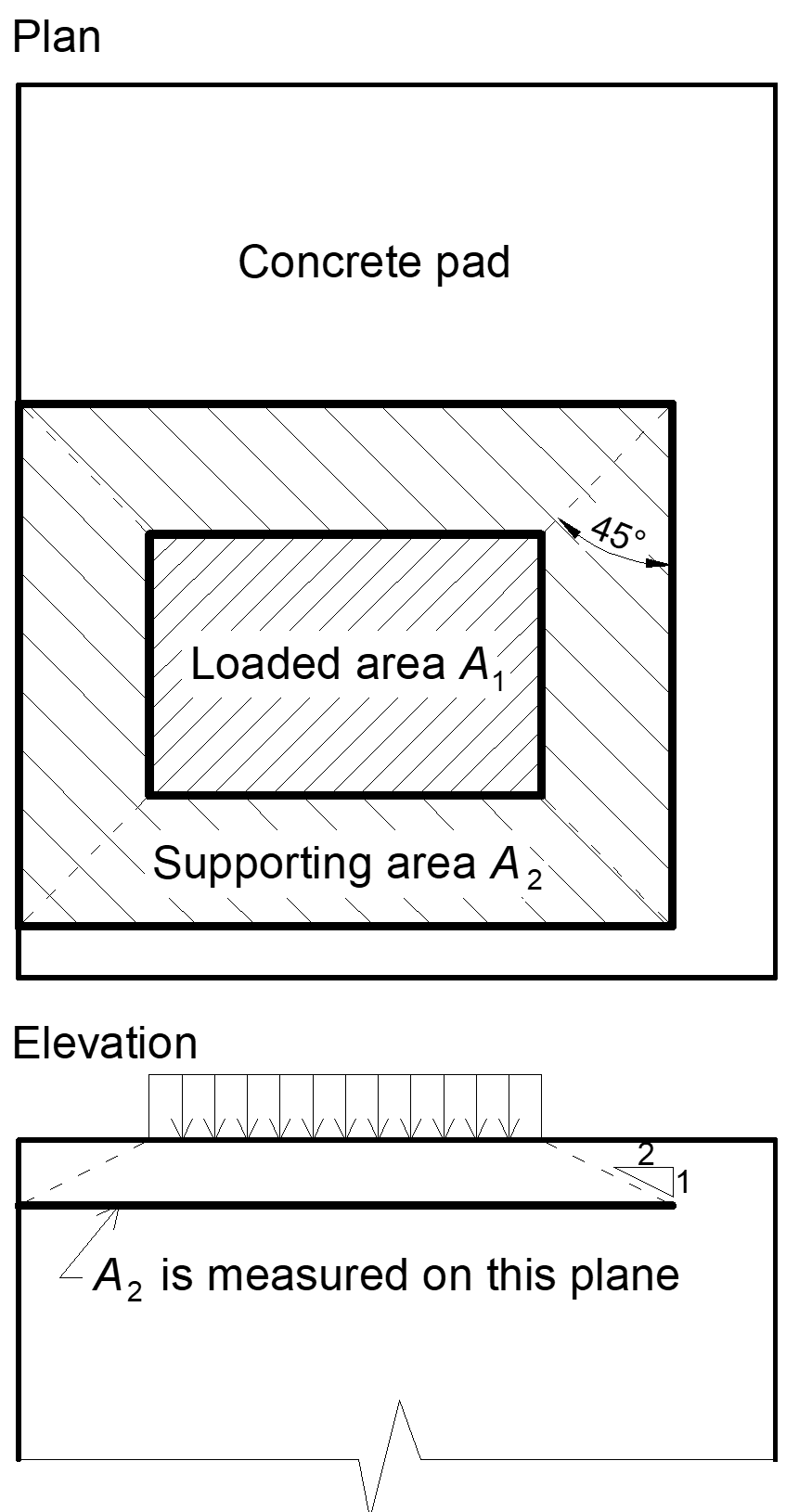
Progettazione del calcestruzzo La resistenza di progetto a cuscinetto in compressione è verificata secondo AISC 360-16, Sezione J8. Quando la superficie di appoggio del calcestruzzo è maggiore della piastra di base, la resistenza di progetto a cuscinetto è definita come
\[ f_{p(max)}=0.85 f_c \sqrt{\frac{A_2}{A_1}} \le 1.7 f'_c \]
dove:
- f'c – resistenza a compressione del calcestruzzo
- A1 – area della piastra di base in contatto con la superficie in calcestruzzo (area della superficie superiore del tronco di piramide)
- A2 – superficie di appoggio del calcestruzzo (area inferiore geometricamente simile del tronco di piramide con pendenze di 1 verticale su 2 orizzontale)
La verifica del calcestruzzo all'appoggio è la seguente
σ ≤ ϕc fp(max) per LRFD
σ ≤ fp(max) / Ωc per ASD
dove:
- σ – tensione media di compressione sotto la piastra di base
- ϕc = 0.65 – fattore di resistenza per il calcestruzzo
- Ωc = 2.31 – fattore di sicurezza per il calcestruzzo
Trasferimento delle forze di taglio
I carichi di taglio possono essere trasferiti tramite una delle seguenti opzioni:
- Chiavetta a taglio,
- Attrito,
- Bulloni di ancoraggio.
Chiavetta a taglio
È disponibile solo LRFD. Il carico di taglio è trasferito tramite la chiavetta a taglio. Sono necessarie le verifiche del calcestruzzo all'appoggio e, a meno che non sia fornita armatura per sviluppare la resistenza richiesta, le verifiche di rottura del calcestruzzo per estrazione.
La capacità portante all'appoggio della chiavetta a taglio contro il calcestruzzo è determinata secondo ACI 349-01 – B.4.5 e ACI 349-01 RB11 come:
ϕPbr = ϕ 1.3 f'c A1 + ϕ Kc (Ny – Pa)
dove:
- ϕ = 0.7 – fattore di riduzione della resistenza per appoggio sul calcestruzzo secondo ACI 349
- f'c – resistenza a compressione del calcestruzzo
- A1 – area proiettata della chiavetta a taglio annegata nella direzione della forza, esclusa la parte del piolo a contatto con la malta sopra l'elemento in calcestruzzo
- Kc = 1.6 – coefficiente di confinamento
- Ny = n Ase Fy – resistenza allo snervamento degli ancoraggi tesi
- Pa – carico assiale esterno
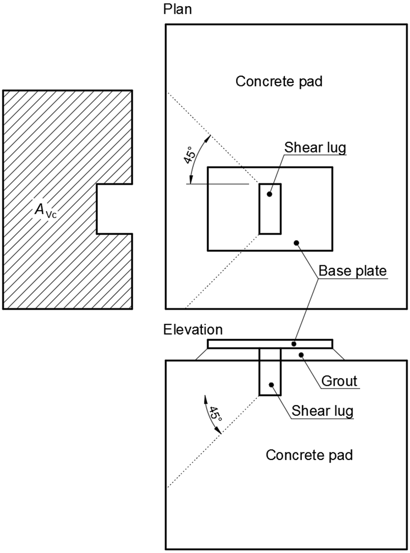
La resistenza alla rottura del calcestruzzo della chiavetta a taglio secondo ACI 349 – B11 è:
\[ \phi V_{cb} = A_{Vc} 4 \phi \sqrt{f'_c} \]
dove:
- ϕ = 0.85 – fattore di riduzione della resistenza a taglio secondo ACI 349
- AVc – area di tensione efficace definita proiettando un piano a 45° dai bordi di appoggio della chiavetta a taglio fino alla superficie libera nella direzione del carico di taglio. L'area di appoggio della chiavetta a taglio è esclusa dall'area proiettata
Se la resistenza alla rottura del calcestruzzo è disabilitata nelle impostazioni normative, all'utente viene fornita la forza che deve essere trasferita tramite il calcestruzzo armato.
Attrito
Il carico di taglio è trasferito tramite attrito. La resistenza a taglio è determinata come:
ϕc Vr = ϕc μ C (LRFD)
Vr / Ωc =μ C / Ωc (ASD)
dove:
- ϕc = 0.65 – fattore di resistenza (LRFD)
- Ωc = 2.31 – fattore di sicurezza (ASD)
- μ = 0.4 – coefficiente di attrito tra la piastra di base e il calcestruzzo (valore raccomandato 0.4 nella Guida di Progettazione AISC 7 – 9.2 e ACI 349 – B.6.1.4, modificabile nelle impostazioni normative)
- C – forza di compressione
Bulloni di ancoraggio
Se il carico di taglio è trasferito esclusivamente tramite bulloni di ancoraggio, la forza di taglio agente su ciascun ancoraggio è determinata tramite il Metodo degli Elementi Finiti e i bulloni di ancoraggio sono verificati secondo ACI 318-14 come descritto nei capitoli seguenti.
Verifica normativa degli ancoraggi (AISC)
Le forze negli ancoraggi, incluse le forze di leva, sono determinate tramite analisi agli elementi finiti, ma le resistenze sono verificate utilizzando le disposizioni normative di ACI 318-14, ACI 318-19 o ACI 318-25, a seconda dell'edizione della norma selezionata.
È disponibile solo LFRD. È possibile selezionare i seguenti tipi di sistemi di ancoraggio:
- Gettato in opera
- Con piastra rondella
- Ancorante con gancio
- Piolo con testa
- Armatura
- Ancoraggi post-installati
- Barra filettata
I tirafondi sono progettati secondo AISC 360-10/16/22 – J9 e ACI 318-14/19/25 – Capitolo 17. Le seguenti resistenze dei bulloni di ancoraggio sono valutate in funzione del sistema di ancoraggio selezionato:
- Resistenza dell'acciaio dell'ancoraggio a trazione ϕNsa,
- Resistenza a rottura del calcestruzzo per cono a trazione ϕNcbg,
- Resistenza a sfilamento del calcestruzzo ϕNp,
- Resistenza a esplosione laterale del calcestruzzo ϕNsb,
- Resistenza dell'acciaio dell'ancoraggio a taglio ϕVsa,
- Resistenza a rottura del calcestruzzo per cono a taglio ϕVcbg,
- Resistenza a pryout del calcestruzzo dell'ancoraggio a taglio ϕVcp.
L'utente deve selezionare la condizione del calcestruzzo (fessurato o non fessurato – senza fessure in condizioni di esercizio).
Le seguenti verifiche degli ancoraggi caricati a trazione non sono fornite e devono essere verificate utilizzando le informazioni nella relativa Specifica Tecnica del Prodotto (basata sul frattile del 5% dei test eseguiti e valutati secondo ACI 355.2):
- Rottura per sfilamento dell'elemento di fissaggio (per ancoraggi meccanici post-installati) – ACI 318-14 – 17.4.3 o ACI 318-19/25 – 17.6.3,
- Resistenza di aderenza dell'ancorante adesivo (per ancoraggi post-installati incollati) – ACI 318-14 – 17.4.5 o ACI 318-19/25 – 17.6.5,
- La rottura per fessurazione del calcestruzzo durante l'installazione deve essere valutata secondo i requisiti di ACI 355.2.
La rottura per esplosione del calcestruzzo è prevista solo per gli ancoraggi con piastre rondella.
Resistenza dell'acciaio dell'ancoraggio a trazione
Tipi di ancoraggio: Con piastra rondella, Ancorante con gancio, Piolo con testa, Barra filettata:
La resistenza dell'acciaio dell'ancoraggio a trazione è determinata secondo ACI 318-14 – 17.4.1 o ACI 318-19/25 – 17.6.1 come
ϕNsa = ϕ Ase,N futa
dove:
- ϕ = 0.7 – fattore di riduzione della resistenza per ancoraggi a trazione secondo ACI 318-14 – 17.3.3, il fattore è modificabile nelle impostazioni della norma
- Ase,N – area della sezione resistente a trazione
- futa – resistenza a trazione specificata dell'acciaio dell'ancoraggio e non deve essere maggiore di 1.9 fya e 125 ksi
Tipo di ancoraggio: Armatura:
La resistenza dell'acciaio dell'ancoraggio a trazione è determinata secondo ACI 318-14/19/25 – 20.2.2 come
ϕNsa = ϕ As fy
dove:
- ϕ = 0.7 – fattore di riduzione della resistenza per ancoraggi a trazione secondo ACI 318-14 – 17.3.3, il fattore è modificabile nelle impostazioni della norma
- As – area della sezione resistente a trazione
- fy – limite di snervamento specificato dell'acciaio dell'ancoraggio
Resistenza a rottura del calcestruzzo per cono
Tutti i tipi di ancoraggio:
La resistenza a rottura del calcestruzzo per cono è progettata secondo il metodo Concrete Capacity Design (CCD) in ACI 318-14/19/25 – Capitolo 17. Nel metodo CCD, il cono di calcestruzzo è considerato formato con un angolo di circa 34° (pendenza 1 verticale a 1.5 orizzontale). Per semplicità, il cono è considerato quadrato anziché circolare in pianta. La tensione di rottura del calcestruzzo nel metodo CCD è considerata decrescente all'aumentare delle dimensioni della superficie di rottura. Di conseguenza, l'incremento di resistenza della rottura nel metodo CCD è proporzionale alla profondità di infissione elevata alla potenza di 1.5. Gli ancoraggi i cui coni di calcestruzzo si sovrappongono formano un gruppo di ancoraggi che genera un cono di calcestruzzo comune. Si noti che non esiste una soluzione ASD equivalente per il progetto della capacità del calcestruzzo.
\[ \phi N_{cbg} = \phi \frac{A_{Nc}}{A_{Nco}} \psi_{ec,N} \psi_{ed,N} \psi_{c,N} \psi_{cp,N} N_b \]
dove:
- ϕ = 0.7 – fattore di riduzione della resistenza per ancoraggi a trazione secondo ACI 318-14 – 17.3.3, il fattore è modificabile nelle impostazioni della norma
- ANc – area effettiva del cono di rottura del calcestruzzo per un gruppo di ancoraggi che formano un cono di calcestruzzo comune
- ANco = 9 hef2 – area del cono di rottura del calcestruzzo per un singolo ancoraggio non influenzato dai bordi
- \( \psi_{ec,N} = \frac{1}{1+\frac{2 e'_N}{3 h_{ef}}} \) – fattore di modifica per gruppi di ancoraggi caricati eccentricamente a trazione; nel caso in cui esista un carico eccentrico rispetto a due assi, il fattore di modifica Ψec,N è calcolato per ciascun asse singolarmente e il prodotto di questi fattori viene utilizzato
- \( \psi_{ed,N} = \min \left ( 0.7 + \frac{0.3 c_{a,min}}{1.5 h_{ef}}, 1 \right ) \) – fattore di modifica per la distanza dal bordo
- ca,min – distanza minima dall'ancoraggio al bordo
- Ψc,N – fattore di modifica per le condizioni del calcestruzzo; Ψc,N =1 per calcestruzzo fessurato, Ψc,N =1.25 per calcestruzzo non fessurato
- Ψcp,N = min (ca,min / cac,1) – fattore di modifica per la fessurazione per ancoraggi post-installati progettati per calcestruzzo non fessurato senza armatura supplementare per il controllo della fessurazione; Ψcp,N = 1 per tutti gli altri casi
- \( N_b = k_c \lambda_a \sqrt{f'_c} h_{ef}^{1.5} \) – resistenza di base a rottura del calcestruzzo per cono di un singolo ancoraggio a trazione in calcestruzzo fessurato; per ancoraggi gettati in opera e 11 in. ≤ hef ≤ 25 in. \( N_b = 16 \lambda_a \sqrt{f'_c} h_{ef}^{5/3} \)
- kc = 24 per ancoraggi gettati in opera
- hef – profondità di infissione; secondo il Capitolo 17.4.2.3 di ACI 318-14, la profondità di infissione effettiva hef è ridotta a \( h_{ef} = \max \left ( \frac{c_{a,max}}{1.5}, \frac{s}{3} \right ) \) se gli ancoraggi si trovano a meno di 1.5 hef da tre o più bordi
- s – interasse tra gli ancoraggi
- ca,max – distanza massima da un ancoraggio a uno dei tre bordi vicini
- λa = 1 – fattore di modifica per calcestruzzo alleggerito
- f'c – resistenza a compressione del calcestruzzo [psi]
Secondo ACI 318-14 – 17.4.2.8, nel caso di ancoraggi con testa, l'area della superficie proiettata ANc è determinata dal perimetro effettivo della piastra rondella, che è il valore minore tra da + 2 twp e dwp, dove:
- da – diametro dell'ancoraggio
- dwp – diametro o dimensione del lato della piastra rondella
- twp – spessore della piastra rondella
Secondo ACI 318-14
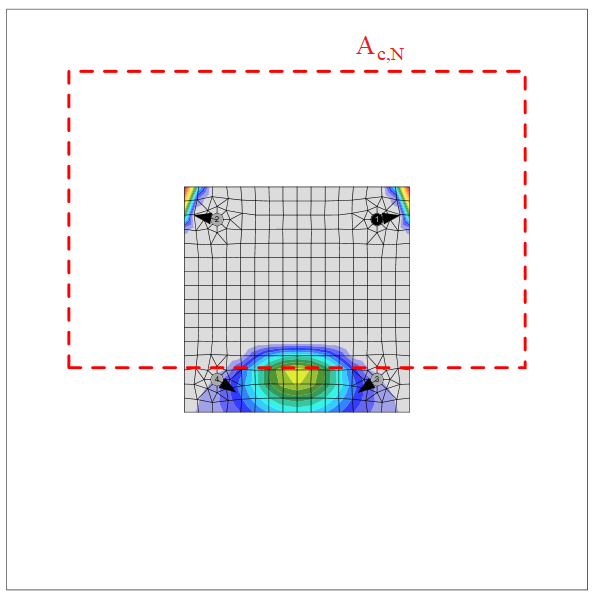
Il gruppo di ancoraggi è verificato rispetto alla somma delle forze di trazione negli ancoraggi caricati a trazione che formano un cono di calcestruzzo comune.
L'area del cono di rottura del calcestruzzo per il gruppo di ancoraggi caricati a trazione che formano un cono di calcestruzzo comune, Ac,N, è mostrata dalla linea tratteggiata rossa.
Secondo ACI 318-14 – 17.4.2.9, qualora l'armatura di ancoraggio sia sviluppata in conformità con ACI 318-14 – 25 su entrambi i lati della superficie di rottura, si presume che l'armatura di ancoraggio trasferisca le forze di trazione e la resistenza a rottura del calcestruzzo per cono non viene valutata.
Resistenza a sfilamento del calcestruzzo
Bulloni di ancoraggio con piastra rondella (bulloni con testa):
La resistenza a sfilamento del calcestruzzo di un bullone di ancoraggio con testa è definita in ACI 318-14 – 17.4.3 come
ϕNpn = ϕΨc,P Np
dove:
- ϕ = 0.7 – fattore di riduzione della resistenza per ancoraggi a trazione secondo ACI 318-14 – 17.3.3, modificabile nelle impostazioni della norma
- Ψc,P – fattore di modifica per le condizioni del calcestruzzo; Ψc,P = 1.0 per calcestruzzo fessurato, Ψc,P = 1.4 per calcestruzzo non fessurato
- NP = 8 Abrg f'c per ancoraggio con testa
- Abrg – area di appoggio della testa del piolo o del bullone di ancoraggio
- f'c – resistenza a compressione del calcestruzzo
Bulloni di ancoraggio con gancio (bulloni a J o a L):
La resistenza a sfilamento del calcestruzzo di un bullone di ancoraggio con gancio è definita in ACI 318-14 – 17.4.3 come
ϕNpn = ϕΨc,P Np
dove:
- ϕ = 0.7 – fattore di riduzione della resistenza per ancoraggi a trazione secondo ACI 318-14 – 17.3.3, modificabile nelle impostazioni della norma
- Ψc,P – fattore di modifica per le condizioni del calcestruzzo; Ψc,P = 1.0 per calcestruzzo fessurato, Ψc,P = 1.4 per calcestruzzo non fessurato
- NP = 0.9 f'c eh da per bullone di ancoraggio con gancio
- f'c – resistenza a compressione del calcestruzzo
- eh – distanza dalla superficie interna del fusto di un bullone a J o a L alla punta esterna del bullone a J o a L
- da – diametro del bullone di ancoraggio
La resistenza a sfilamento del calcestruzzo per tipi di ancoraggi diversi da quelli con testa o con gancio non è valutata nel software e deve essere specificata dal produttore.
Resistenza a esplosione laterale del calcestruzzo
La resistenza a esplosione laterale del calcestruzzo di un ancoraggio con testa a trazione è definita in ACI 318-14 – 17.4.4 come
\[ \phi N_{sb} = \phi 160 c_{a1} \sqrt{A_{brg}} \sqrt{f'_c} \]
La resistenza a esplosione laterale del calcestruzzo è moltiplicata per uno dei seguenti fattori di riduzione:
- \( \frac{1+\frac{c_{a2}}{c_{a1}}}{4} \le 1 \)
- \( \frac{1+\frac{s}{6 c_{a1}}}{2} \le 1 \)
dove:
- ϕ = 0.7 – fattore di riduzione della resistenza per ancoraggi a trazione secondo ACI 318-14 – 17.3.3, modificabile nelle impostazioni della norma
- ca1 – distanza minore dalla linea d'asse di un ancoraggio al bordo
- ca2 – distanza maggiore, perpendicolare a ca1, dalla linea d'asse di un ancoraggio al bordo
- Abrg – area di appoggio della testa del piolo o del bullone di ancoraggio
- f'c – resistenza a compressione del calcestruzzo
- s – interasse tra due ancoraggi adiacenti vicino a un bordo
Resistenza dell'acciaio a taglio
La resistenza dell'acciaio a taglio è determinata secondo ACI 318-14 – 17.5.1 come
ϕVsa = ϕ 0.6 Ase,V futa
dove:
- ϕ = 0.65 – fattore di riduzione della resistenza per ancoraggi a trazione secondo ACI 318-14 – 17.3.3, modificabile nelle impostazioni della norma
- Ase,V – area della sezione resistente a trazione
- futa – resistenza a trazione specificata dell'acciaio dell'ancoraggio e non deve essere maggiore di 1.9 fya e 125 ksi
Se è selezionato il giunto di malta, la resistenza a taglio dell'acciaio Vsa è moltiplicata per 0.8 (ACI 318-14 – 17.5.1.3).
Il taglio sul braccio di leva, presente nel caso di piastra di base con fori sovradimensionati e rondelle o piastre aggiunte sulla parte superiore della piastra di base per trasmettere la forza di taglio, non è considerato.
Resistenza a rottura del calcestruzzo per cono dell'ancoraggio a taglio
La resistenza a rottura del calcestruzzo per cono di un ancoraggio o di un gruppo di ancoraggi a taglio è progettata secondo ACI 318-14 – 17.5.2.
\[ \phi V_{cbg} = \phi \frac{A_V}{A_{Vo}} \psi_{ec,V} \psi_{ed,V} \psi_{c,V} \psi_{h,V} \psi_{\alpha,V} V_b \]
dove:
- ϕ = 0.65 – fattore di riduzione della resistenza per ancoraggi a taglio secondo ACI 318-14 – 17.3.3, modificabile nelle impostazioni della norma
- Av – area proiettata della superficie di rottura del calcestruzzo di un ancoraggio o di un gruppo di ancoraggi
- Avo – area proiettata della superficie di rottura del calcestruzzo di un singolo ancoraggio non influenzato da angoli, interassi o spessore dell'elemento
- \( \psi_{ec,V} = \frac{1}{1+\frac{2 e'_V}{3 c_{a1}}} \) – fattore di modifica per gruppi di ancoraggi caricati eccentricamente a taglio
- \( \psi_{ed,V} = 0.7 + 0.3 \frac{c_{a2}}{1.5 c_{a1}} \le 1.0 \) – fattore di modifica per l'effetto del bordo
- Ψc,V – fattore di modifica per le condizioni del calcestruzzo; Ψc,V = 1.0 per calcestruzzo fessurato, Ψc,V = 1.4 per calcestruzzo non fessurato
- \( \psi_{h,V} = \sqrt{\frac{1.5 c_{a1}}{h_a}} \ge 1 \) – fattore di modifica per ancoraggi situati in un elemento in calcestruzzo dove ha < 1.5 ca1
- \( \psi_{\alpha ,V} = \sqrt{\frac{1}{(\cos \alpha_V )^2 + (0.5 \sin \alpha_V)^2}} \) – fattore di modifica per ancoraggi caricati con un angolo 90° − αV rispetto al bordo del calcestruzzo; in ACI 318-14 – 17.5.2.1 sono presenti solo valori discreti, l'equazione è tratta da FIB bulletin 58 – Design of anchorages in concrete (2011)
- ha – altezza della superficie di rottura sul lato del calcestruzzo
- \( V_b = \min \left ( 7 \left ( \frac{l_e}{d_a} \right )^{0.2} \lambda_a \sqrt{d_a} \sqrt{f'_c} c_{a1}^{1.5}, 9 \lambda_a \sqrt{d_a} \sqrt{f'_c} c_{a1}^{1.5} \right ) \)
- le = hef ≤ 8 da – lunghezza portante dell'ancoraggio a taglio
- da – diametro dell'ancoraggio
- f'c – resistenza a compressione del calcestruzzo
- ca1 – distanza dal bordo nella direzione del carico; secondo il Cl. 17.5.2.4, per un elemento stretto, c2,max < 1.5 c1 considerato anche sottile, ha < 1.5 c1, nelle equazioni precedenti si utilizza c'1 al posto di c1; il valore ridotto c'1 = max (c2,max / 1.5, ha / 1.5, sc,max / 3)
- ca2 – distanza dal bordo nella direzione perpendicolare al carico
- c2,max – distanza massima dal bordo nella direzione perpendicolare al carico
- sc,max – interasse massimo perpendicolare alla direzione del taglio, tra gli ancoraggi all'interno di un gruppo
Se ca2 ≤ 1.5 ca1 e ha ≤ 1.5 ca1, \( c_{a1}= \max \left ( \frac{c_{a2}}{1.5}, \frac{h_a}{1.5}, \frac{s}{3} \right ) \), dove s è l'interasse massimo perpendicolare alla direzione del taglio, tra gli ancoraggi all'interno di un gruppo.
Secondo ACI 318-14 – 17-5.2.9, qualora l'armatura di ancoraggio sia sviluppata in conformità con ACI 318-14 – 25 su entrambi i lati della superficie di rottura, si presume che l'armatura di ancoraggio trasferisca le forze di taglio e la resistenza a rottura del calcestruzzo per cono non viene valutata.
Resistenza a pryout del calcestruzzo dell'ancoraggio a taglio
La resistenza a pryout del calcestruzzo è progettata secondo ACI 318-14 – 17.5.3.
ϕVcp = ϕkcp Ncp
dove:
- ϕ = 0.65 – fattore di riduzione della resistenza per ancoraggi a taglio secondo ACI 318-14 – 17.3.3, modificabile nelle impostazioni della norma
- kcp = 1.0 per hef < 2.5 in., kcp = 2.0 per hef ≥ 2.5 in
- Ncp = Ncb (resistenza a rottura del calcestruzzo per cono – tutti gli ancoraggi sono considerati a trazione) nel caso di ancoraggi gettati in opera
Secondo ACI 318-14 – 17.4.2.9, qualora l'armatura di ancoraggio sia sviluppata in conformità con ACI 318-14 – 25 su entrambi i lati della superficie di rottura, si presume che l'armatura di ancoraggio trasferisca le forze di trazione e la resistenza a rottura del calcestruzzo per cono non viene valutata.
Interazione di forze di trazione e taglio
L'interazione di forze di trazione e taglio è valutata secondo ACI 318-14 – R17.6.
\[ \left ( \frac{N_{ua}}{N_n} \right )^{\zeta} + \left ( \frac{V_{ua}}{V_n} \right )^{\zeta} \le 1.0 \]
dove:
- Nua e Vua – forze di progetto agenti su un ancoraggio
- Nn e Vn – le resistenze di progetto minime determinate da tutti i modi di rottura appropriati
- ς = 5 / 3
Ancoraggi con distanziatore
L'elemento a barra è progettato secondo AISC 360-16. L'interazione della forza di taglio è trascurata perché la lunghezza minima dell'ancoraggio per alloggiare il dado sotto la piastra di base garantisce che l'ancoraggio raggiunga la rottura a flessione prima che la forza di taglio raggiunga la metà della resistenza a taglio, e l'interazione al taglio è trascurabile (fino al 7%). L'interazione tra momento flettente e forza di compressione o trazione è assunta in modo conservativo come lineare. Gli effetti del secondo ordine non sono presi in considerazione.
Resistenza a taglio (AISC 360-16 – G):
\( V_n = \frac{0.6 A_V F_y}{\Omega_V} \) (ASD)
\( V_n = \phi_V 0.6 A_V F_y \) (LRFD)
- AV = 0.844 ∙ As – area a taglio
- As – area del bullone ridotta per la filettatura
- Fy – limite di snervamento del bullone
- ΩV – fattore di sicurezza, valore raccomandato 2
- ϕV – fattore di resistenza, valore raccomandato 0.75
Resistenza a trazione (AISC 360-16 – D2):
\( P_n = \frac{A_s F_y}{\Omega_t} \) (ASD)
\( P_n = \phi_t A_s F_y \) (LRFD)
- Ωt – fattore di sicurezza, valore raccomandato 2
- ϕt – fattore di resistenza, valore raccomandato 0.75
Resistenza a compressione (AISC 360-16 – E3)
\( P_n = \frac{F_{cr} A_s}{\Omega_c} \) (ASD)
\( P_n = \phi_c F_{cr} A_s \) (LRFD)
- \( F_{cr} = 0.658^{\frac{F_y}{F_e}} F_y \) per \( \frac{L_c}{r} \le 4.74 \sqrt{\frac{E}{F_y}} \), \( F_{cr} = 0.877 F_e \) per \( \frac{L_c}{r} > 4.74 \sqrt{\frac{E}{F_y}} \) – tensione critica
- \( F_e = \frac{\pi^2 E} {\left ( \frac{L_c}{r} \right) ^2} \) – tensione di instabilità elastica
- Lc = 2 ∙ l – lunghezza di instabilità
- l – lunghezza dell'elemento bullone pari alla metà dello spessore della piastra di base + gioco + metà del diametro del bullone
- \( r= \sqrt{\frac{I}{A_s}} \) – raggio di girazione del bullone di ancoraggio
- \( I= \frac{\pi d_s^4}{64} \) – momento di inerzia del bullone
- Ωc – fattore di sicurezza, valore raccomandato 2
- ϕc – fattore di resistenza, valore raccomandato 0.75
Resistenza a flessione (AISC 360-16 – F11):
\( M_n = \frac{Z F_y}{\Omega_b} \le \frac{1.6 S_x F_y}{\Omega_b} \) (ASD)
\( M_n = \phi_b Z F_y \le 1.6 \phi_b S_x F_y \) (ASD)
- \( Z = \frac{d_s^3}{6} \) – modulo plastico della sezione del bullone
- \( S_x= \frac{2 I}{d_s} \) – modulo elastico della sezione del bullone
- Ωc – fattore di sicurezza, valore raccomandato 2
- ϕc – fattore di resistenza, valore raccomandato 0.75
Interazione lineare:
\[ \frac{N}{P_n}+\frac{M}{M_n} \le 1 \]
- N – la forza di calcolo a trazione (segno positivo) o a compressione (segno negativo)
- Pn – la resistenza di progetto o ammissibile a trazione (segno positivo) o a compressione (segno negativo)
- M – il momento flettente di calcolo
- Mn – la resistenza a flessione di progetto o ammissibile
Dettaglio di bulloni e saldature (AISC)
Bulloni
Vengono verificati l'interasse minimo tra i bulloni e la distanza minima dal centro del bullone al bordo della parte collegata. L'interasse minimo pari a 2,66 volte (modificabile nelle impostazioni del codice) il diametro nominale del bullone viene verificato secondo AISC 360-16 – J.3.3. La distanza minima dal centro del bullone al bordo della parte collegata viene verificata secondo AISC 360-16 – J.3.4; i valori sono riportati nelle Tabelle J3.4 e J3.4M.
Saldature
Vengono verificate la dimensione minima e massima della saldatura e la lunghezza sufficiente della saldatura.
La dimensione massima della saldatura viene verificata secondo AISC 360-16 – J2.2b per una piastra parallela alla piastra saldata con una saldatura a cordone d'angolo bordo-superficie.
- Per spessore della piastra inferiore a 1/4 in, la dimensione della saldatura non deve essere superiore allo spessore della piastra.
- Per spessore della piastra uguale o superiore a 1/4 in, la dimensione della saldatura non deve essere superiore allo spessore della piastra −1/16 in.
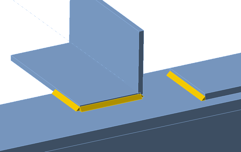
Esempi di saldature per le quali viene verificato lo spessore massimo sono riportati nella figura seguente.
La dimensione minima della saldatura a cordone d'angolo viene verificata secondo la Tabella J2.4:
- Per \(t_p \le 1/4\,\textrm{in}\) la dimensione della saldatura deve essere maggiore o uguale a 1/8 in.
- Per \(1/4\,\textrm{in}< t_p \le 1/2\,\textrm{in}\) la dimensione della saldatura deve essere maggiore o uguale a 3/16 in.
- Per \(1/2\,\textrm{in}< t_p \le 3/4\,\textrm{in}\) la dimensione della saldatura deve essere maggiore o uguale a 1/4 in.
- Per \(3/4\,\textrm{in}< t_p\) la dimensione della saldatura deve essere maggiore o uguale a 5/16 in.
dove \(t_p\) è lo spessore della piastra più sottile.
La lunghezza minima delle saldature a cordone d'angolo non deve essere inferiore a quattro volte la dimensione della saldatura secondo J2.2b (c).
La gola efficace minima della saldatura a piena penetrazione parziale (PJP) è determinata secondo AISC 360-22 – Tabella J2.3:
| Spessore della parte più sottile del giunto [in.] | Gola efficace minima [in.] |
| \(t_p \le 0.25\) | 0.1250 |
| \(0.25 < t_p \le 0.50\) | 0.1875 |
| \(0.50 < t_p \le 0.75\) | 0.2500 |
| \(0.75 < t_p \le 1.50\) | 0.3125 |
| \(1.50 < t_p \le 2.25\) | 0.3750 |
| \(2.25 < t_p \le 6\) | 0.5000 |
| \(6.00 < t_p\) | 0.6250 |
Ancoraggi
L'interasse tra gli ancoraggi deve essere maggiore di quattro volte il diametro dell'ancoraggio secondo ACI 318-14 – 17.7.1.
La distanza minima dal bordo della piastra segue le regole per i bulloni.
Prova oggi l'ultima versione di IDEA StatiCa
Classificazione dei giunti in acciaio (AISC)
I giunti sono classificati in base alla rigidezza del giunto in:
- Rigido – giunti con variazione trascurabile degli angoli originali tra gli elementi,
- Semi-rigido – giunti che si assume abbiano la capacità di fornire un grado affidabile e noto di vincolo flessionale,
- Semplice – giunti che non sviluppano momenti flettenti.
I giunti sono classificati secondo il commentario AISC 360-16, Cl. B3.4.
- Rigido – \( \frac{S_{j,ini} L_b}{E I_b} \ge 20 \)
- Semi-rigido – \( 2 < \frac{S_{j,ini} L_b}{E I_b} < 20 \)
- Semplice – \( \frac{S_{j,ini} L_b}{E I_b} \le 2 \)
dove:
- Sj,ini – rigidezza iniziale del giunto; la rigidezza del giunto è assunta lineare fino a 2/3 di Mj,Rd
- Lb – lunghezza teorica dell'elemento analizzato
- E – modulo di elasticità di Young
- Ib – momento di inerzia dell'elemento analizzato
- Mj,Rd – resistenza di progetto a momento del giunto
Progettazione a capacità (AISC)
La progettazione a capacità è una parte della verifica sismica e garantisce che il giunto abbia una sufficiente capacità di deformazione.
L'obiettivo della progettazione a capacità è confermare che un edificio subisca un comportamento duttile controllato al fine di evitare il collasso in un terremoto di progetto. Si prevede che la cerniera plastica compaia nell'elemento dissipativo e tutti gli elementi non dissipativi del giunto devono essere in grado di trasferire in sicurezza le forze dovute alla plasticizzazione nell'elemento dissipativo. L'elemento dissipativo è solitamente una trave in un telaio resistente ai momenti, ma può essere anche, ad esempio, una piastra d'estremità. Il coefficiente di sicurezza non viene utilizzato per gli elementi dissipativi. Due fattori sono assegnati alla resistenza allo snervamento dell'elemento dissipativo:
- Ry – rapporto tra la resistenza allo snervamento probabile e quella minima – AISC 341-16 – Tabella A3.1; modificabile nei materiali
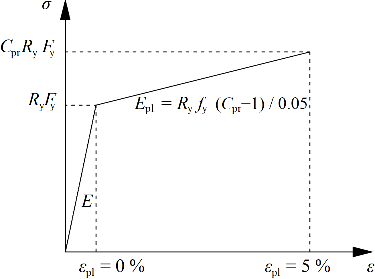
- \( C_{pr}=\frac{F_y+F_u}{2\bullet F_y} \le 1.2 \) – fattore di incrudimento
La resistenza ultima dell'elemento dissipativo è aumentata dal fattore Rt – rapporto tra la resistenza a trazione probabile e quella minima – AISC 341-16 – Tabella A3.1; modificabile nei materiali
Il diagramma del materiale viene modificato secondo la figura seguente:
La resistenza aumentata dell'elemento dissipativo consente l'inserimento di carichi che causano la comparsa della cerniera plastica nell'elemento dissipativo. Nel caso di un telaio resistente ai momenti con la trave come elemento dissipativo, la trave deve essere caricata da My = CprRyFyZpl,y e dalla corrispondente forza di taglio Vz = –2 My / Lh, dove:
- Fy – resistenza caratteristica allo snervamento
- Zpl,y – modulo di resistenza plastico della sezione
- Lh – distanza tra le cerniere plastiche sulla trave
Nel caso di un giunto asimmetrico, la trave deve essere caricata sia da momenti flettenti positivi che negativi e dalle corrispondenti forze di taglio.
Le piastre degli elementi dissipativi sono escluse dalla verifica normativa.