Model Entities
We include the following in the Model entity category in the Detail application:
- Members
- Supports
- Load transfer devices
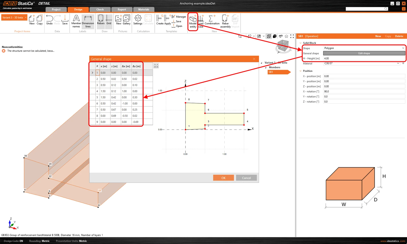
Only one Member can be input, which can be defined as a Rectangle or Polygon shape. A rectangular shape is defined by three dimensions, while for the Polygon option, the shape in 2D space is entered into a table using coordinates, which can then be extracted into space. To define the general shape of a polygon, individual coordinates can be filled in the table, or a copy-paste from a spreadsheet program (such as Microsoft Excel) can be used.
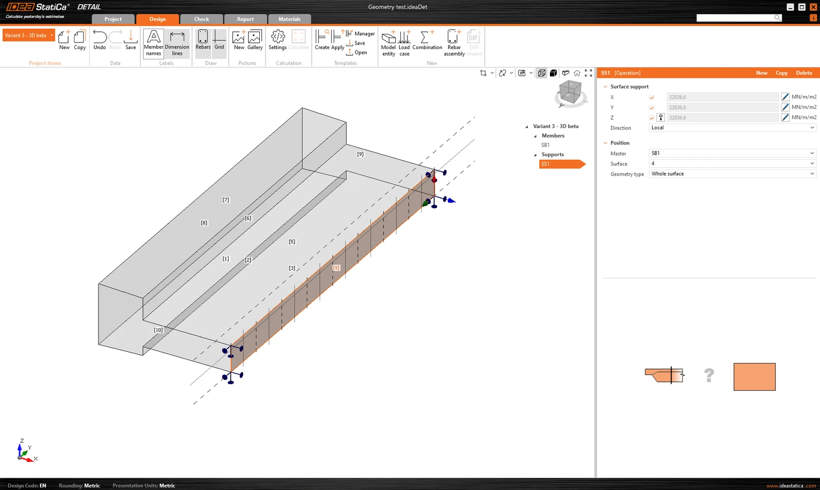
Surface support is used to support the model. This type of support can be specified in two ways - two Geometry types.
- Whole surface
- Polyline
In both cases, you need to choose a reference surface and of course, define degrees of freedom. The support can be defined as elastic and the Compression-only type can be used for a direction perpendicular to the specified surface. In the following figure, we can see the support input on the Whole surface number 4 and the Compression-only option turned off.
For the second option of polyline input, the same table is available as for Members input. Again, you can use the copy-paste functionality or enter the coordinates manually. The entered shape can be moved along the reference surface using X and Y coordinates or rotated by entering an angle.
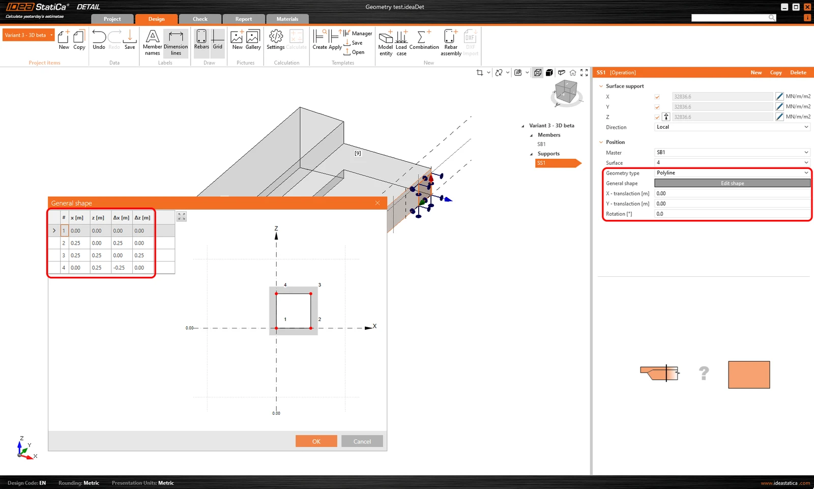
Note that it is possible to specify a polyline so that the origin of the coordinates is at the center of gravity of the desired shape. The position will then be referenced by the X and Y coordinates to that center of gravity.
Stiffness of supports for foundations
During modeling, we can consider two cases. If we model anchorage to structure, the supports can be assumed to be infinitely stiff.
In the case of anchorage into a foundation block, the stiffness must be defined correctly. In addition, the supports must be defined as compression-only.
The values in the z-direction (stiffness Kz) are taken from the literature according to the appropriate soil type. A specific example can be found in the tutorial.
The values depend on the recommendations of the relevant regional literature. Alternatively, the values are obtained from the geotechnical engineer.
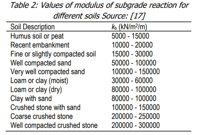
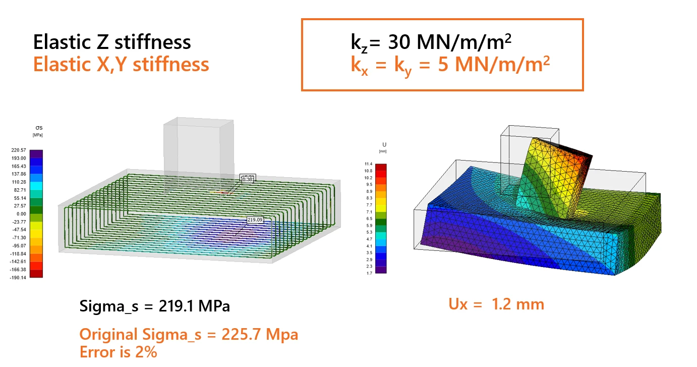
In the horizontal directions (Kx and Ky), the situation is less straightforward. Our general recommendation is to use a value of approximately 1/10 of Kz together with engineering judgment.
A more accurate approach would be to use an iterative procedure, from which we derived our recommendation.
First, set Kx and Ky to very low values (for computational reasons, it is not advisable to set the value directly to zero), but for example 0.1, and examine the reinforcement stresses.
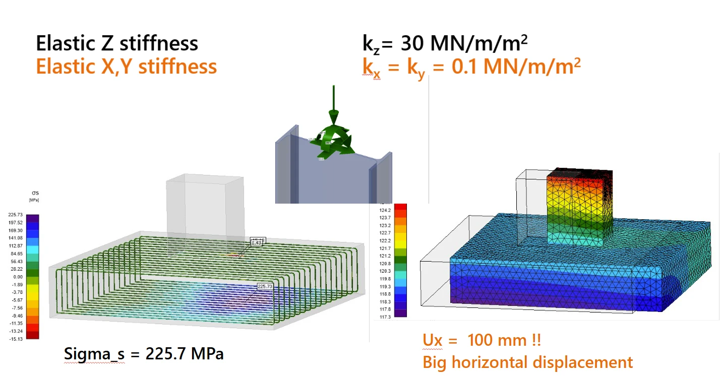
Since these low values result in unrealistic displacements, the stiffness should be gradually increased to better reflect reality. The goal is to achieve more realistic displacement values while keeping the reinforcement tensile stress at the bottom edge close to the original value, with a deviation of less than 5%.