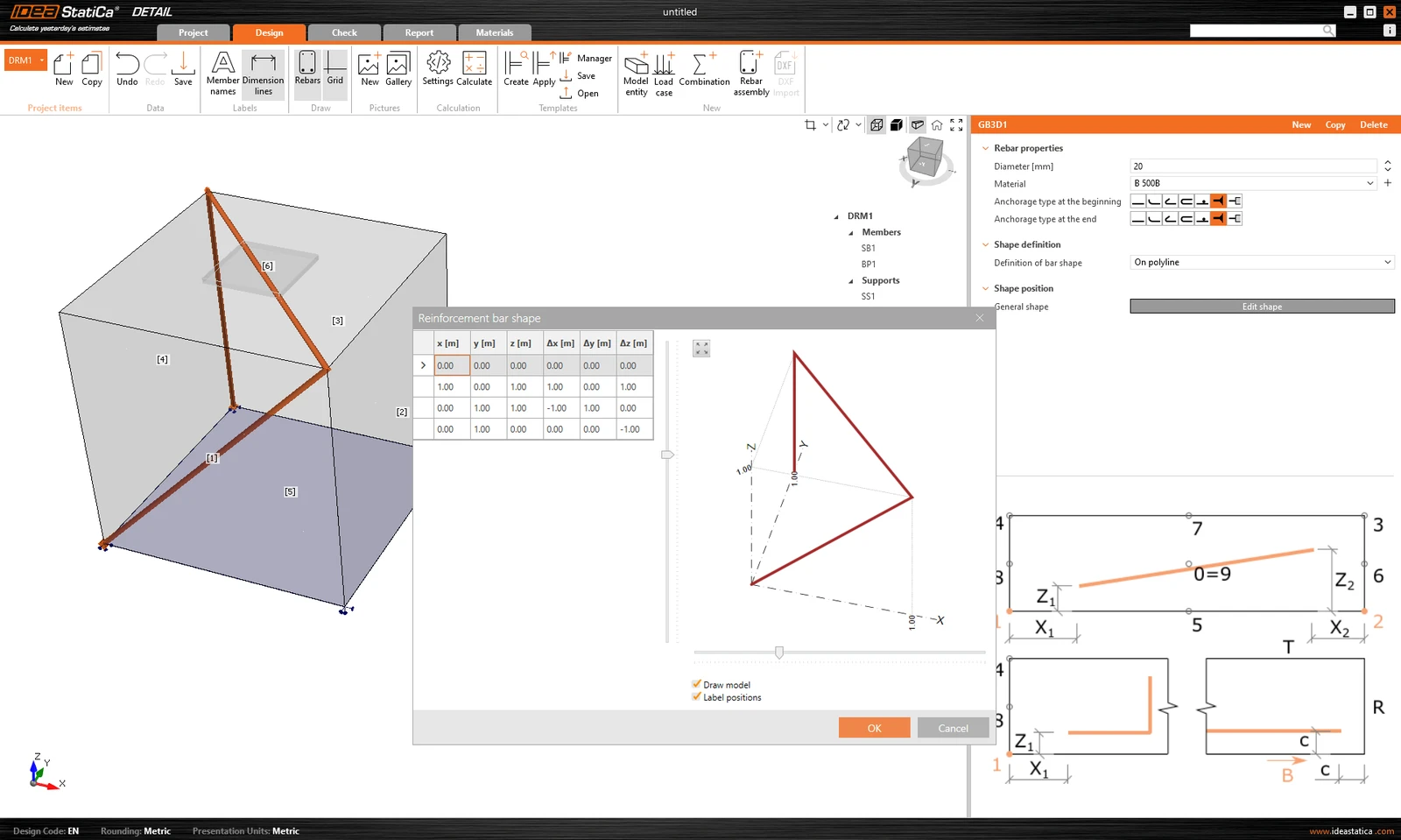
The model can be reinforced with Group of bars 3D. This reinforcement type contains many options, which we will go through in the following text. Thus, 4 types of Definitions of bar shape can be specified:
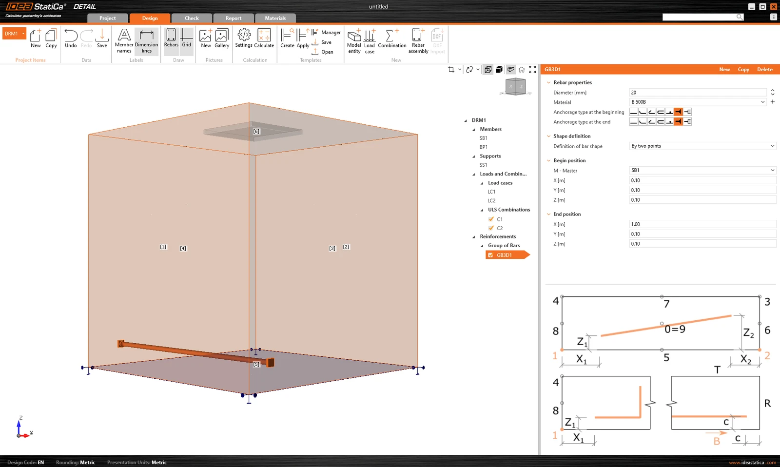
- By two points
- On surface edge
- On surface edge on more edges
- On polyline
For each of these elements you can of course specify the diameter and material including the Anchorage type at the beginning and at the end of the bars.
Shape definition of the bar By two points is self-explanatory. You need to input two sets of cartesian coordinates X, Y, Z.
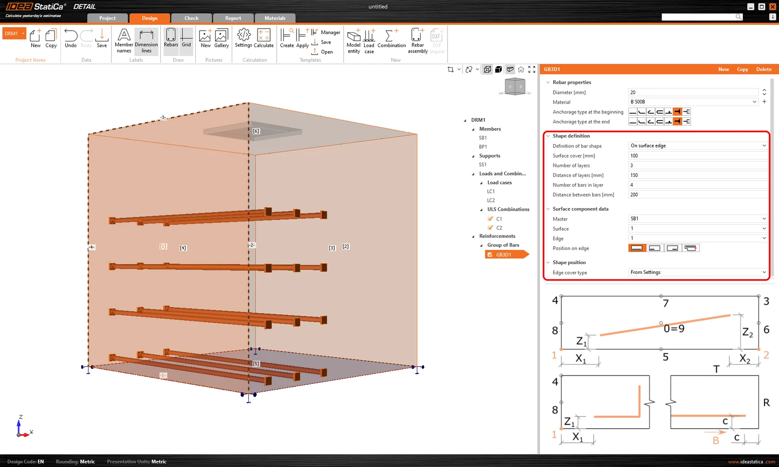
Definition On surface edge offers a lot of controls to position rebars to the required location. You can input reinforcement bars in more layers with more rebars in one layer with specified distances between bars in and between layers. Of course, it is also necessary to specify the reference surface and edge. Next, you must specify Surface cover, which defines the distance from the reference surface (from surface [1] in the figure below) and Edge cover, which defines the distance of the inserts from the side surfaces (from surfaces [4], [5], and [2] in the figure below), can be specified as From settings or User input. The default cover value (From settings) for the active Project item can be found in the first item of the tree (by default called DRM1) item of the tree. This was defined at the beginning of this article. The edge cover can be set as a unique value for each Group of bars.
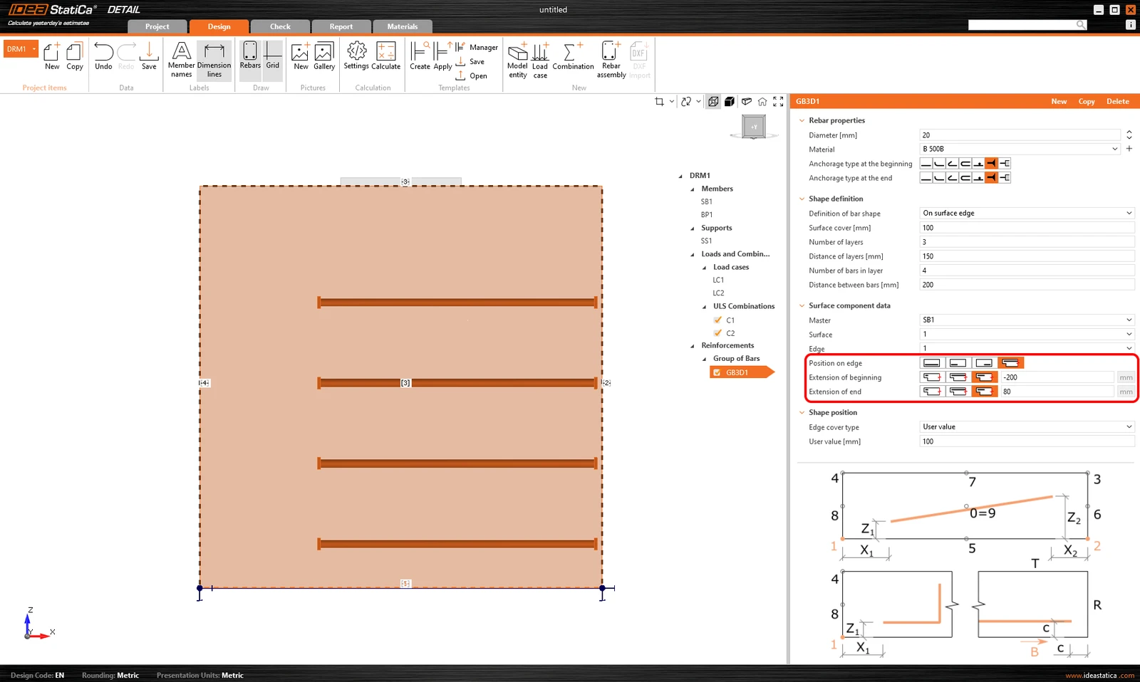
Lastly, Position on edge can be edited for this type of entry. For example, as shown in the figure below, it is possible to specify the reinforcement so that the User-defined Edge cover is applied only to the bottom surface [5]. The side surfaces are controlled by the Extension of the beginning and end.
Another type of definition is On surface endge on more edges. Here it is possible to specify a list of edges or surfaces on which the reinforcement will be placed, together with a list of cover layers for each surface as shown in the following figure.
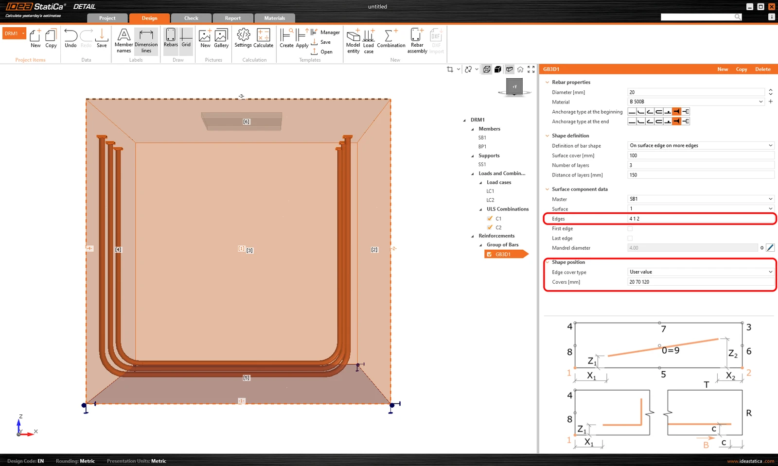
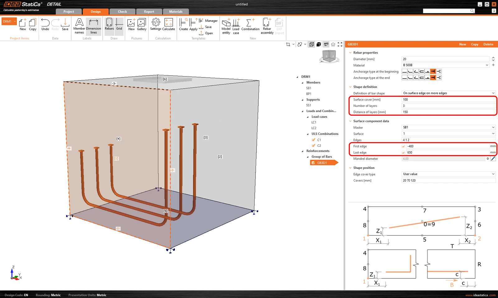
The cover can also be specified using the From settings option, as with the previous one. Again, it is possible to offset the reinforcement from the reference surface using the Surface cover and specify the Number and Distance of layers. It is also possible to lengthen or shorten the ends from the First edge and Last edge.
The last way of defining the reinforcement is On polyline. As in the model entities mentioned above, the reinforcement can be specified using a list of coordinates copied from a spreadsheet program. In this case, a 3D scene with the reinforcement displayed is additionally available for better orientation, allowing rotations around two axes.