Vnitřní síly v ocelových přípojích
Koncové síly prvku z modelu rámu jsou přeneseny na konce segmentů prvků. Při přenosu jsou respektovány excentricity prvků způsobené návrhem styčníku.
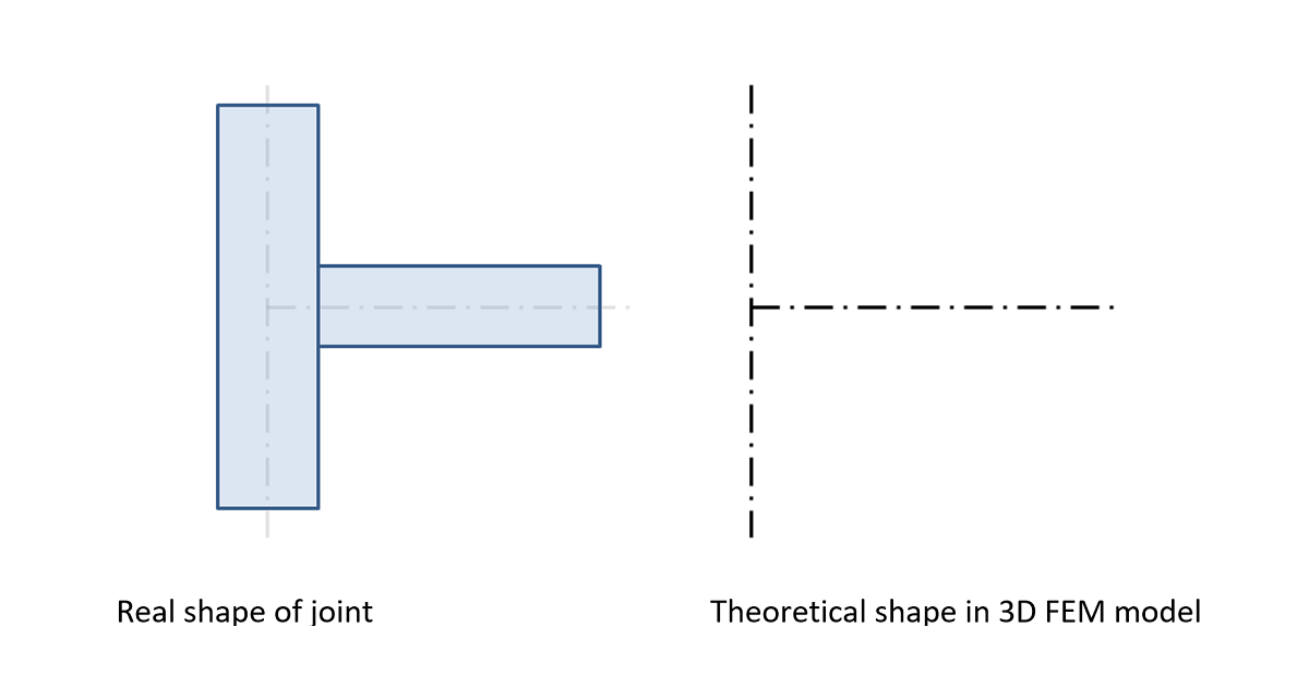
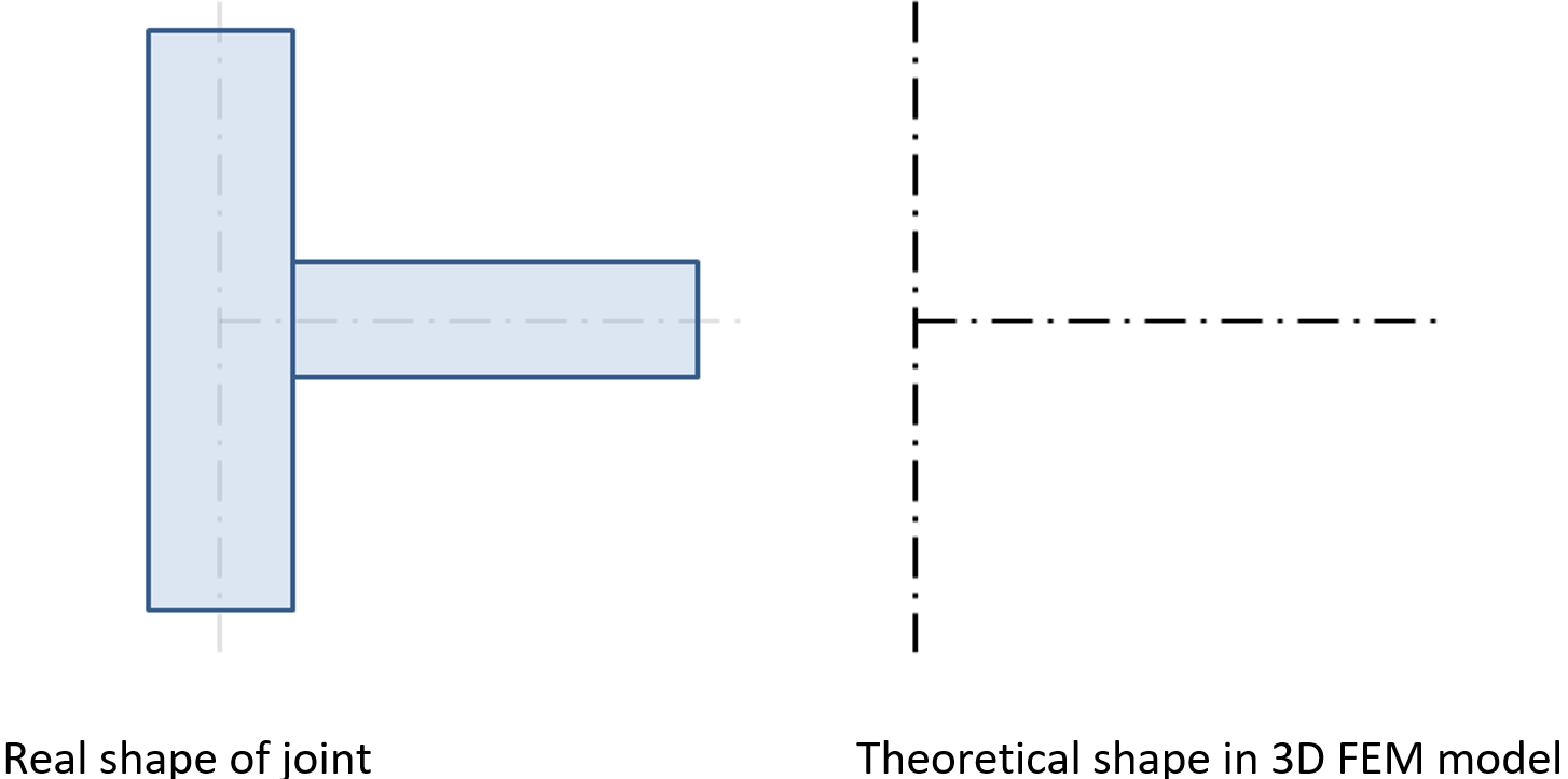
Analytický model vytvořený metodou CBFEM velmi přesně odpovídá skutečnému styčníku, zatímco analýza vnitřních sil je prováděna na výrazně idealizovaném 3D MKP prutinovém modelu, kde jsou jednotlivé nosníky modelovány pomocí střednicových os a styčníky jsou modelovány pomocí nehmotných uzlů.
Styčník svislého sloupu a vodorovného nosníku
Vnitřní síly jsou analyzovány pomocí 1D prvků v 3D modelu. Příklad vnitřních sil je znázorněn na následujícím obrázku.
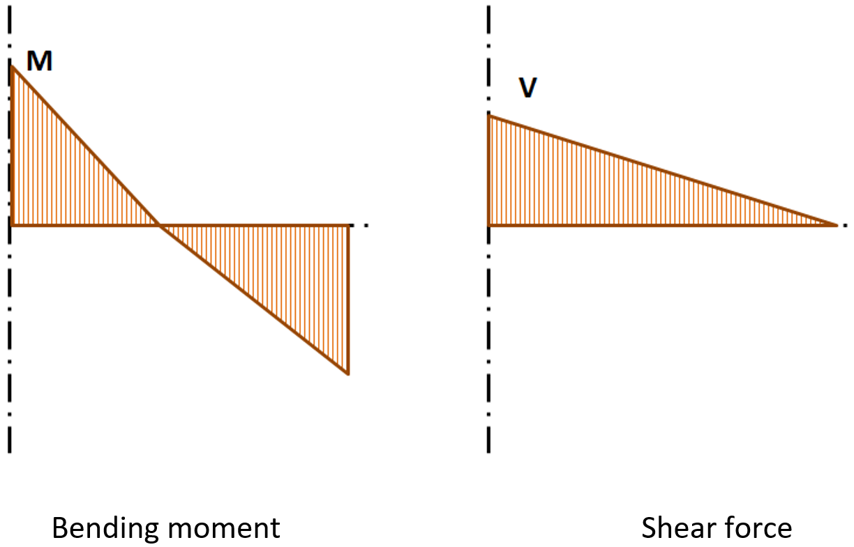
Vnitřní síly ve vodorovném nosníku; M a V jsou koncové síly ve styčníku
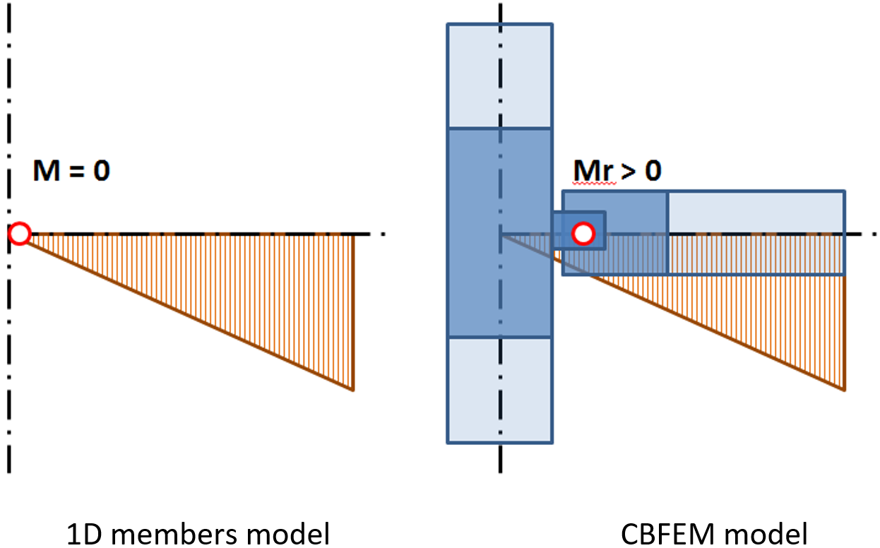
Pro návrh styčníku (přípoje) jsou důležité účinky, které prvek vyvozuje na styčník. Tyto účinky jsou znázorněny na následujícím obrázku:
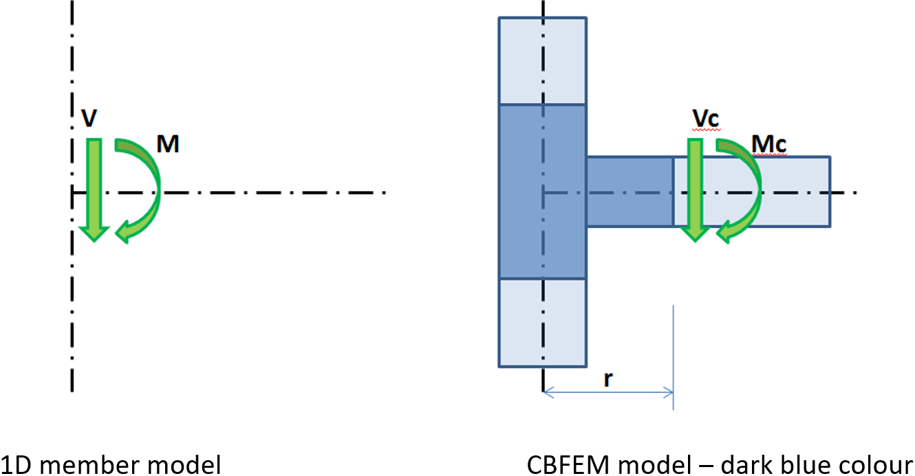
Účinky prvku na styčník; model CBFEM je zobrazen tmavě modrou barvou
Moment M a posouvající síla V působí v teoretickém styčníku. Bod teoretického styčníku v modelu CBFEM neexistuje, a proto zde nelze zatížení aplikovat. Model musí být zatížen účinky M a V, které musí být přeneseny na konec segmentu ve vzdálenosti r
Mc = M – V ∙ r
Vc = V
V modelu CBFEM je koncový průřez segmentu zatížen momentem Mc a silou Vc.
Při návrhu styčníku musí být určena a respektována jeho skutečná poloha vůči teoretickému bodu styčníku. Vnitřní síly v poloze skutečného styčníku se většinou liší od vnitřních sil v teoretickém bodě styčníku. Díky přesnému modelu CBFEM je návrh prováděn na redukované síly – viz moment Mr na následujícím obrázku:
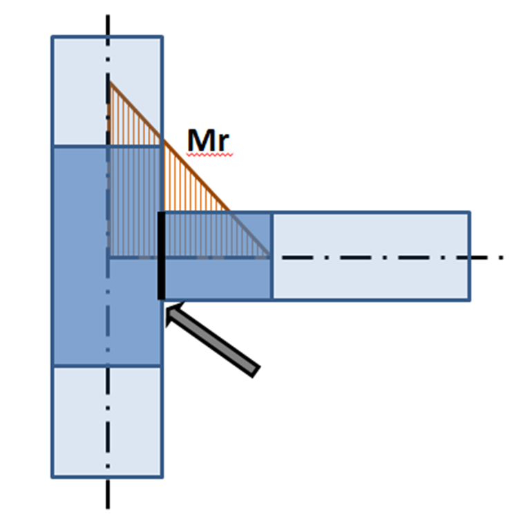
Ohybový moment na modelu CBFEM: šipka ukazuje na skutečnou polohu přípoje
Při zatěžování styčníku musí být respektováno, že řešení skutečného styčníku musí odpovídat teoretickému modelu použitému pro výpočet vnitřních sil. To je splněno pro tuhé styčníky, ale situace může být zcela odlišná pro klouby.
Poloha kloubu v teoretickém 3D MKP modelu a ve skutečné konstrukci
Z předchozího obrázku vyplývá, že poloha kloubu v teoretickém modelu 1D prvků se liší od skutečné polohy v konstrukci. Teoretický model neodpovídá skutečnosti. Při aplikaci vypočtených vnitřních sil je na posunutý styčník aplikován významný ohybový moment a navrhovaný styčník je předimenzovaný nebo jej nelze vůbec navrhnout. Řešení je jednoduché – oba modely musí odpovídat. Buď musí být kloub v modelu 1D prvků definován ve správné poloze, nebo musí být posouvající síla posunuta tak, aby byl moment v poloze kloubu nulový.
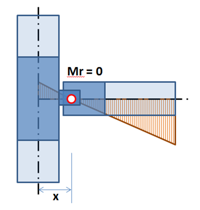
Posunutý průběh ohybového momentu na nosníku: nulový moment je v poloze kloubu
Posun posouvající síly lze definovat v tabulce pro zadání vnitřní síly.
Poloha účinku zatížení má velký vliv na správný návrh přípoje. Aby se předešlo veškerým nedorozuměním, umožňujeme uživateli vybrat ze tří možností – Uzel / Šrouby / Poloha.
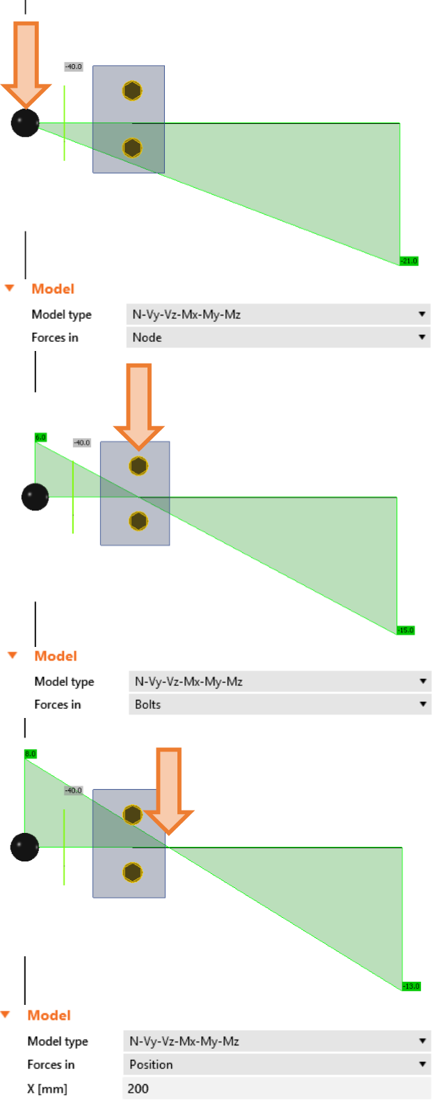
Při výběru možnosti Uzel jsou síly aplikovány na konec vybraného prvku, což je obvykle v teoretickém uzlu, pokud není v geometrii nastaven odsazení vybraného prvku.
Import zatížení z programů MKP
IDEA StatiCa umožňuje import vnitřních sil z programů MKP třetích stran. Programy MKP používají obálku vnitřních sil z kombinací. IDEA StatiCa Connection je program, který řeší ocelový styčník nelineárně (elasticko-plastický materiálový model). Proto nelze použít obálkové kombinace. IDEA StatiCa vyhledává extrémy vnitřních sil (N, Vy, Vz, Mx, My, Mz) ve všech kombinacích na koncích všech prvků připojených ke styčníku. Pro každou takovou extrémní hodnotu jsou použity také všechny ostatní vnitřní síly z dané kombinace ve všech ostatních prvcích. IDEA StatiCa určuje nejhorší kombinaci pro každou komponentu (plech, svar, šroub atd.) v přípoji.
Uživatel může tento seznam zatěžovacích stavů upravit. Může pracovat s kombinacemi v průvodci (nebo BIM), nebo může některé případy přímo smazat v IDEA StatiCa Connection.
Upozornění!
Při importu je nutné zohlednit nevyvážené vnitřní síly. K tomu může dojít v následujících případech:
- Uzlová síla byla aplikována v poloze zkoumaného uzlu. Software nemůže zjistit, který prvek by měl tuto uzlovou sílu přenést, a proto není v analytickém modelu zohledněna. Řešení: Nepoužívejte uzlové síly v globální analýze. V případě potřeby musí být síla ručně přidána k vybranému prvku jako normálová nebo posouvající síla.
- Zatížený neocelový (obvykle dřevěný nebo betonový) prvek je připojen ke zkoumanému uzlu. Takový prvek není v analýze uvažován a jeho vnitřní síly jsou v analýze ignorovány. Řešení: Nahraďte betonový prvek betonovým blokem a kotvením.
- Uzel je součástí desky nebo stěny (obvykle betonové). Deska nebo stěna není součástí modelu a její vnitřní síly jsou ignorovány. Řešení: Nahraďte betonovou desku nebo stěnu betonovým blokem a kotvením.
- Některé prvky jsou ke zkoumanému uzlu připojeny prostřednictvím tuhých vazeb. Takové prvky nejsou zahrnuty v modelu a jejich vnitřní síly jsou ignorovány. Řešení: Přidejte tyto prvky do seznamu připojených prvků ručně.
- V softwaru jsou analyzovány seizmické zatěžovací stavy. Většina programů MKP nabízí modální analýzu pro řešení seizmicity. Výsledky vnitřních sil seizmických zatěžovacích stavů poskytují obvykle pouze obálky vnitřních sil v průřezech. Vzhledem k metodě vyhodnocení (odmocnina součtu čtverců – SRSS) jsou vnitřní síly všechny kladné a není možné najít síly odpovídající vybranému extrému. Není možné dosáhnout rovnováhy vnitřních sil. Řešení: Změňte kladné znaménko některých vnitřních sil ručně.