Koutový svar v přípoji úhelníku
Popis
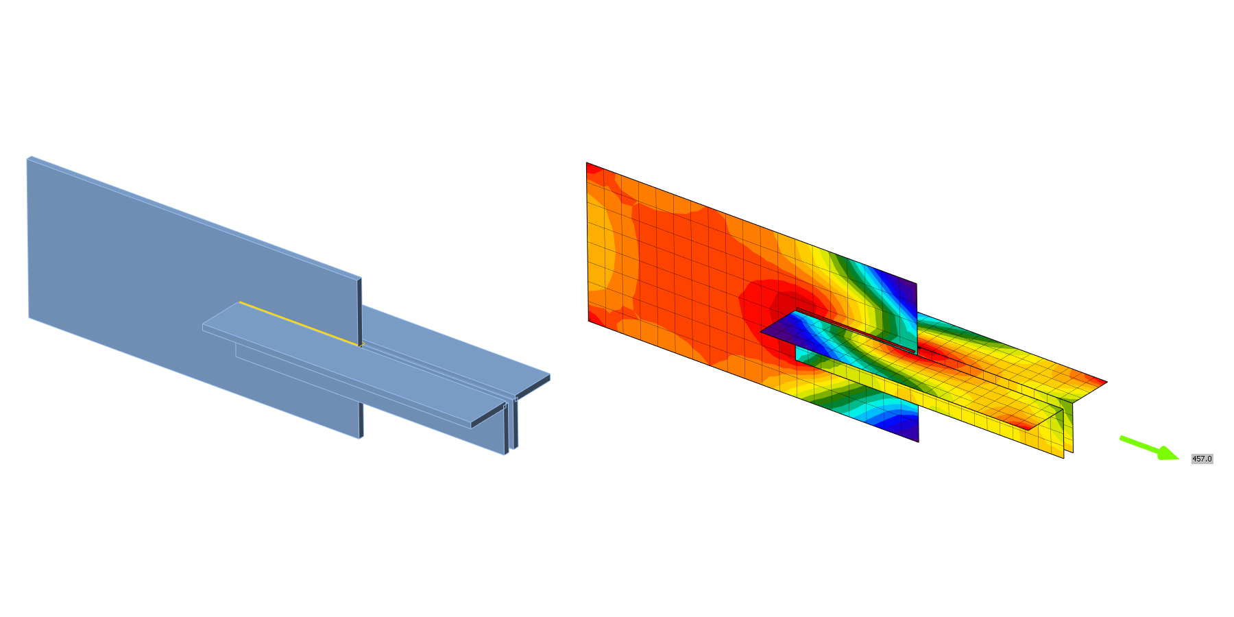
V této kapitole je model koutového svaru v přípoji úhelníku vypočtený metodou konečných prvků na bázi komponent (CBFEM) ověřen pomocí komponentové metody (CM). Úhelník je přivařen k plechu a zatížen normálovou silou. V parametrické studii jsou zkoumány velikost úhelníku a délka svaru.
Analytický model
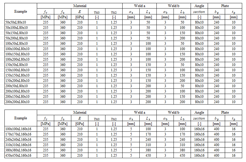
Koutový svar je jediná komponenta zkoumaná v této studii. Svary jsou navrženy podle kapitoly 4 v EN 1993-1-8:2005 tak, aby byly nejslabší komponentou ve styčníku. Návrhová únosnost koutového svaru je popsána v oddíle 4.1. Přehled uvažovaných příkladů a materiálu je uveden v Tab. 4.2.1. Geometrie přípojů s rozměry je znázorněna na Obr. 4.2.1.
Výpočet komponentovou metodou
Tento ruční výpočet zanedbává přídavný moment svaru, který vzniká v důsledku přerozdělení sil do částí průřezu L podle EN 1993-1-8 (4.13).
\[\sqrt{ \sigma_{\perp}^2 + 3 \cdot \left( \tau_{\perp}^2 + \tau_{\parallel}^2\right)} \leq \frac{f_u}{\beta_{\mathrm{w}} \cdot \gamma_{\mathrm{M2}}}\]
\[\sigma_{\perp} = \tau_{\perp} = 0 \]
\[ \tau_{\parallel} = \frac{V}{l \cdot a}\]
\[ \sqrt{ 3 \cdot \left( \tau_{\parallel} \right)^2} \leq \frac{f_u}{\beta_{\mathrm{w}} \cdot \gamma_{\mathrm{M2}}}\]
\[ \sqrt{ 3 \cdot \left( \frac{V}{l \cdot a}\right)^2} \leq \frac{f_u}{\beta_{\mathrm{w}} \cdot \gamma_{\mathrm{M2}}}\]
\[ V = \frac{f_u \cdot l \cdot a \cdot \beta_{\mathrm{Lw1}}}{\beta_{\mathrm{w}} \cdot \gamma_{\mathrm{M2}} \cdot \sqrt{3}} \]
Celková únosnost vypočtená jako součet únosností horního a dolního svaru
\[ V = V_\mathrm{top} + V_\mathrm{bottom} \]
Kde:
\(a\) - účinná výška svaru
\(V\) - posouvající síla působící na nosník
\(l = 2 \cdot L_\mathrm{\dots}\) - délka rovnoběžných svarů
\(\beta_{\mathrm{w}}\) - korelační součinitel převzatý z EN 1993-1-8 Tabulka 4.1
\(\beta_{\mathrm{Lw1}}\) - redukční součinitel pro dlouhé svary, EN 1993-1-8 rovnice 4.9
\(f_u\) - jmenovitá mez pevnosti slabšího spojovaného prvku
\(\gamma_{\mathrm{M2}}\) - dílčí součinitel spolehlivosti pro svary
\[ \textsf{\textit{\footnotesize{Tab. 4.2.1 Přehled příkladů}}}\]
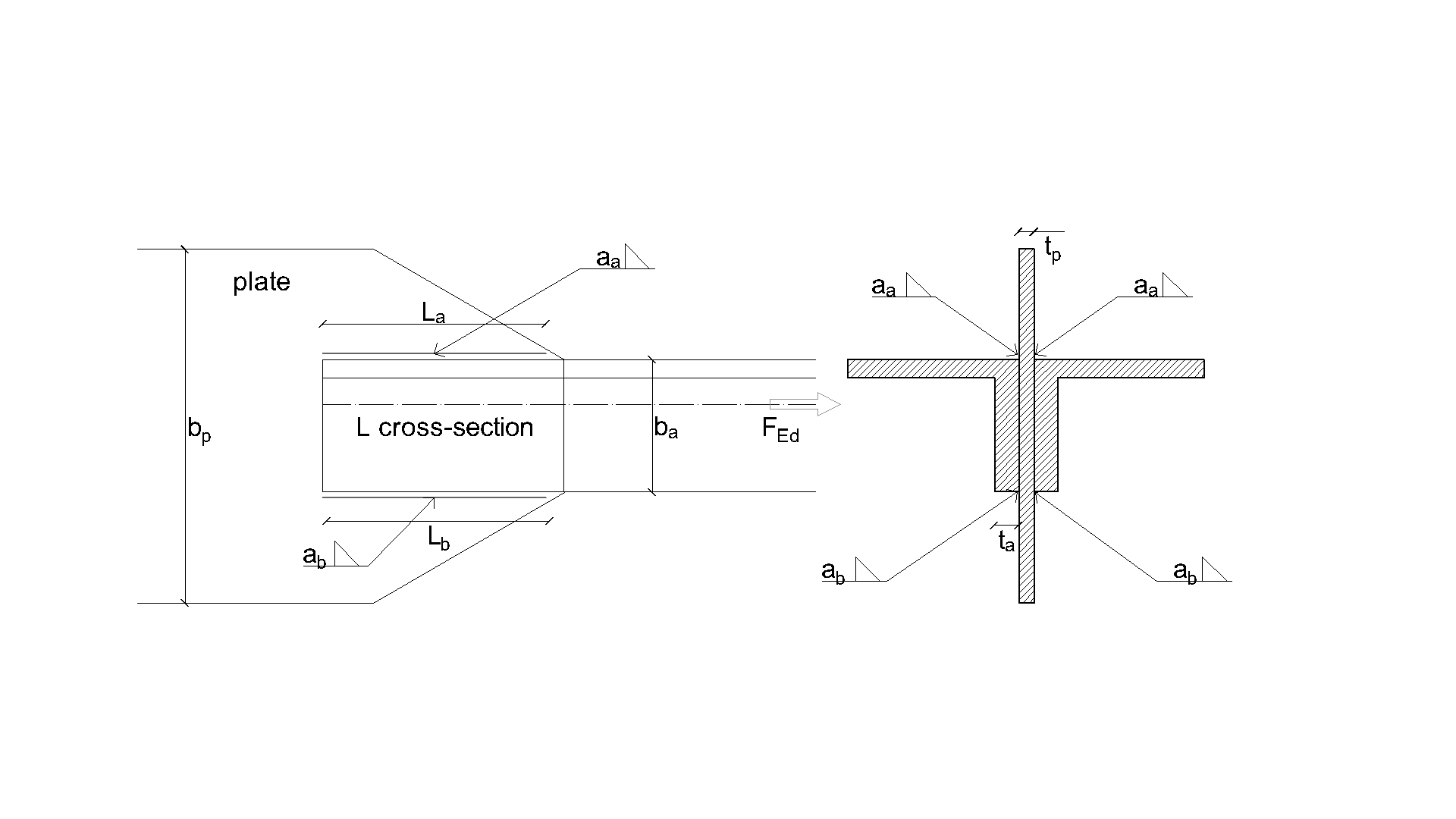
\[ \textsf{\textit{\footnotesize{Obr. 4.2.1 Geometrie přípoje s rozměry}}}\]
Numerický model
Komponenta svaru v CBFEM je popsána v obecném teoretickém pozadí a teoretickém pozadí EN. Model svaru má elasticko-plastický pracovní diagram a napěťové špičky jsou přerozděleny podél délky svaru.
Ověření únosnosti
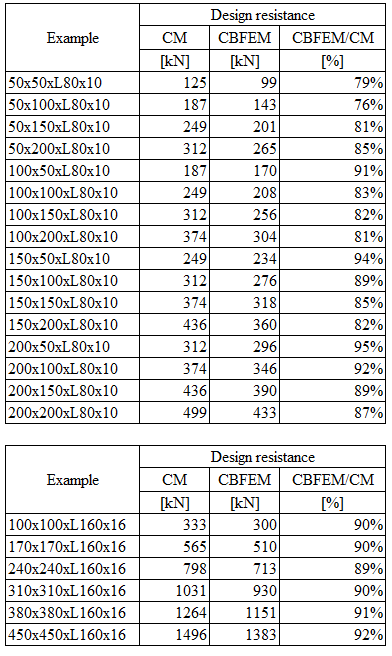
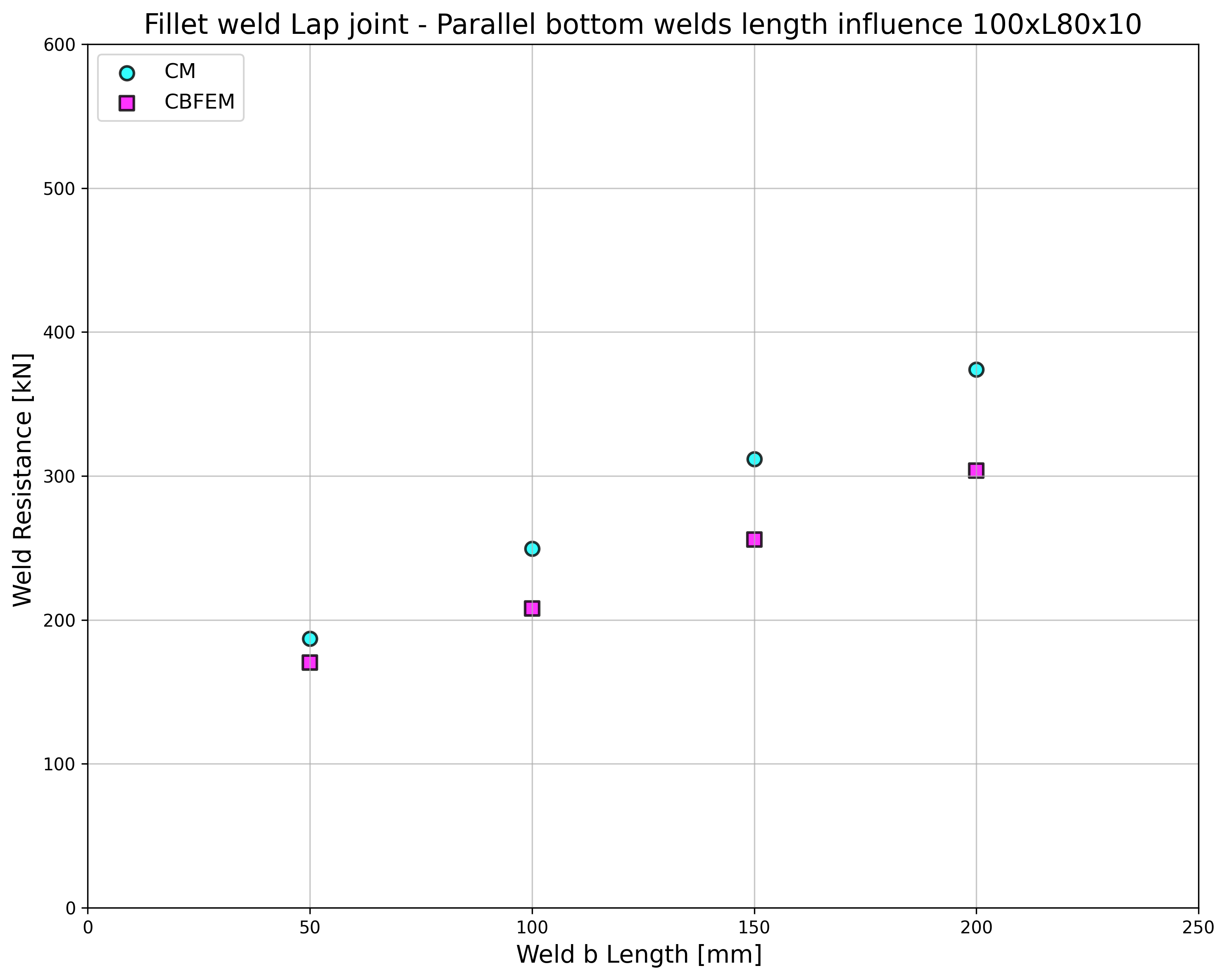
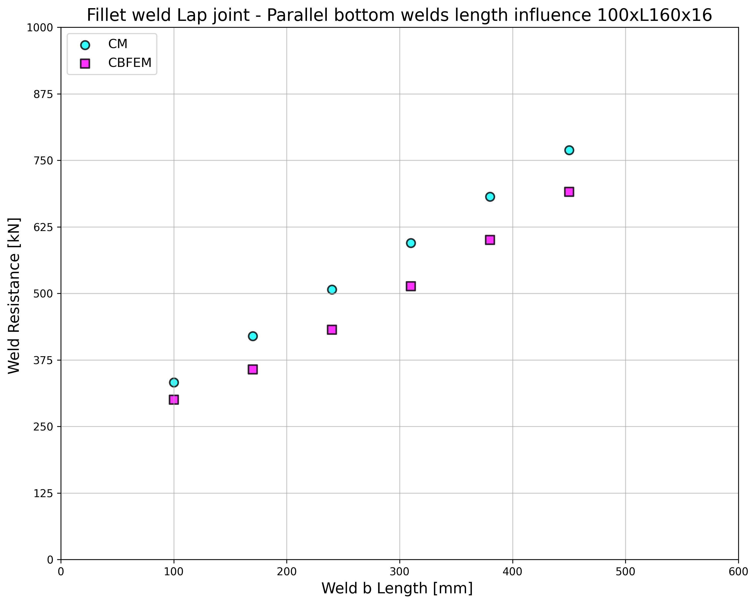
Návrhové únosnosti svarů vypočtené pomocí CBFEM jsou porovnány s výsledky CM; viz Tab. 4.2.2. Jsou studovány dva parametry: délka svaru a průřez úhelníku. Obr. 4.2.2 zobrazuje parametrickou studii délky dolního svaru. Délka horního svaru a v této studii je La=100 mm.
\[ \textsf{\textit{\footnotesize{Tab. 4.2.2 Porovnání CBFEM a CM}}}\]
\[ \textsf{\textit{\footnotesize{a}}}\]
\[ \textsf{\textit{\footnotesize{b}}}\]
\[ \textsf{\textit{\footnotesize{a) Úhelník 80×10 b) Úhelník 160×16}}}\]
\[ \textsf{\textit{\footnotesize{Obr. 4.2.2 Parametrická studie délky dolního svaru b}}}\]
Výsledky CBFEM a CM jsou porovnány a parametrická studie je prezentována. Vliv délky svaru na návrhovou únosnost svařovaného přípoje úhelníku je znázorněn na Obr. 4.2.2. Studie vykazuje dobrou shodu pro všechny konfigurace svarů. Pro ilustraci přesnosti modelu CBFEM jsou výsledky studie shrnuty v diagramu porovnávajícím návrhové únosnosti podle CBFEM a CM; viz Obr. 4.2.3. Výsledky ukazují, že všechny predikce CBFEM jsou na straně bezpečnosti ve srovnání s CM, kde je excentricita zanedbána.
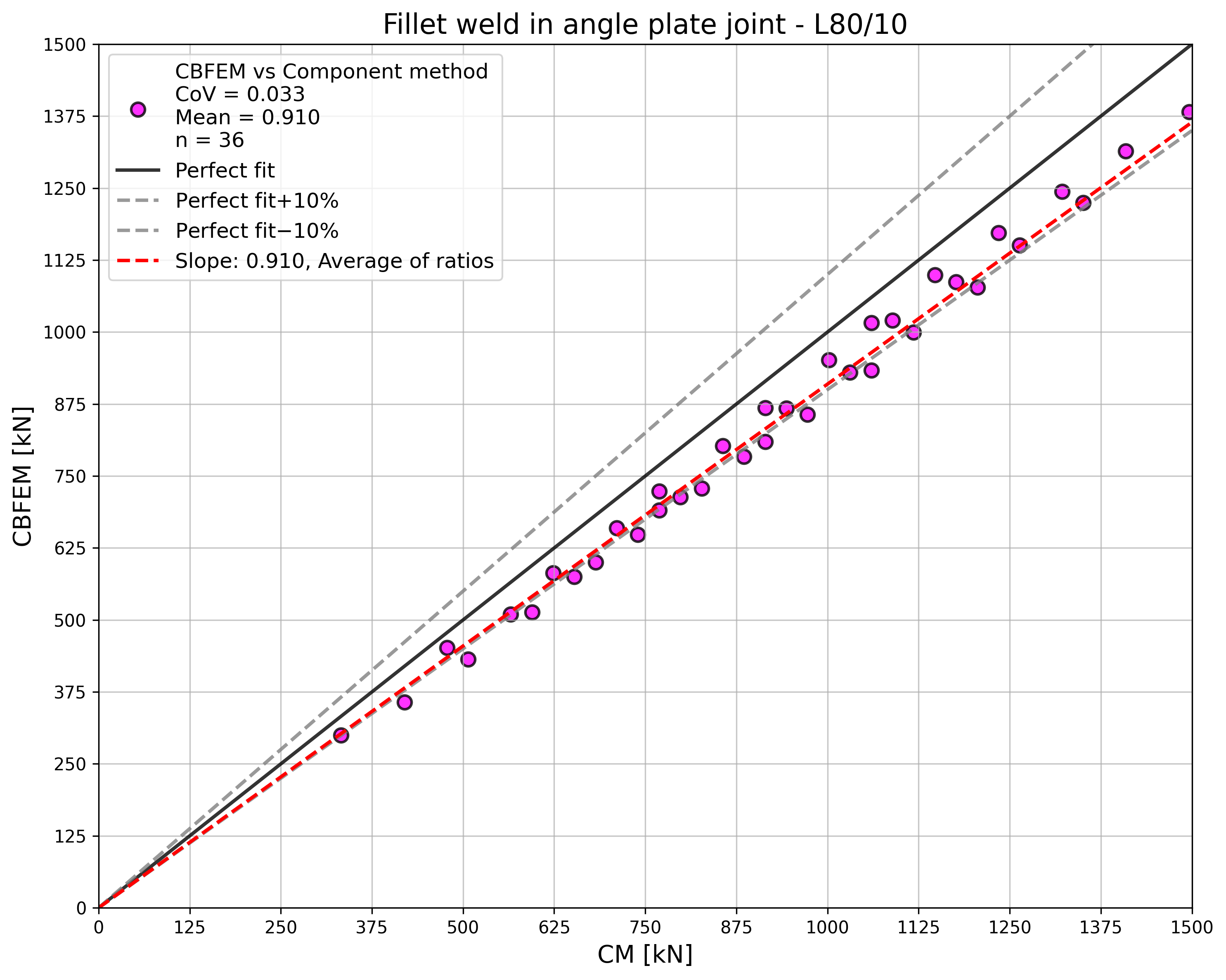
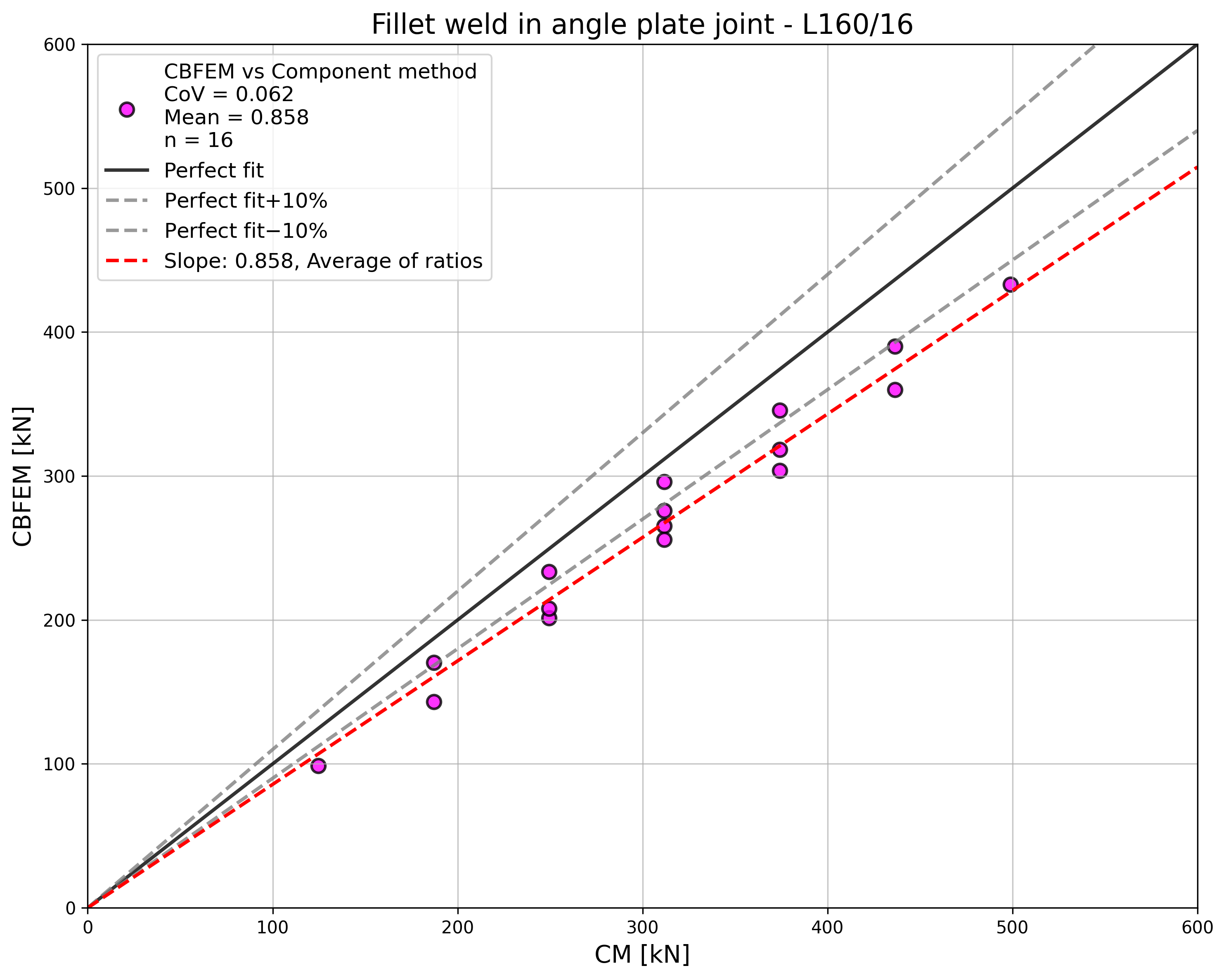
\[ \textsf{\textit{\footnotesize{Obr. 4.2.3 Ověření CBFEM vůči CM}}}\]
Vzorový příklad
Vstupy
Úhelník
- Průřez 2×L80×10
- Vzdálenost mezi úhelníky 16 mm
Plech
- Tloušťka tp = 16 mm
- Šířka bp = 240 mm
Svar, rovnoběžné koutové svary, viz Obr. 4.2.4
- Účinná výška svaru aw = 3 mm
- Délka horního svaru Lw,top = 100 mm
- Délka dolního svaru Lw,bottom = 50 mm
Výstupy
- Návrhová únosnost v tahu FRd = 170 kN (Je třeba poznamenat, že únosnost byla vypočtena pomocí funkce „Stop at limit strain". V důsledku toho může být skutečná únosnost CBFEM mírně vyšší.)
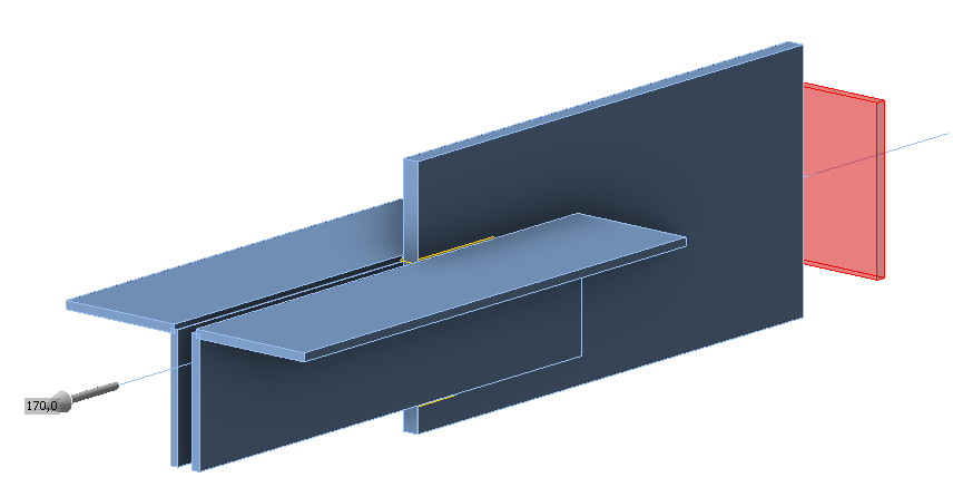
\[ \textsf{\textit{\footnotesize{Obr. 4.2.4 Vzorový příklad svařovaného přípoje úhelníku s rovnoběžnými koutovými svary}}}\]