Szöglemez kapcsolat sarokvarrata
Leírás
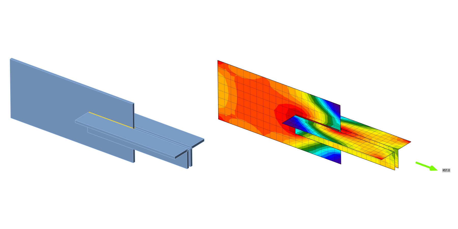
Ebben a fejezetben a szöglemez kapcsolatban lévő sarokvarratok komponens alapú végeselem-módszerrel (CBFEM) számított modelljét ellenőrzik a komponensmódszerrel (CM). Egy szögacélt lemezre hegesztenek és normálerővel terhelik. A szögacél méretét és a varrathosszt érzékenységvizsgálatban tanulmányozzák.
Analitikus modell
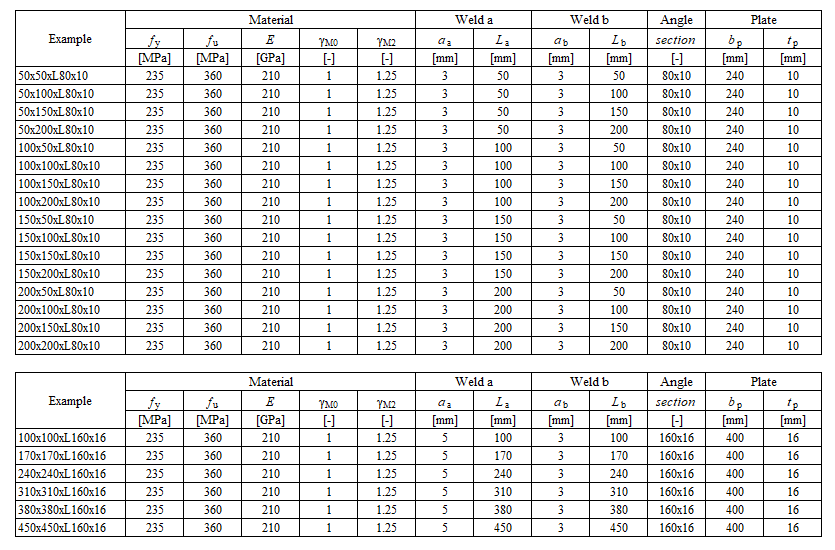
A sarokvarrrat az egyetlen vizsgált komponens a tanulmányban. A varratokat az EN 1993-1-8:2005 4. fejezete szerint tervezik, hogy azok legyenek a kapcsolat leggyengébb komponensei. A sarokvarrrat tervezési ellenállása az 4.1. szakaszban kerül leírásra. A figyelembe vett példák és anyagok áttekintése a 4.2.1. táblázatban található. A kapcsolatok geometriája méretekkel a 4.2.1. ábrán látható.
Komponensmódszer számítása
Ez a kézi számítás elhanyagolja a varrrat további nyomatékát, amely az EN 1993-1-8 (4.13) szerint az L keresztmetszeti részekre történő erőátadás miatt alakul ki.
\[\sqrt{ \sigma_{\perp}^2 + 3 \cdot \left( \tau_{\perp}^2 + \tau_{\parallel}^2\right)} \leq \frac{f_u}{\beta_{\mathrm{w}} \cdot \gamma_{\mathrm{M2}}}\]
\[\sigma_{\perp} = \tau_{\perp} = 0 \]
\[ \tau_{\parallel} = \frac{V}{l \cdot a}\]
\[ \sqrt{ 3 \cdot \left( \tau_{\parallel} \right)^2} \leq \frac{f_u}{\beta_{\mathrm{w}} \cdot \gamma_{\mathrm{M2}}}\]
\[ \sqrt{ 3 \cdot \left( \frac{V}{l \cdot a}\right)^2} \leq \frac{f_u}{\beta_{\mathrm{w}} \cdot \gamma_{\mathrm{M2}}}\]
\[ V = \frac{f_u \cdot l \cdot a \cdot \beta_{\mathrm{Lw1}}}{\beta_{\mathrm{w}} \cdot \gamma_{\mathrm{M2}} \cdot \sqrt{3}} \]
A teljes ellenállás a felső és alsó varratellenállások összegeként számítva
\[ V = V_\mathrm{top} + V_\mathrm{bottom} \]
Ahol:
\(a\) - varrat torokvastagsága
\(V\) - a gerendán ható nyíróerő
\(l = 2 \cdot L_\mathrm{\dots}\) - párhuzamos varratok hossza
\(\beta_{\mathrm{w}}\) - korrelációs tényező az EN 1993-1-8 4.1. táblázatából
\(\beta_{\mathrm{Lw1}}\) - hosszú varrrat csökkentési tényező, EN 1993-1-8 4.9. egyenlet
\(f_u\) - az összekapcsolt gyengébb rész névleges szakítószilárdsága
\(\gamma_{\mathrm{M2}}\) - varratokra vonatkozó részleges biztonsági tényező
\[ \textsf{\textit{\footnotesize{Tab. 4.2.1 Examples overview}}}\]
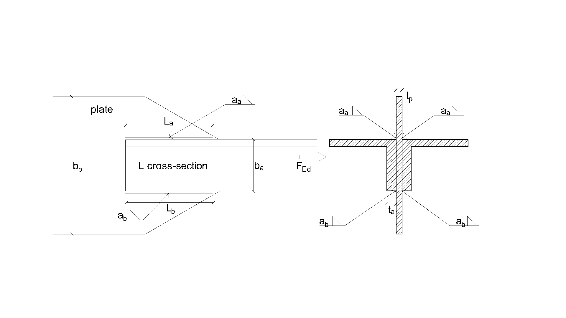
\[ \textsf{\textit{\footnotesize{Fig. 4.2.1 Joint geometry with dimensions}}}\]
Numerikus modell
A CBFEM varratkomponense az Általános elméleti háttér és az EN elméleti háttér dokumentumokban kerül leírásra. A varratmodell rugalmas-képlékeny anyagdiagrammal rendelkezik, és a feszültségcsúcsok a varrathossz mentén újraoszlanak.
Ellenállás ellenőrzése
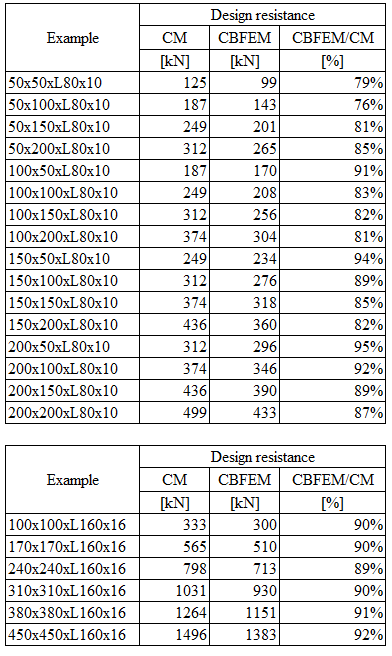
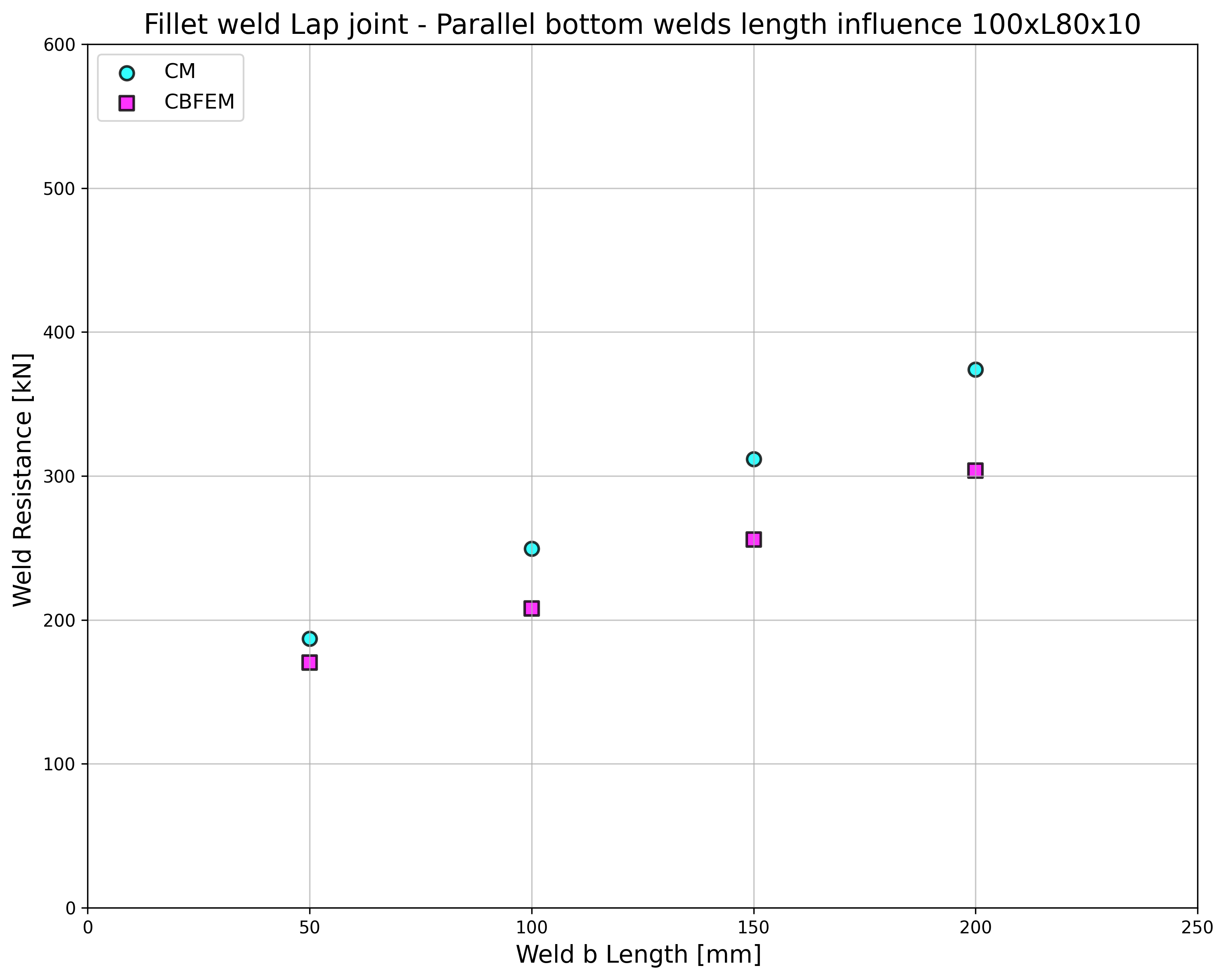
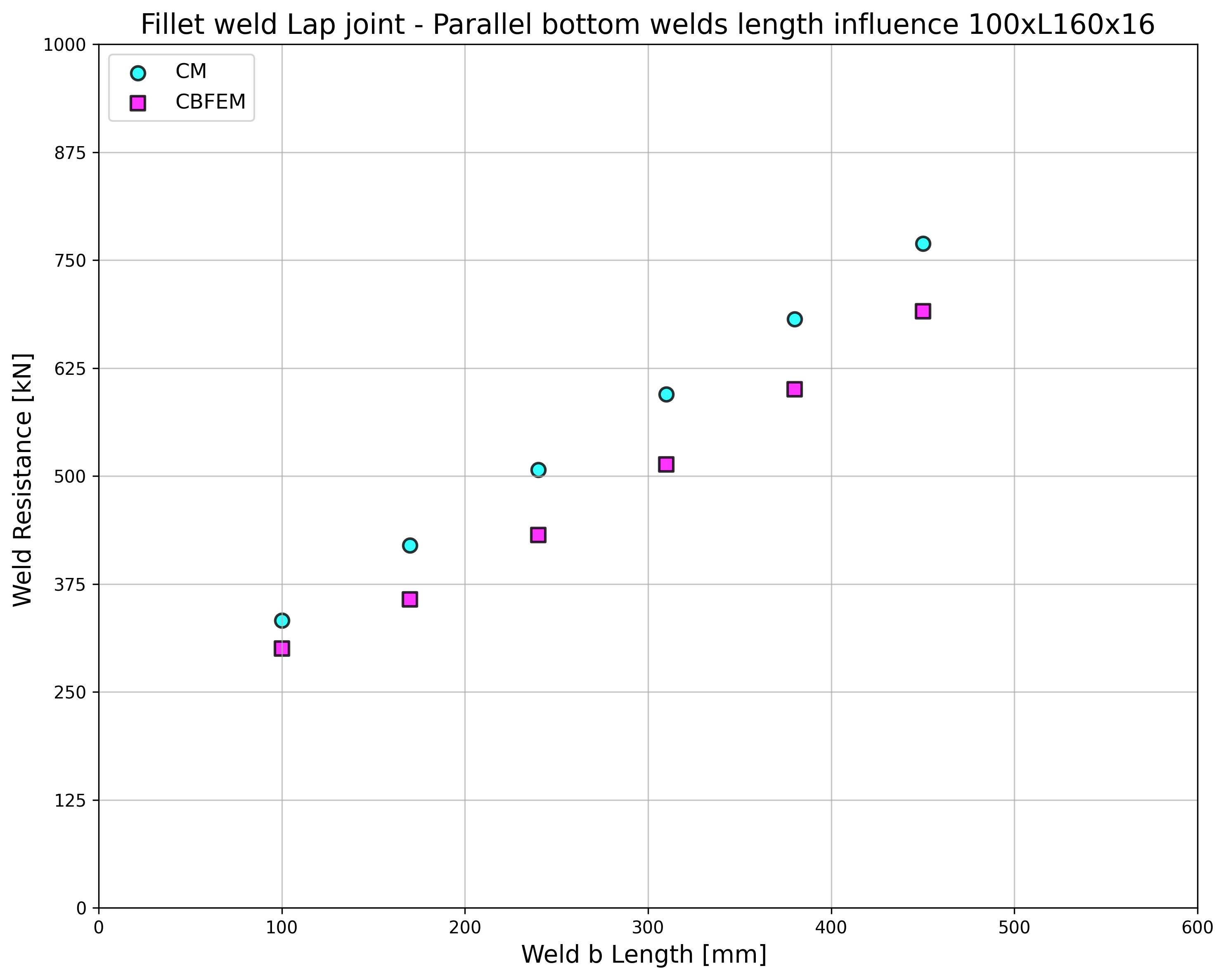
A CBFEM által számított varrat tervezési ellenállásokat a CM eredményeivel hasonlítják össze; lásd a 4.2.2. táblázatot. Két paramétert vizsgálnak: a varrathosszt és a szögacél keresztmetszetét. A 4.2.2. ábra az alsó varrrat b hosszának érzékenységvizsgálatát mutatja. A felső varrrat a hossza a vizsgálatban La=100mm.
\[ \textsf{\textit{\footnotesize{Tab. 4.2.2 Comparison of CBFEM and CM}}}\]
\[ \textsf{\textit{\footnotesize{a}}}\]
\[ \textsf{\textit{\footnotesize{b}}}\]
\[ \textsf{\textit{\footnotesize{a) Angle cleat 80×10 b) Angle cleat 160×16}}}\]
\[ \textsf{\textit{\footnotesize{Fig. 4.2.2 Sensitivity study of bottom weld b length}}}\]
A CBFEM és a CM eredményeit összehasonlítják, és az érzékenységvizsgálat bemutatásra kerül. A varrathossz hatása a hegesztett szögacél kapcsolat tervezési ellenállására a 4.2.2. ábrán látható. A vizsgálat jó egyezést mutat minden varrat-konfigurációra. A CBFEM modell pontosságának szemléltetésére a vizsgálat eredményeit egy diagramban foglalják össze, amely a CBFEM és a CM tervezési ellenállásait hasonlítja össze; lásd a 4.2.3. ábrát. Az eredmények azt mutatják, hogy a CBFEM összes előrejelzése biztonságos oldalon van a CM-hez képest, ahol az excentricitást elhanyagolják.
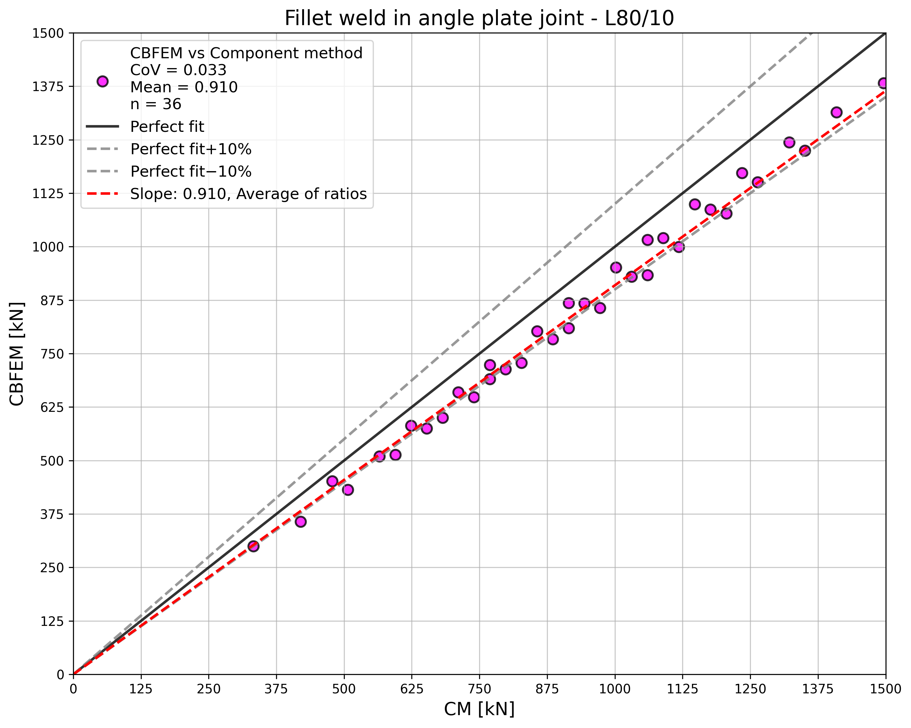
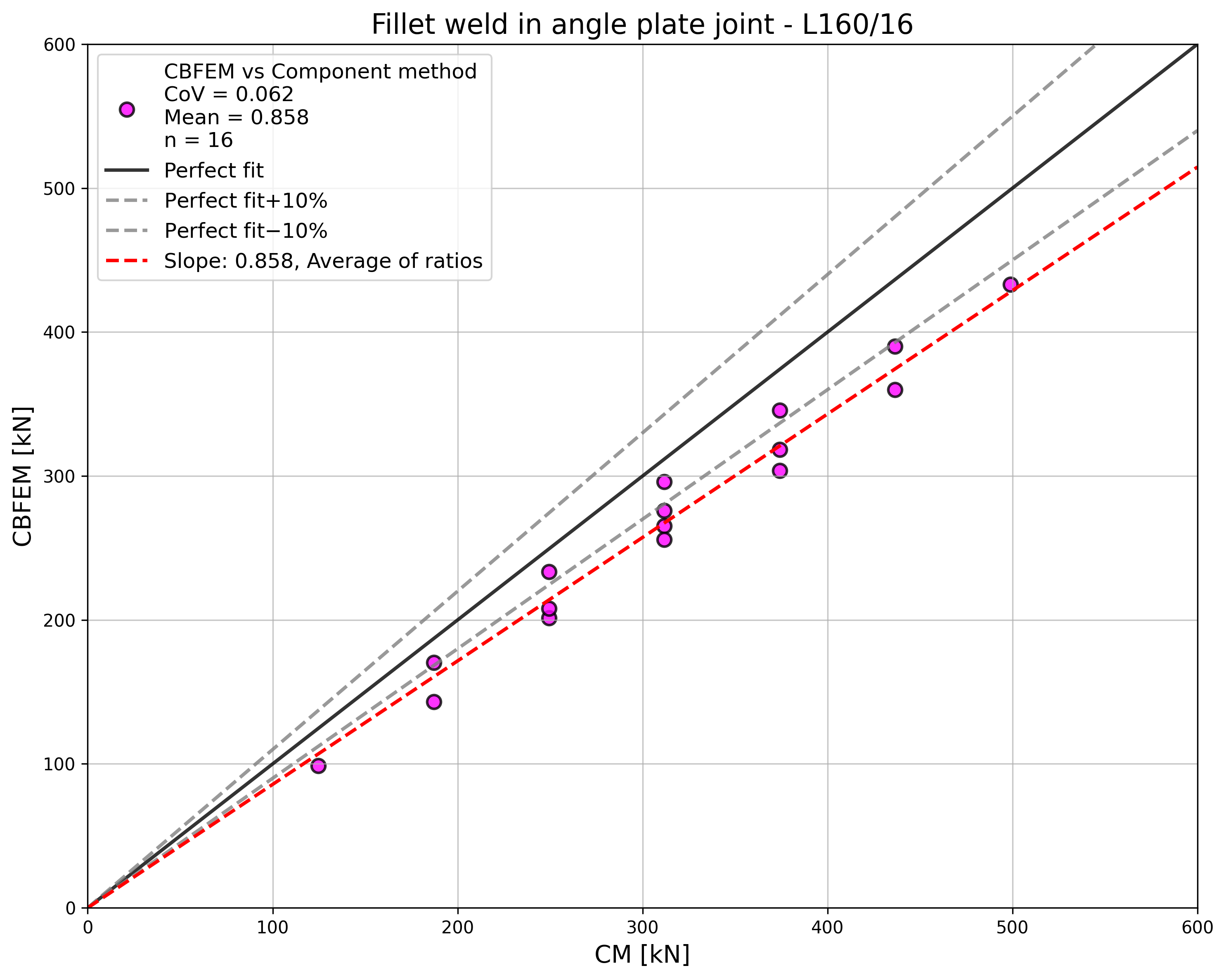
\[ \textsf{\textit{\footnotesize{Fig. 4.2.3 Verification of CBFEM to CM}}}\]
Benchmark példa
Bemeneti adatok
Szögacél
- Keresztmetszet 2×L80×10
- Szögacélok közötti távolság 16 mm
Lemez
- Vastagság tp = 16 mm
- Szélesség bp = 240 mm
Varrrat, párhuzamos sarokvarratok, lásd 4.2.4. ábra
- Torokvastagság aw = 3 mm
- Felső varrrat hossza Lw,top = 100 mm
- Alsó varrrat hossza Lw,bottom = 50 mm
Kimeneti adatok
- Tervezési ellenállás húzásra FRd = 170 kN (Megjegyzendő, hogy az ellenállást a „Megállás határalakváltozásnál" funkció alkalmazásával számították. Következésképpen a tényleges CBFEM ellenállás marginálisan magasabb lehet.)
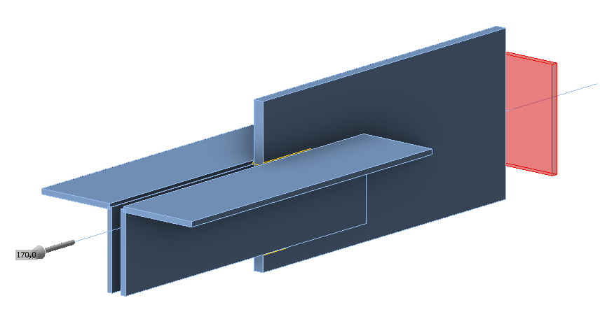
\[ \textsf{\textit{\footnotesize{Fig. 4.2.4 Benchmark example of the welded angle plate joint with parallel fillet welds}}}\]