
10 most important questions about 3D anchoring in Detail
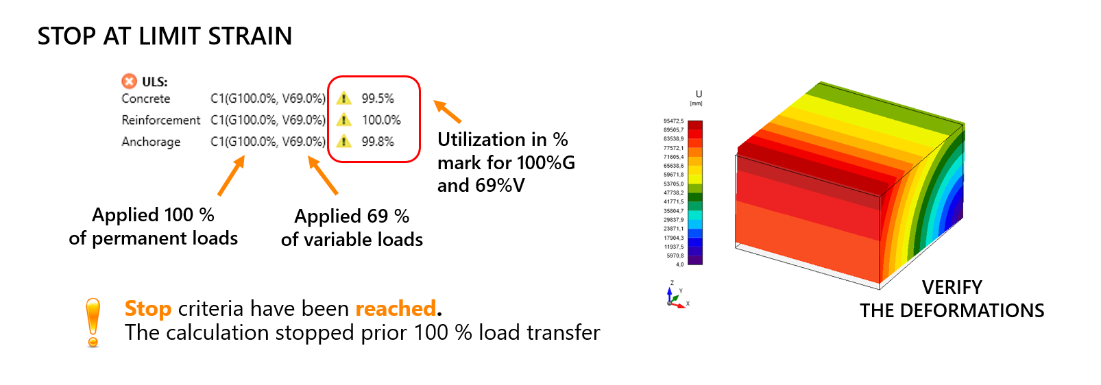
1. Why did the calculation stop early?
The stop criteria in the 3D CSFM model ensure simulations halt at defined limits, see Solution method and load-control algorithm for 3D CSFM in the theoretical background for IDEA StatiCa Detail. By default, the "Stop at Limit Strain" option is active, stopping calculations when some of ULS criteria are reached. Utilization is checked for concrete, reinforcement, and anchorage. Concrete strain is limited to 5 % in compression and 7 % in tension due to convergence needs. Rebar plastic strain is capped at 5 %, while anchorage uses slip-based limits, not bond stress. This could be caused by several reasons. The most common reason is missing reinforcement. Divergence errors may also arise from an improperly supported model, leading to excessive deformation. Another reason can be that the design is not satisfying for the specified load and is simply overloaded.
2. What types of supports can be used in Detail?
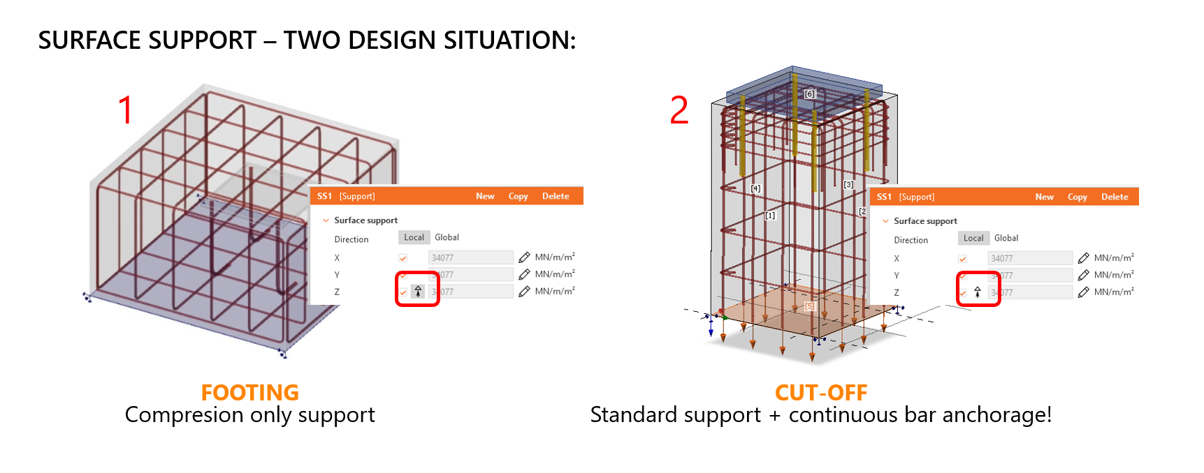
In 3D detailing, surface supports can add stiffness in all directions. By default, supports are compression-only (gray button), which can cause structures to "fly away" due to a lack of tension resistance. To allow tension, toggle the button to white. There are two different suggested approaches:
1) Use default compression-only support for footings resting on ground, but remember to manually apply self-weight, as it's not exported from IDEA StatiCa Connection.
2) For submodels (e.g., balconies, pedestals...) with continuous rebars, use standard support and continuous bar anchorage. This adds single-point constraints, ensuring proper force transfer and avoiding errors like concrete cover peeling or model divergence. Without it, models may fail due to strain limits (e.g., 7 % in tension).
For detailed information about the functionalities of Detail 3D, see Full functionalities of Detail 3D.
3. Why is it so important to follow the detailing rules?
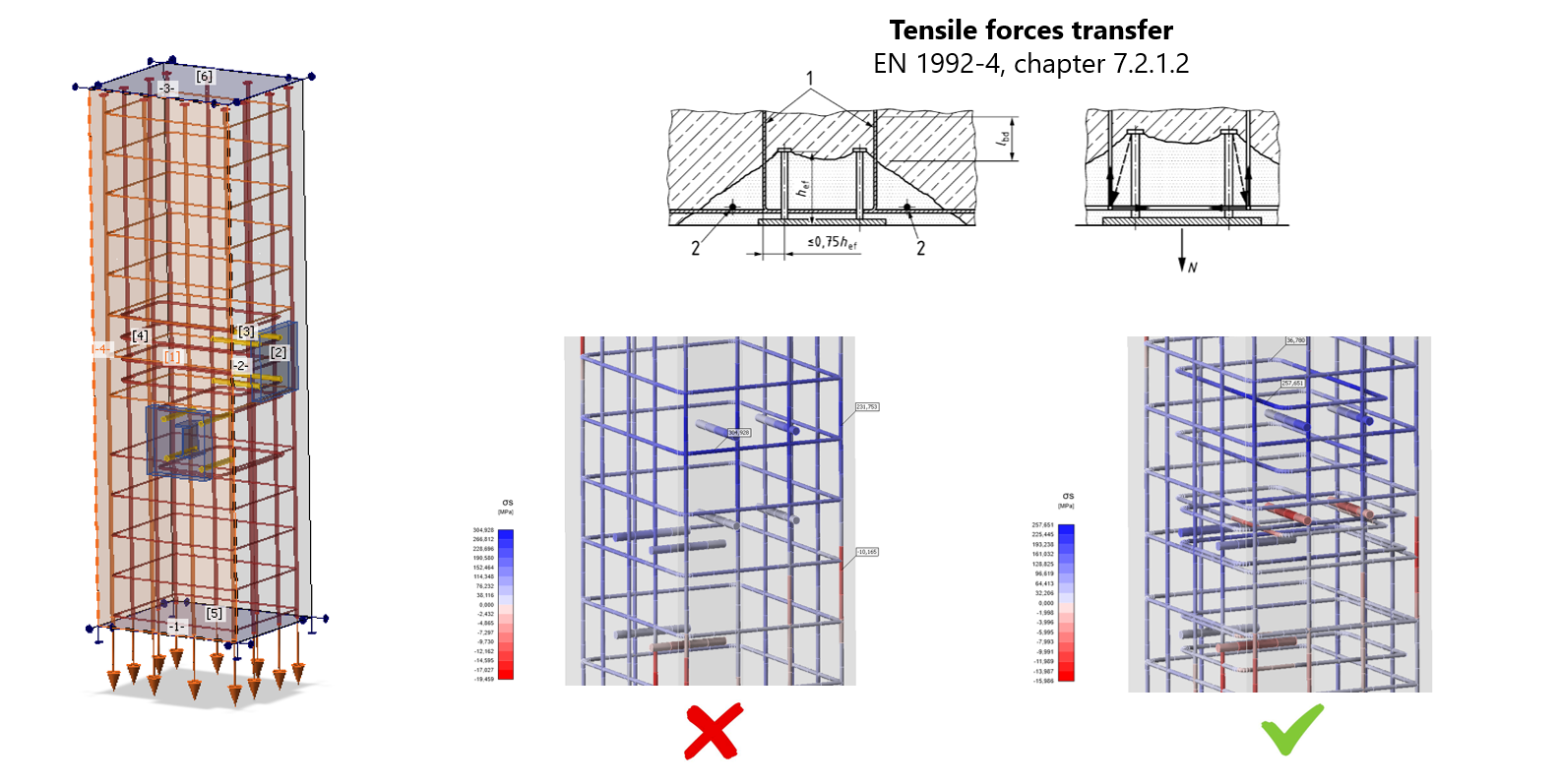
The designed reinforcement should follow code-based detailing rules (e.g., supplementary reinforcement for tensile and shear force transfer according to EN 1992-4). Detail 3D ensures proper force flow: compression zones in concrete and tension in rebars. Proper reinforcement is essential as concrete doesn’t transfer tension. Detailing rules are not automated—users must apply them manually, and it is the structural engineer's responsibility to reinforce the concrete block in the correct way.
4. How do I model shear force transfer correctly?
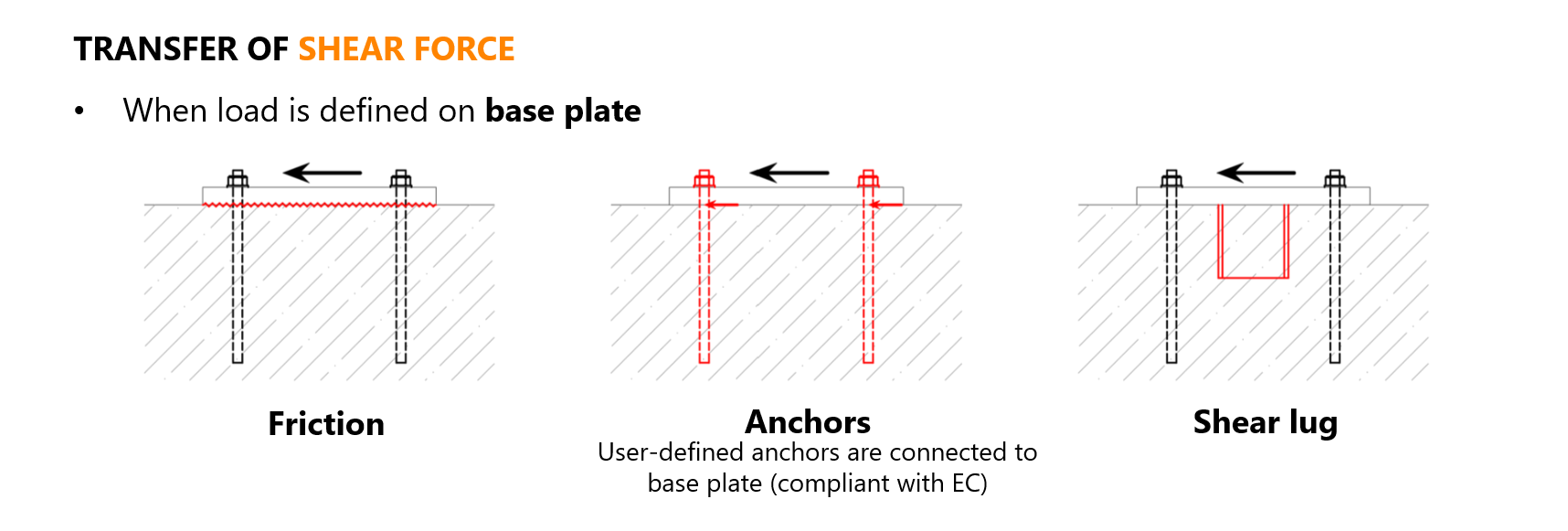
Shear force in base plates can be transferred via friction, anchors, or shear lugs, but only one method can be used at a time. For friction, ensure correct load case sequencing: apply compression (permanent) first, then shear (variable). If done incorrectly, the base plate may "fly away."
With a proper loading sequence and the friction coefficient set to 0.25, shear force can be transferred for 25% of the compression force. For shear-lugs, full shear force is transferred through them, but they aren't checked in IDEA StatiCa Detail. First, check the shear lugs in IDEA StatiCa Connection, then import into Detail. Load transfer in concrete blocks follows typical stress paths (flanges/web) based on load direction. For anchors, the user can define which anchors are effective for shear transfer. Still, they also aren't checked for shear in Detail—so verify their capacity first in Connection before simulating in Detail.
5. What to consider when exporting from Connection to Detail?
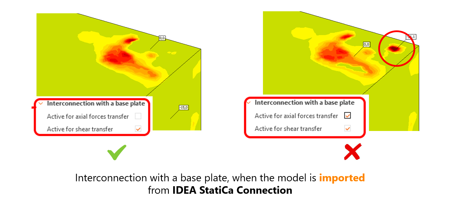
The loads can be applied directly to anchors (tension, compression, shear) or the base plate (all six internal forces). Anchors and base plates are modeled as separate elements, so the force transfer between them must be manually activated through constraints.
- When exporting the anchoring model from IDEA StatiCa Connection (e.g., see BIM link Connection to Detail - Eccentrically loaded anchoring), axial force transfer between anchors and the base plate is turned off to avoid unwanted additional prying of the base plate.
- Alternatively, when modelling from scratch and applying load directly on the base plate, the user has to activate axial and shear transfer between the base plate and anchors.
6. What stiffness of the base plate should be set?
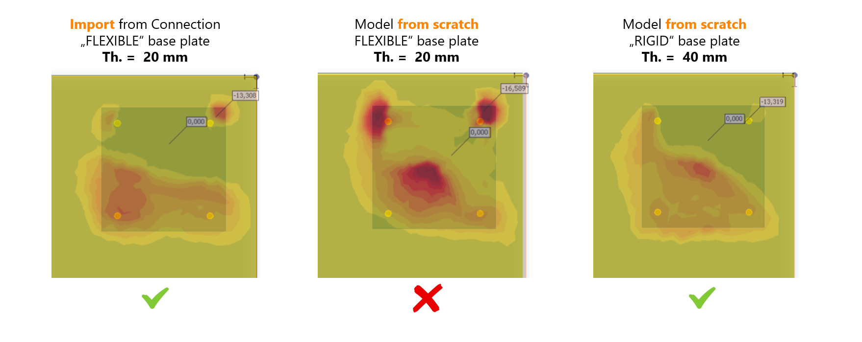
Setting the correct stiffness of the base plate is also important. Three models are compared in the following figure:
- a flexible base plate exported from Connection,
- a flexible base plate modeled directly in Detail 3D with a load applied at a single point,
- and a rigid base plate with increased thickness, with a load applied at a single point.
Results showed that flexible plates modeled directly in Detail 3D produce inaccurate stress distributions and artificial prying effects. The rigid plate eliminates these issues, giving results consistent with the Connection export. Anchor forces were similar in the first and the third models, but the second (flexible plate in Detail 3D) overestimated anchor forces by over 30 %, making it an incorrect approach. Therefore, if not exporting from Connection, and loading at a single point, to get the interaction between the base plate and concrete as close to reality as possible, the suggestion is to use the stiff base plate.
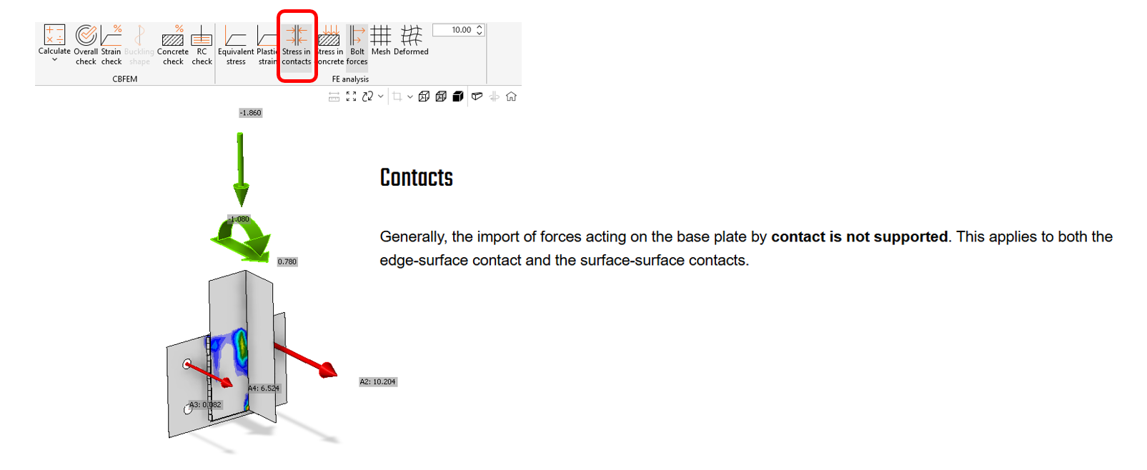
7. What about the contact stress?
In Connection, setting a Contact between two plates and displaying the contact stress is possible. However, it is a known limitation (see Known Limitation for Detail 3D) of the anchoring export from the Connection to Detail that this contact stress is not imported. The consequence of missing effects caused by contact stress is that the imported forces are not in equilibrium on the base plate, and the calculation could not be performed because of the huge base plate deformation and model divergence.
How to resolve this limitation?
- way 1 - do not use Contact in the Connection model (Contact is justifiable in a narrow range of use cases)
- way 2 - to model the anchoring directly in the Detail with the rigid base plate (see question 6)
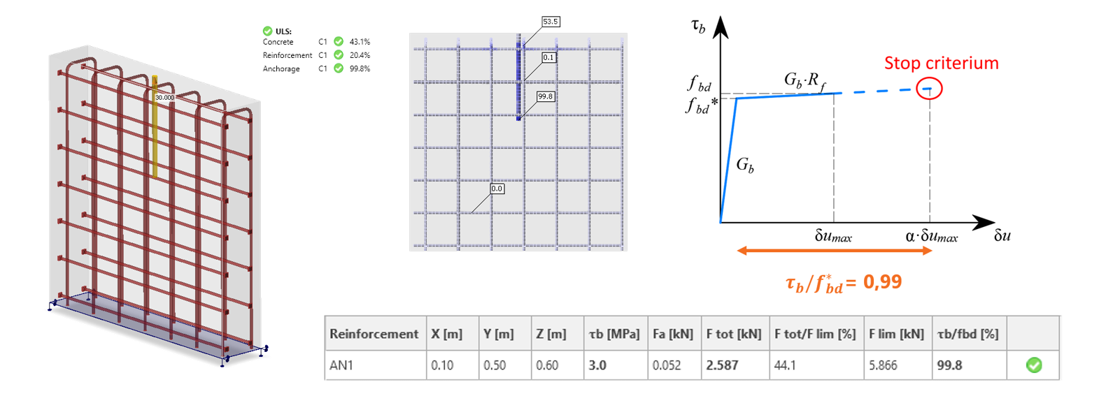
8. Why does bond stress exceed 99,9 % so fast?
In most models, bond stress in anchorage exceeds 99,9% utilization for very low tension load levels. The reason can be found in the bond stress-strain diagram between the anchor/reinforcement and the concrete, as shown in the figure below. The bond reaches its ultimate stress rapidly, and any further loading leads to plastic deformation of the bond. To determine the ultimate bond stress for the adhesive anchors, see the article Bond strength for anchors in Detail 3D.
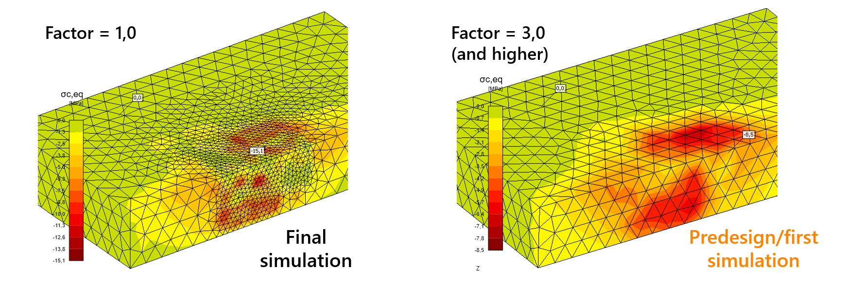
9. How should I manage mesh settings?
Mesh quality is crucial for 3D simulations, especially for nonlinear problems, as it directly impacts calculation time. The mesh multiplier ranges from 0.5 to 5, with 1 being the default. Using a factor of 5 speeds up simulations, helping identify errors, but results may be inaccurate (over 30% error). After verifying the model, the suggested factor is 1 or lower for accurate stress and strain, which increases analysis time. A coarse mesh (higher factor) is used for predesign, while a finer mesh (lower factor) provides more accurate results in the final simulation, especially around anchors.
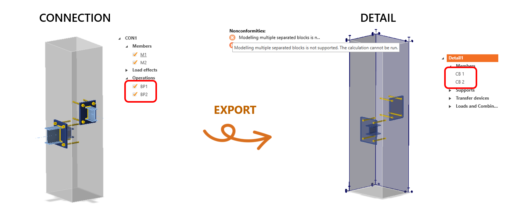
10. Is it possible to import multiple anchorings?
Yes, it is. And what happens after exporting the multiple anchoring from Connection to Detail? Two or more concrete blocks are imported to Detail depending on the number of base plates in the Connection, where every base plate has its own concrete blocks. The known limitation (see Known Limitation for Detail 3D) is that multiple solid blocks are not supported in Detail. So the user has to delete all blocks besides one, and relate all the other base plates to that block. Then, the correct anchor and weld forces distribution is reached.
Conclusion
The 3D CSFM in IDEA StatiCa Detail is a powerful tool for modeling nonlinear concrete and rebar behavior, ensuring compliance with Eurocode and ACI. It effectively handles bond interactions, tension and compression zones, and reinforcement layouts, offering robust anchoring and load transfer solutions. The criteria ensure that calculations stop when critical strain limits are reached, and proper reinforcement detailing is essential for realistic results. Mesh quality is crucial for accurate simulations, with finer meshes providing better precision at the cost of longer analysis times. Supplementary reinforcement, shear force transfer, and correct export settings are also key factors in achieving accurate, code-compliant designs.
For more detailed information, take a look at the webinar 10 Most Frequently Asked Questions for 3D Anchoring.