SCIA Engineer collegamento BIM per la progettazione strutturale in calcestruzzo (EN)
1 Come attivare il collegamento
- Scarica e installa (come amministratore) l'ultima versione di IDEA StatiCa
- Assicurati di utilizzare la versione supportata di SCIA Engineer
IDEA StatiCa integra automaticamente il collegamento BIM nel tuo software CAD/CAE durante l'installazione. Puoi verificare lo stato e attivare ulteriori collegamenti BIM per software installati successivamente tramite il programma di installazione del collegamento BIM.
Apri IDEA StatiCa e naviga nel pannello BIM e apri il programma di installazione del collegamento BIM. Potrebbe apparire una notifica "Esegui come amministratore"; conferma con il pulsante Sì.
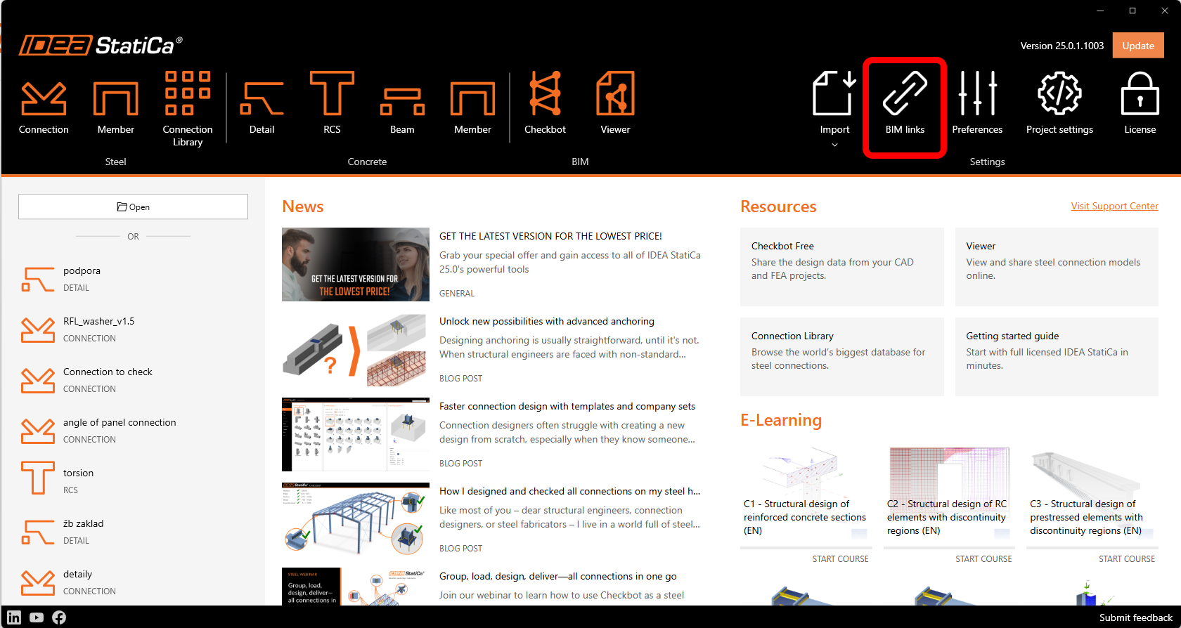
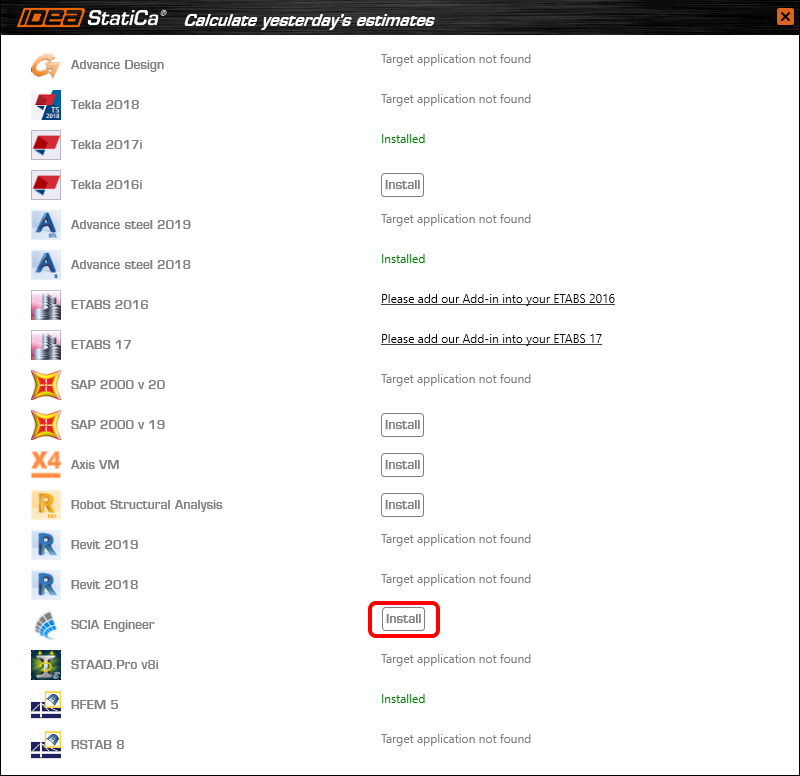
Seleziona il software in cui integrare il collegamento BIM di IDEA StatiCa, fai clic sul pulsante Installa e verifica lo stato di installazione.
Prima di importare il primo esempio, è necessario installare i modelli in Scia Engineer. Per farlo, è necessario eseguire TemplatesInstaller.exe, che si trova solitamente nella cartella di installazione predefinita di IDEA StatiCa (c:\Program Files\IDEAStatiCa\StatiCaX\Templates). Non è necessario ripetere questa operazione se non si cambia la versione di SCIA Engineer.

Seleziona la versione di SCIA Engineer in cui verranno installati i modelli.
Nota: Nella versione appena rilasciata SCIA Engineer 26, si riscontra un problema con la generazione del file XML che causa il crash di SCIA. Si consiglia di utilizzare SCIA Engineer 25 o versioni precedenti per questo collegamento BIM fino alla risoluzione del problema.

Dopo Copia, sei pronto per l'esportazione del modello.
2 Esportazione
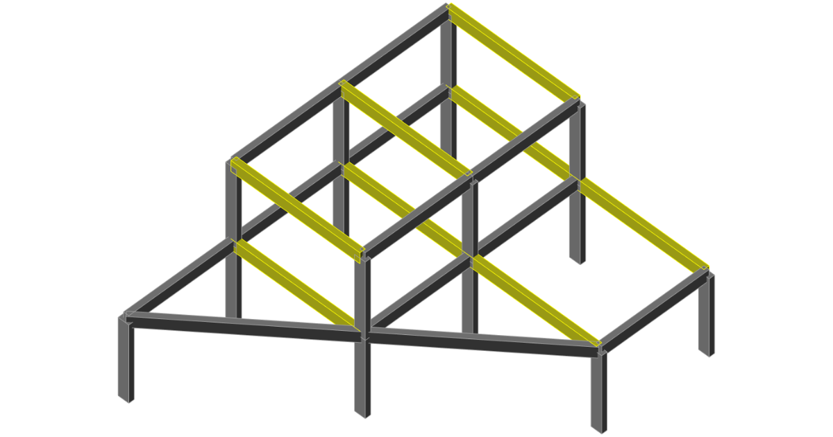
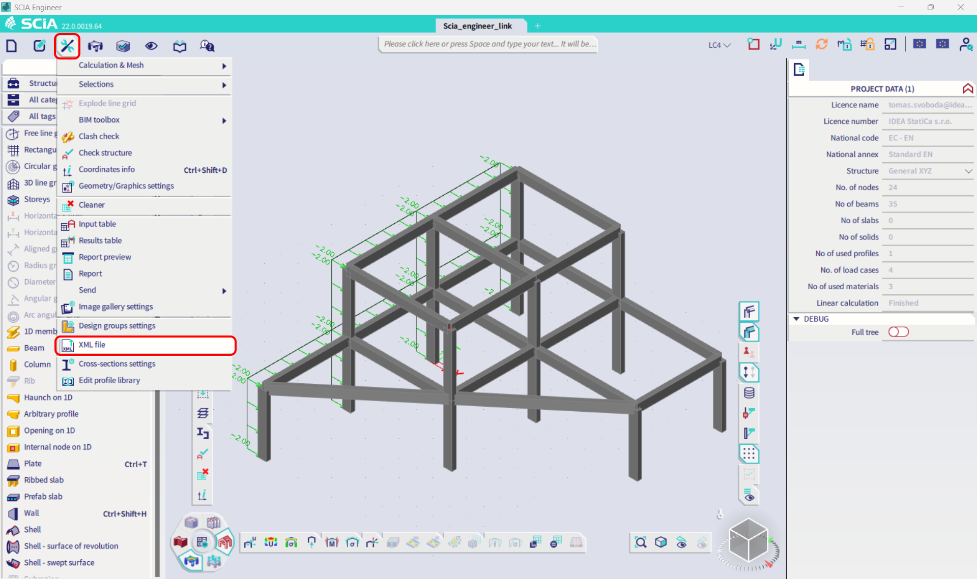
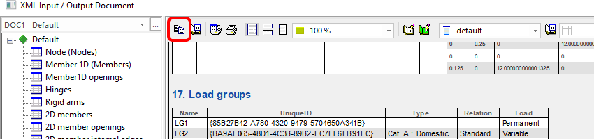
Apri il modello Scia_engineer_link.esa dai file sorgente scaricati, esegui l'analisi lineare per ottenere i risultati e nel menu Strumenti seleziona File XML.
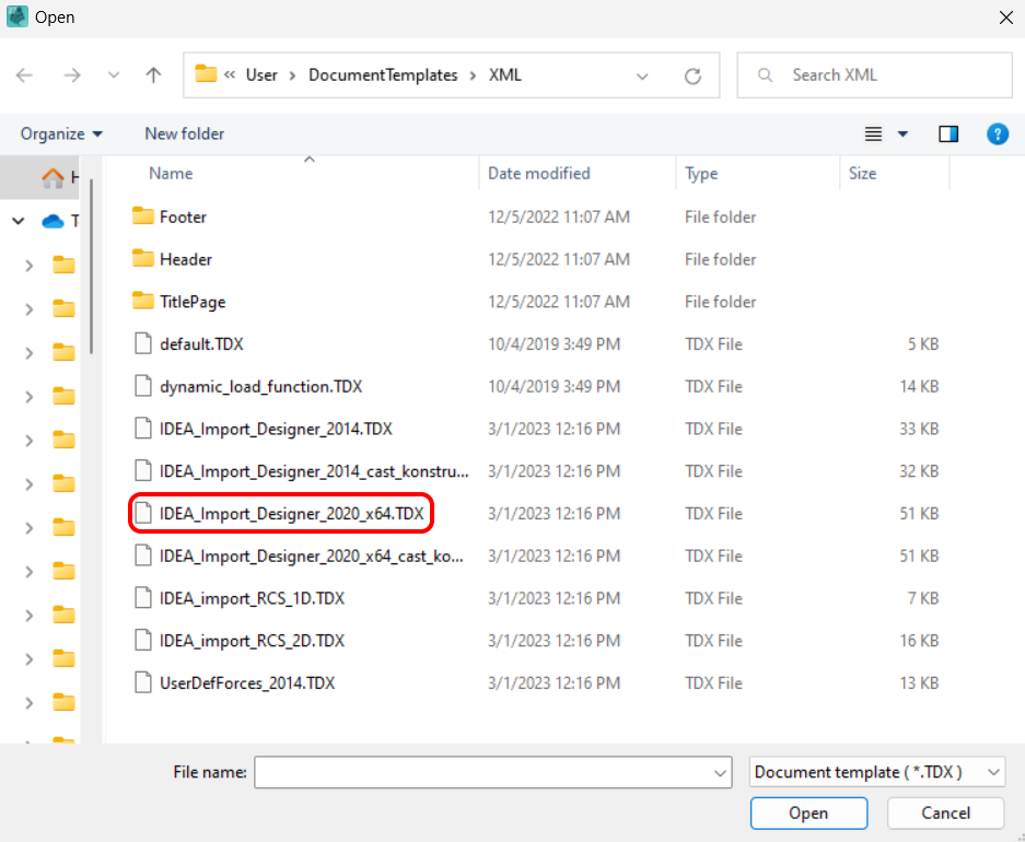
Crea un nuovo documento XML di Input/Output e carica uno dei modelli installati.

In questo esempio esporti l'intera struttura, quindi seleziona il modello predefinito evidenziato.

Nella finestra di dialogo successiva, imposta il percorso desiderato per i file XML e XML.DEF. È sempre importante mantenere entrambi i file nella stessa cartella e con lo stesso nome (entrambi contengono i dati necessari per un'importazione corretta). Se la cartella predefinita è una posizione in Programmi, è necessario scegliere una posizione diversa (ad es. C:\Work), poiché i file in Programmi non possono essere sovrascritti e il caricamento del file XML fallirebbe.

3 Importazione
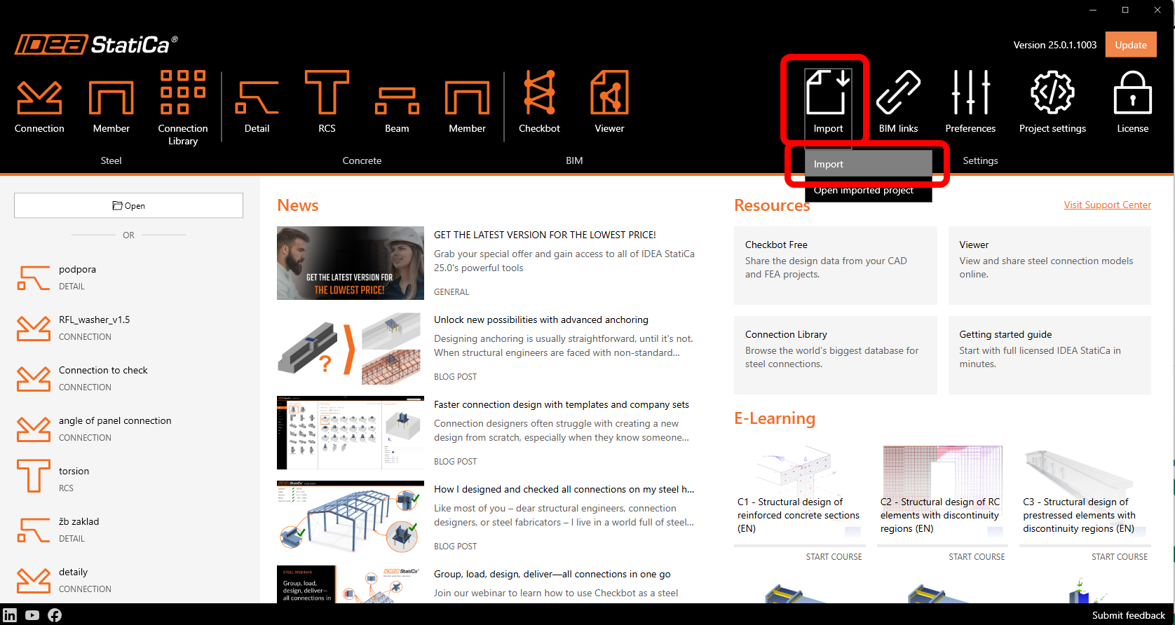
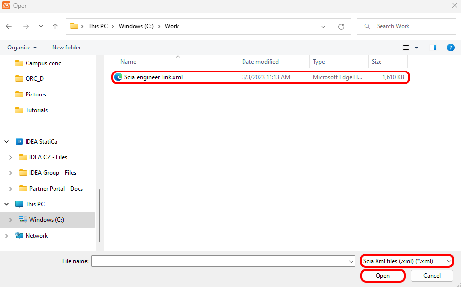
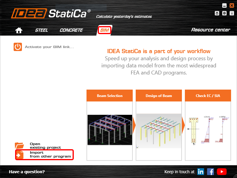
Apri IDEA StatiCa e naviga nel pannello BIM e fai clic su SCIA Engineer. Seleziona il file XML esportato.
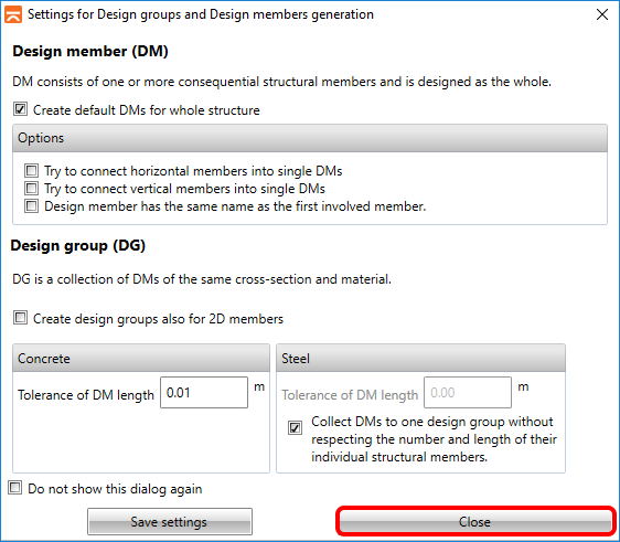
Se importi per la prima volta, è necessario impostare la generazione dei gruppi di progetto e degli elementi.
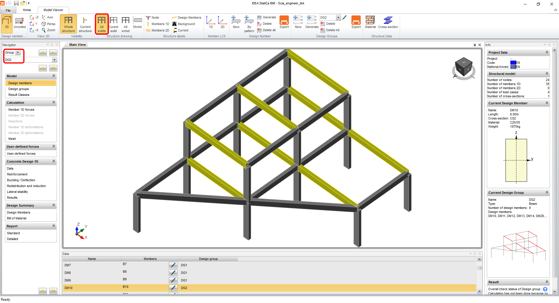
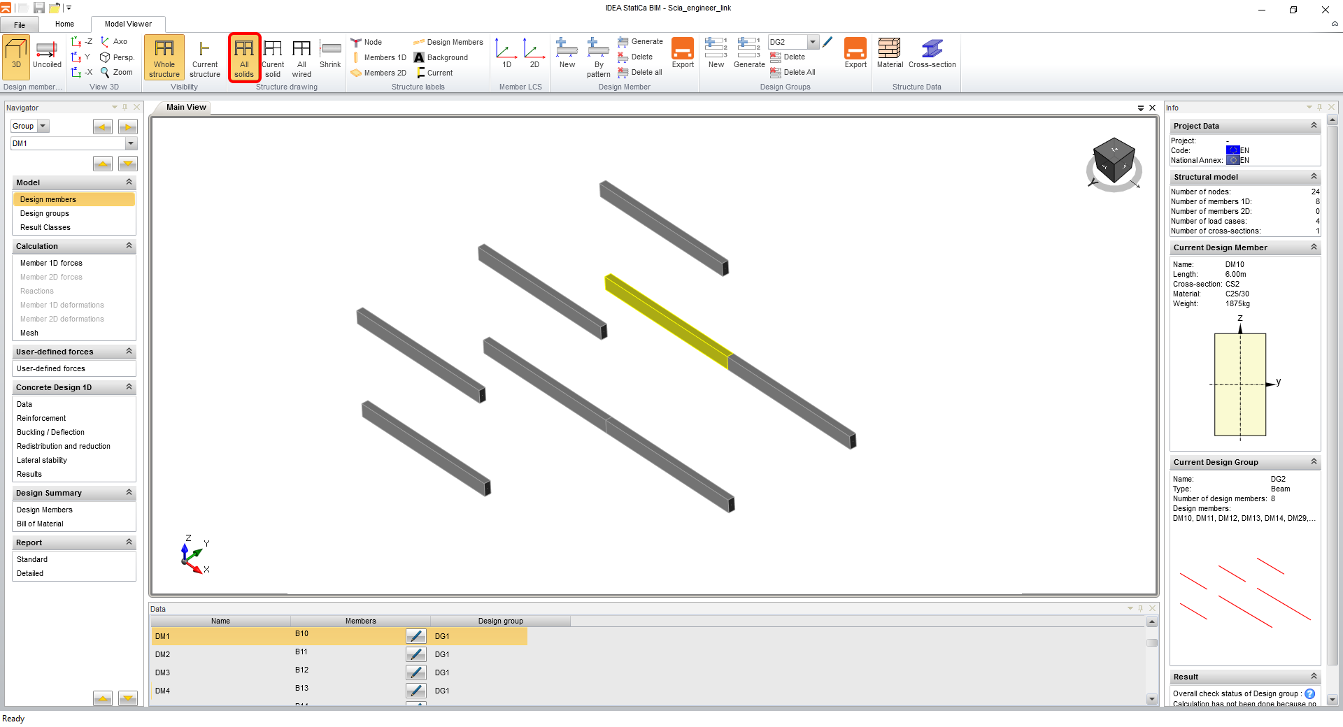
Il modello importato appare come nell'immagine seguente. Per una visualizzazione migliore, puoi attivare il rendering di tutti gli elementi come Tutti i solidi. Passa anche ai gruppi di progetto e seleziona DG2 per verificare contemporaneamente tutte le travi, evidenziate nella finestra principale.
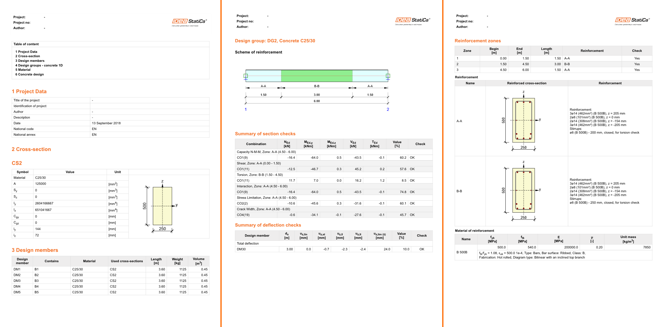
4 Progettazione
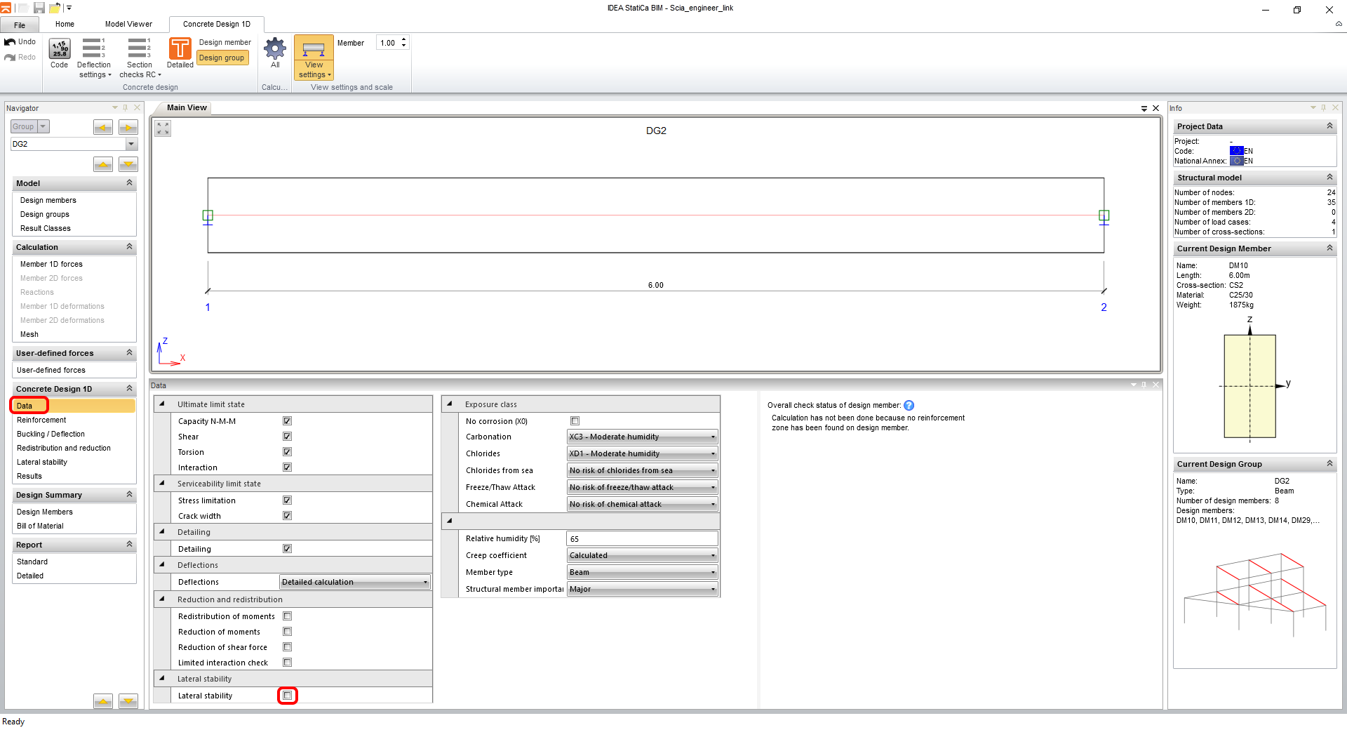
Vai alla scheda Dati nel navigatore per impostare tutti i tipi di verifiche richiesti e le classi di esposizione. Questo tipo di esempio non richiede la verifica della Stabilità laterale.
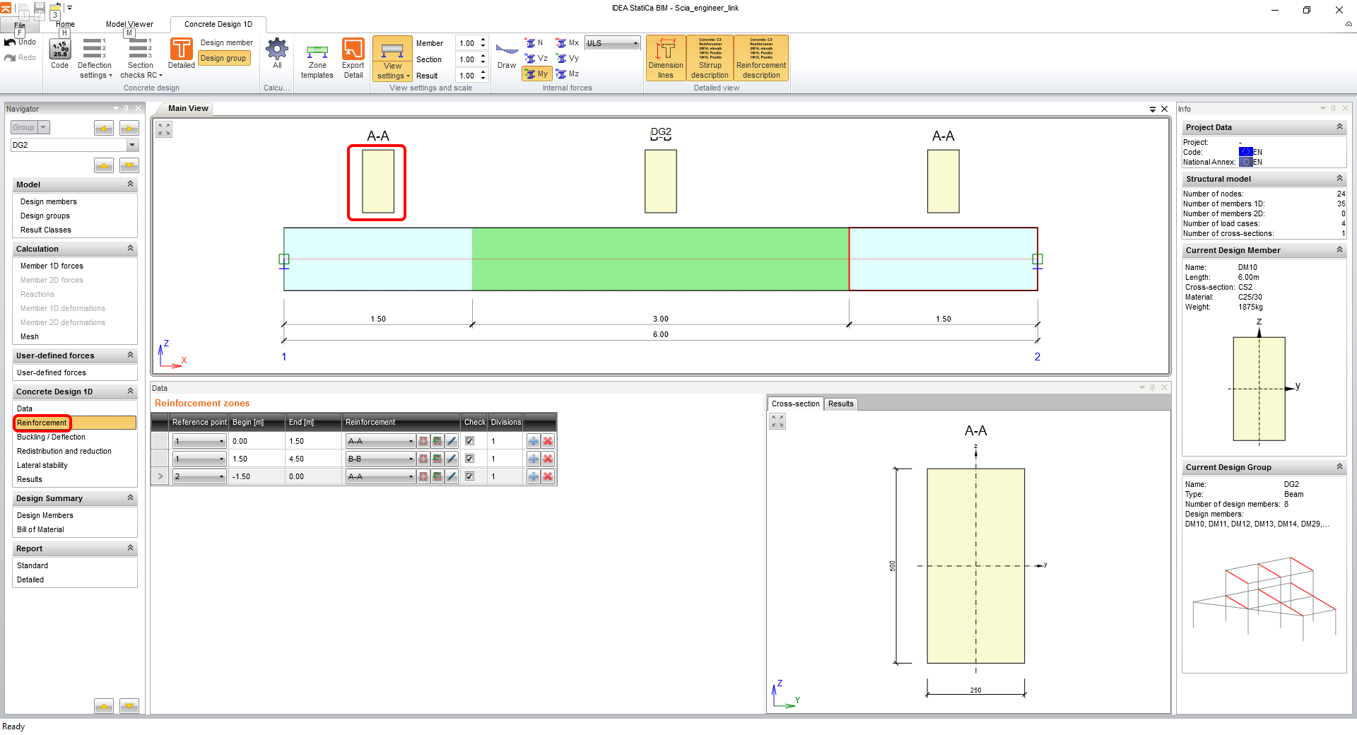
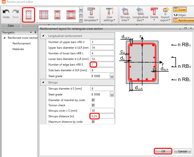
Il passo successivo è inserire l'armatura. Per semplicità in questo tutorial, utilizzerai zone di armatura generate automaticamente. Facendo clic sulla forma della sezione trasversale della zona A-A si apre l'editor dell'armatura.
Utilizzerai il modello per sezioni trasversali rettangolari, inserisci i parametri e concludi facendo clic su OK.
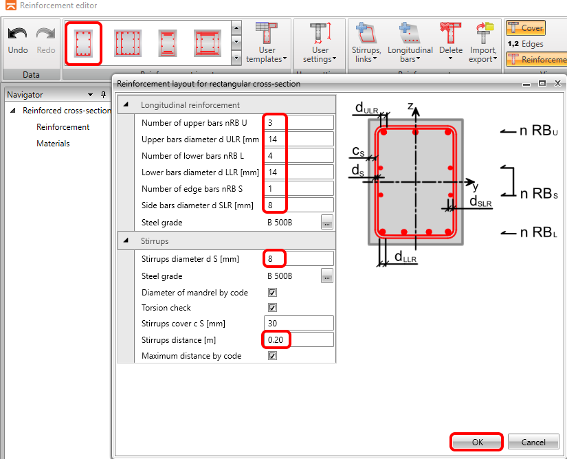
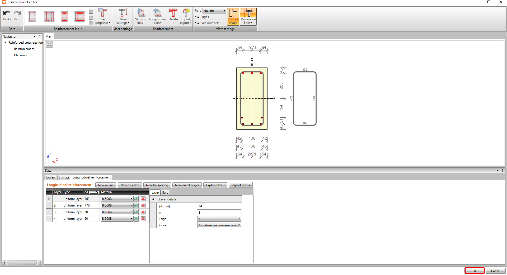
L'armatura viene mostrata nella scena in base ai parametri (si noti che il software ha distribuito automaticamente l'armatura su due strati in conformità alle regole di dettaglio) e puoi tornare all'applicazione Beam facendo clic su OK.

Continua con l'armatura della zona B-B, facendo nuovamente clic sulla forma della sezione trasversale.
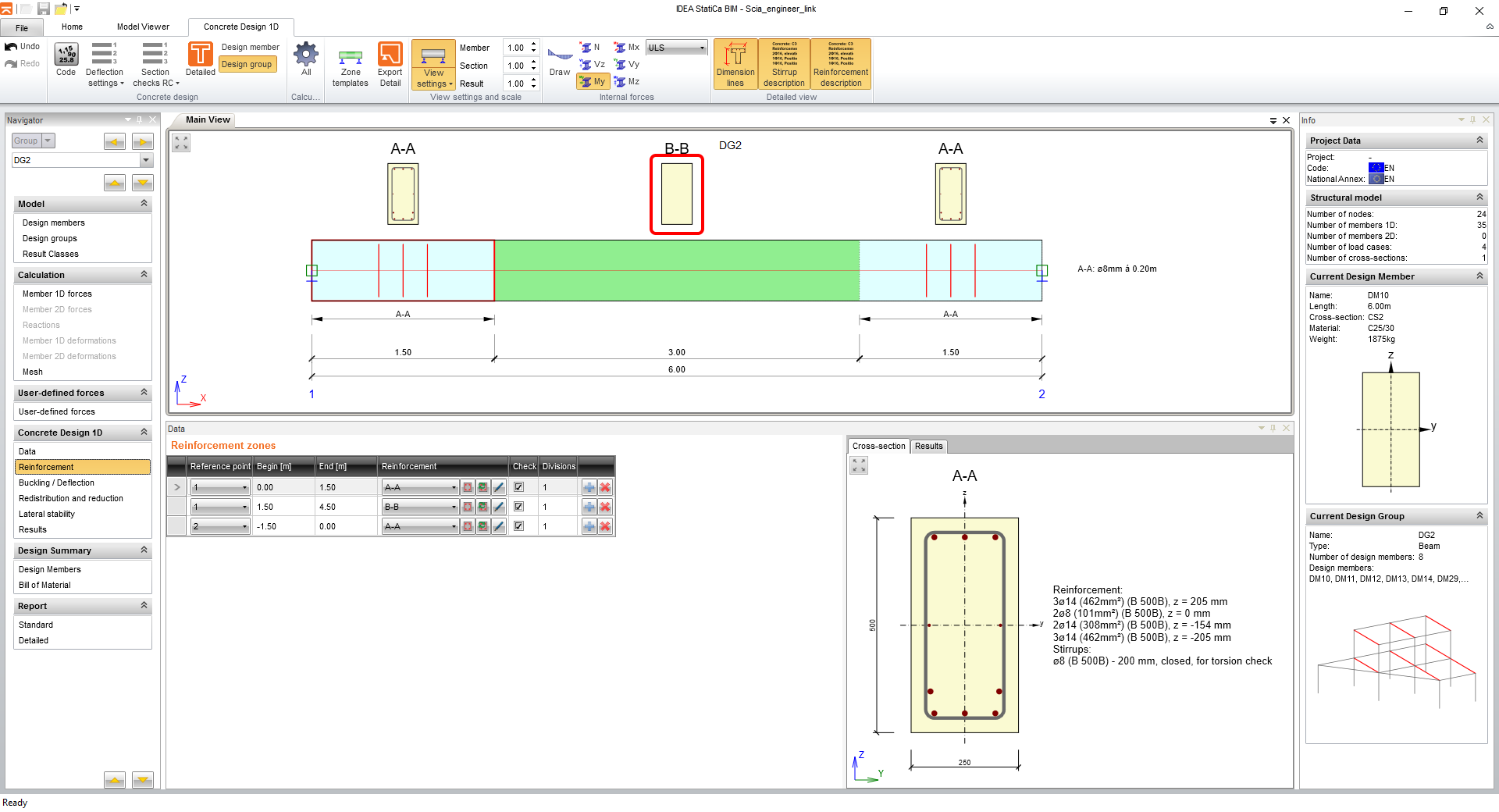
Ripeti i passaggi per il modello di armatura.
I passaggi si concludono con il pulsante OK.
5 Verifica
Fai clic sulla scheda Risultati e i calcoli vengono eseguiti automaticamente.
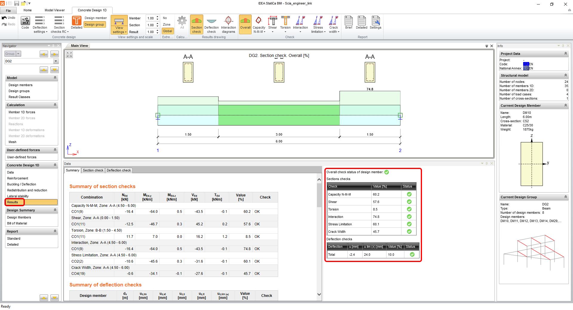
Sul lato destro dello schermo puoi vedere che la tabella di riepilogo mostra tutte le verifiche come soddisfatte. Puoi sempre selezionare il tipo di verifica da visualizzare nella scena tramite le icone della barra multifunzione.
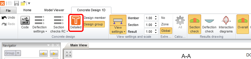
Per visualizzare i risultati dettagliati, puoi esportare le sezioni nel modulo RCS tramite Dettagliato.
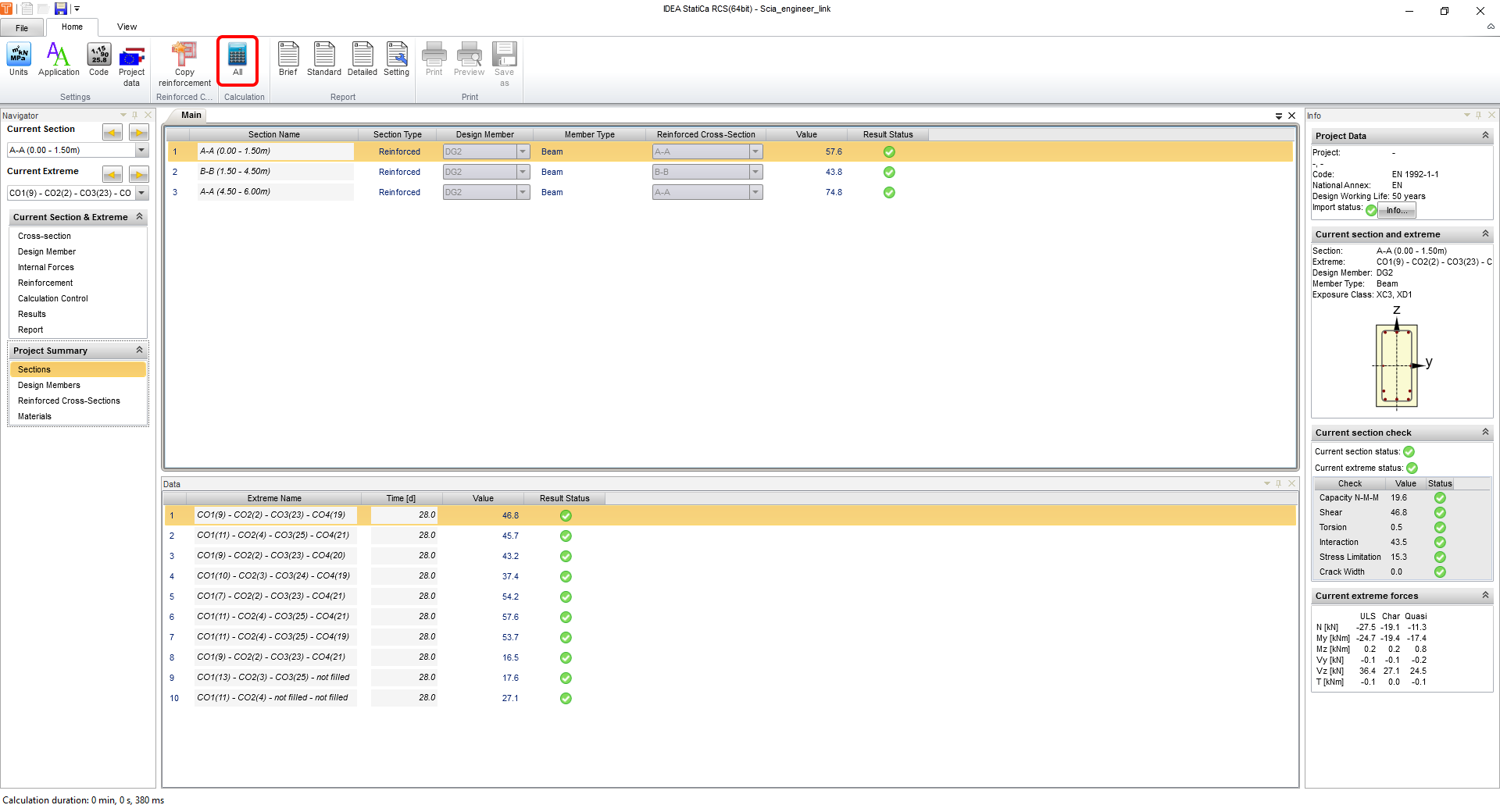
Dopo l'esportazione, l'RCS viene aperto nella scheda Sezioni, dove si esegue il calcolo tramite Tutto.
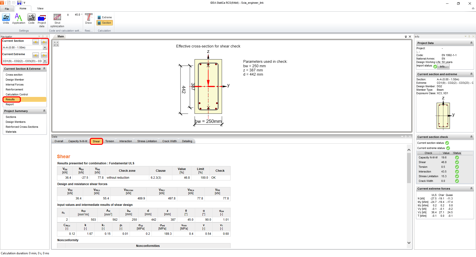
Quando si passa alla scheda Risultati, è possibile esaminare tutte le verifiche e i risultati dettagliati anche in forma grafica, insieme a tutti i parametri di input/output. A sinistra, nel navigatore, è possibile passare tra sezioni ed estremi per i quali si visualizzano i risultati. Lo screenshot mostra i risultati della prima zona di armatura A-A e i risultati della verifica a Taglio.
Per chiudere questa visualizzazione dei risultati in RCS e tornare a IDEA BIM, fai clic sul pulsante con la croce nell'angolo in alto a destra.
6 Relazione
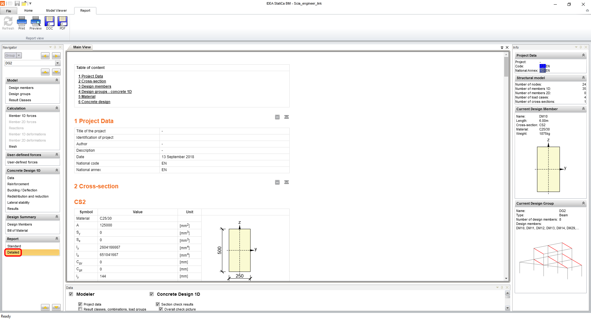
Infine, vai alla scheda Dettagliato nella sezione Relazione nel navigatore. IDEA StatiCa offre una relazione completamente personalizzabile da stampare o salvare in formato modificabile.
7 Esportazione di una parte del modello (opzionale)
Per esportare solo una parte del modello Scia Engineer, è necessario utilizzare un modello denominato IDEA_Import_Designer_2020_cast_konstrukce.TDX.

Selezionalo dall'elenco.

Seleziona gli elementi desiderati per l'esportazione nell'albero delle entità XML.

La stessa selezione viene effettuata per le forze interne da esportare.

Come in tutti i modelli, fai clic su Esporta.
Imposta il percorso per i file esportati e il loro nome.

Apri IDEA StatiCa e naviga nel pannello BIM e fai clic su Scia Engineer. Seleziona il file XML esportato.
Se importi per la prima volta, è necessario impostare la generazione dei gruppi di progetto e degli elementi.

Il modello importato appare come nell'immagine seguente.
Puoi continuare con esattamente gli stessi passaggi della sezione 4 Progettazione.
8 Spiegazione dei modelli TDX alternativi
Il pacchetto installato contiene diversi modelli che possono essere utilizzati per diversi tipi di lavori, anche se il processo di esportazione è lo stesso. Questo capitolo ne riassume l'utilizzo.

• IDEA_Import_Designer_2020.TDX
• IDEA_Import_Designer_2020_cast_konstrukce.TDX
• IDEA_import_RCS_1D.TDX
• IDEA_import_RCS_2D.TDX
• UserDefForces_2014.TDX
IDEA_Import_Designer_2020.TDX è il modello predefinito per l'esportazione dell'intero modello in Scia Engineer ed è descritto in dettaglio nei primi capitoli di questo tutorial.
IDEA_Import_Designer_2020_cast_konstrukce.TDX è un modello per l'esportazione di parti del modello in Scia Engineer ed è descritto in dettaglio nel capitolo 7 di questo tutorial.
IDEA_import_RCS_1D.TDX è un modello per l'esportazione di una sezione di elementi 1D per verifiche dirette nell'applicazione RCS.
IDEA_import_RCS_2D.TDX è un modello per l'esportazione degli estremi su elementi 2D selezionati o degli estremi globali di tutti gli elementi 2D selezionati per verifiche dirette nell'applicazione RCS.
UserDefForces_2014.TDX è un modello per l'esportazione dei soli risultati delle forze interne (ad es. carico mobile). L'utilizzo di questo modello è illustrato nel tutorial per BLR nell'applicazione Beam.