Il diagramma N-M-κ mostra la curvatura (rigidezza flessionale) di un elemento in funzione del momento flettente applicato e della forza normale. Esistono tre tipi di diagrammi N-M-κ:
- a breve termine,
- a lungo termine
- SLU.
Questi diagrammi differiscono per i tipi di diagrammi tensione-deformazione utilizzati nel calcolo (spiegati di seguito).
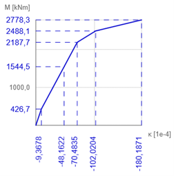
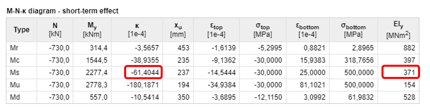
Il calcolo della rigidezza per stati caratteristici selezionati della sezione trasversale viene utilizzato per determinare il diagramma N-M-κ. In generale, può essere qualsiasi stato della sezione trasversale dal quale viene calcolata la risposta e dal quale vengono derivate la rigidezza flessionale e la curvatura. In IDEA RCS si considerano quattro punti caratteristici (Mr, Mc, Ms e Mu)
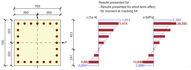
Mr - il momento di fessurazione
La sezione trasversale è soggetta alla forza normale definita dall'utente e il piano delle deformazioni inizia a ruotare (nella direzione del momento flettente specificato) fino a quando la resistenza ultima a trazione del calcestruzzo viene raggiunta in una fibra di calcestruzzo (per la classe di calcestruzzo C30/37 questo è fctm = 2,896 MPa). Per il calcolo viene utilizzato un diagramma tensione-deformazione bilineare con ramo plastico orizzontale sia per l'armatura che per il calcestruzzo.
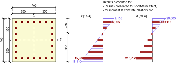
Mc - il momento flettente quando viene raggiunta la resistenza a compressione del calcestruzzo
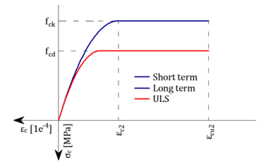
Dal passo precedente viene identificata la fibra di calcestruzzo più sollecitata a compressione. Per questa fibra viene impostata la deformazione alla resistenza ultima del calcestruzzo (fck/Ecm per il breve termine, fck/Eceff per il lungo termine e fcd/Ecm per il diagramma SLU). In base alla forza normale definita e alla direzione del momento flettente, viene avviato il processo iterativo per trovare il piano delle deformazioni al fine di trovare un equilibrio tra la risposta della sezione trasversale e la forza normale definita. Per il calcolo viene utilizzato un diagramma tensione-deformazione bilineare con ramo plastico orizzontale sia per l'armatura che per il calcestruzzo.
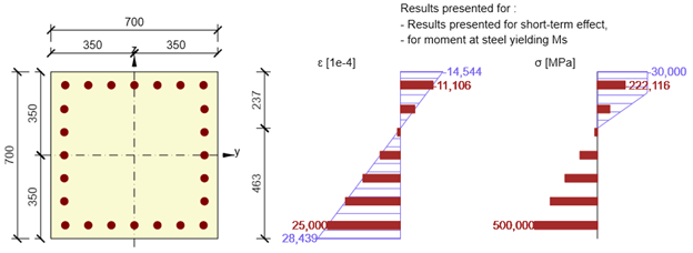
Ms - il momento flettente quando viene raggiunta la tensione di snervamento nella barra di armatura più sollecitata
Un altro punto caratteristico del diagramma N-M-κ è lo stato tensionale della sezione trasversale quando viene raggiunta la tensione di snervamento nella barra di armatura più sollecitata (la deformazione della barra è uguale a fyk/Es per i diagrammi a breve e lungo termine, fyd/Es per il diagramma SLU). Il processo iterativo trova un equilibrio delle forze normali nella sezione trasversale ruotando il piano delle deformazioni attorno al punto specificato dalla posizione della barra di armatura più sollecitata. Per il calcolo viene utilizzato un diagramma tensione-deformazione bilineare con ramo plastico orizzontale sia per l'armatura che per il calcestruzzo.
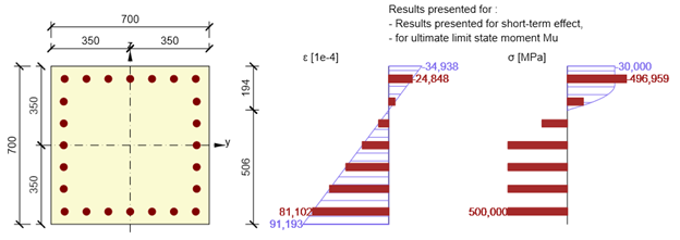
Mu - il momento flettente allo stato limite ultimo
Questa è la capacità portante ultima di una sezione trasversale a flessione, quando la sezione trasversale è soggetta alla forza normale di progetto definita Ned. Per il calcolo della capacità della sezione trasversale si assume che vengano raggiunte la resistenza a compressione nella fibra di calcestruzzo più sollecitata e la resistenza a trazione nella barra di armatura più sollecitata (deformazione massima per il calcestruzzo εcu = 0,1 e per l'armatura εs,max = 0,5). Per il calcolo vengono utilizzati un diagramma tensione-deformazione bilineare con ramo plastico orizzontale per l'armatura e un diagramma parabola-rettangolo per il calcestruzzo.
La rigidezza e la curvatura risultanti dovute alla combinazione di forza normale e momento flettente definita dall'utente (Md) vengono quindi calcolate mediante interpolazione lineare dei singoli punti caratteristici del diagramma N-M-κ.
Calcolo delle rigidezze e delle curvature
Le rigidezze e le curvature per ciascuno stato tensionale della sezione trasversale (Mr, Mc, Ms o Mu) vengono calcolate direttamente dalla rotazione del piano delle deformazioni.
\[E{{A}_{x}}=\frac{N}{{{\varepsilon }_{x}}}\]
EAx . . rigidezza assiale dell'elemento
N . . . . la forza normale specificata
εx . . . deformazione assiale nel baricentro della sezione trasversale in calcestruzzo
\[E{{I}_{y}}=\frac{M}{\kappa }\]
EIy . . . rigidezza flessionale dell'elemento
M . . . il momento flettente calcolato Mr, Mc, Ms o Mu
κ . . . . la curvatura dell'elemento, calcolata come la tangente dell'angolo tra il piano delle deformazioni e l'asse longitudinale dell'elemento
Esempio pratico
Una sezione trasversale in calcestruzzo (classe C30/37) è armata con armatura ϕ32 (classe B500B). La combinazione quasi-permanente definita è N = -730 kN e My = 557 kNm.
Il piano delle deformazioni per il punto caratteristico Ms è determinato da IDEA RCS come segue:
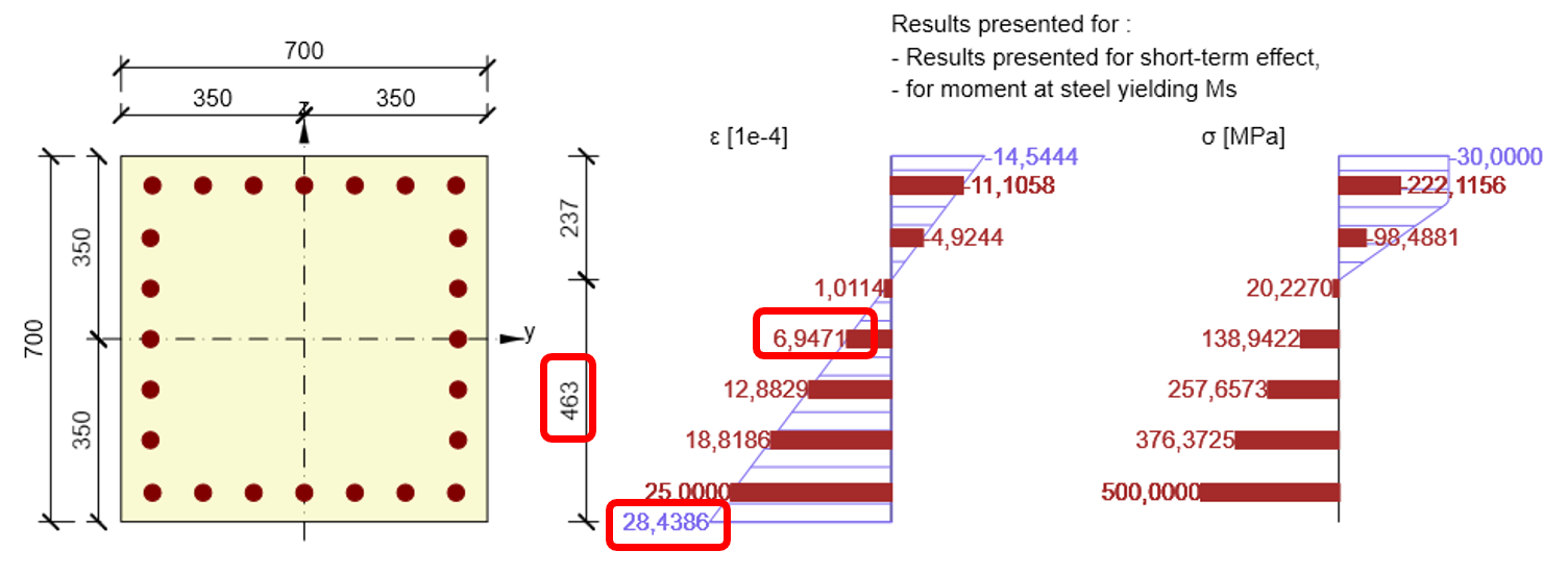
\[E{{A}_{x}}=\frac{N}{{{\varepsilon }_{x}}}=\frac{730}{6,9471\cdot {{10}^{-4}}}=1050,798MN\]
\[\kappa =\frac{28,4386\cdot {{10}^{-4}}}{0,463}=61,422\cdot {{10}^{-4}}{{m}^{-1}}\]
\[E{{I}_{y}}=\frac{{{M}_{s}}}{\kappa }=\frac{2277,4}{61,422\cdot {{10}^{-4}}}=370,776MN{{m}^{2}}\]
Diagrammi tensione-deformazione utilizzati per il calcolo
Armatura - Mr, Mc, Ms e Mu
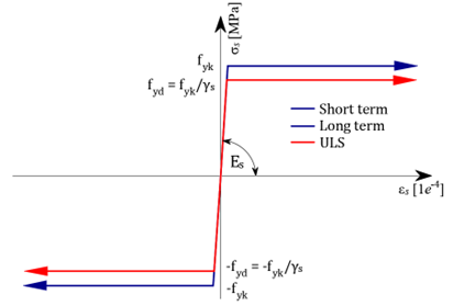
Calcestruzzo - Mr, Mc, Ms
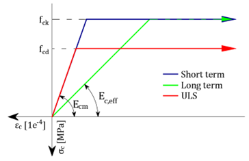
Calcestruzzo - Mu