
1.2 A CSFM főbb feltételezései és korlátai 2D-ben
A CSFM a beton maximális főnyomófeszültségét (σc2r) és a vasalás feszültségeit (σsr) a repedéseknél veszi figyelembe, miközben elhanyagolja a beton húzószilárdságát (σc1r = 0), kivéve annak a vasalásra gyakorolt merevítő hatását. A húzási merevítő hatás figyelembevétele lehetővé teszi a vasalás átlagos alakváltozásainak (εm) szimulálását. Fiktív, forgó, feszültségmentes repedéseket vesznek figyelembe, amelyek csúszás nélkül nyílnak (2a. ábra), és a repedéseknél fennálló egyensúlyt a vasalás átlagos alakváltozásaival együtt szintén figyelembe veszik.
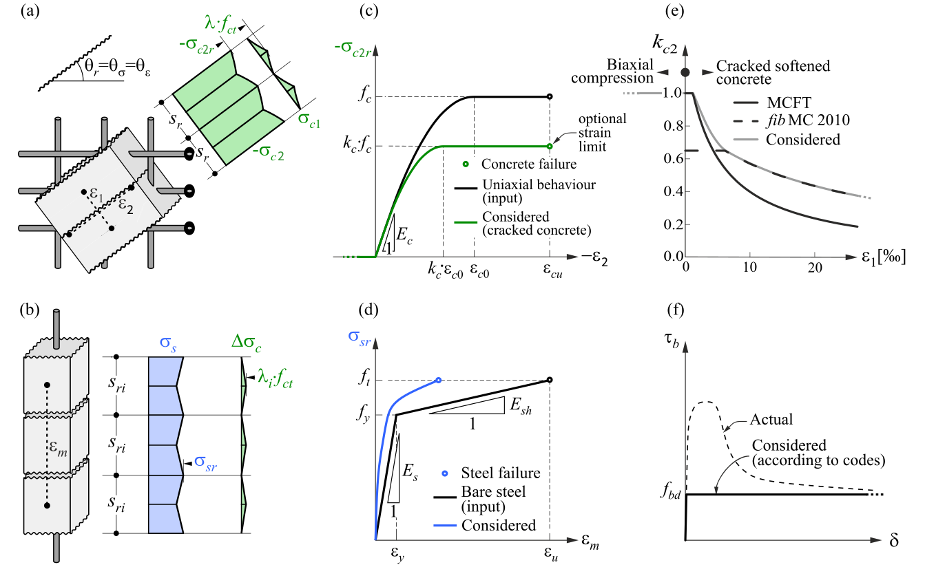
\( \textsf{\textit{\footnotesize{Fig. 2\qquad Basic assumptions of the CSFM: (a) principal stresses in concrete; (b) stresses in the reinforcement direction;}}}\) \( \textsf{\textit{\footnotesize{(c) stress-strain diagram of concrete in terms of maximum stresses with consideration of compression softening;}}}\) \( \textsf{\textit{\footnotesize{(d) stress-strain diagram of reinforcement in terms of stresses at cracks and average strains; (e) compression softening}}}\) \( \textsf{\textit{\footnotesize{law; (f) bond shear stress-slip relationship for anchorage length verifications.}}}\)
Egyszerűségük ellenére hasonló feltételezések bizonyítottan pontos előrejelzéseket adnak síkbeli terhelésnek kitett vasalt szerkezeti elemeknél (Kaufmann 1998; Kaufmann és Marti 1998), feltéve, hogy a biztosított vasalás elkerüli a repedéskor bekövetkező rideg tönkremenetelt. Továbbá a beton húzószilárdságának a végső teherbíráshoz való hozzájárulásának figyelmen kívül hagyása összhangban van a modern tervezési szabványok elveivel, amelyek többnyire a képlékenységi elméleten alapulnak.
Ugyanakkor a CSFM nem alkalmas karcsú elemekre harántirányú vasalás nélkül, mivel az ilyen elemek szempontjából meghatározó mechanizmusokat – mint az aggregátum-összekapaszkodás, a repedéscsúcsnál fennmaradó húzófeszültségek és a csaphatás – amelyek mindegyike közvetlenül vagy közvetve a beton húzószilárdságára támaszkodik, figyelmen kívül hagyja. Bár egyes tervezési szabványok lehetővé teszik az ilyen elemek méretezését félempirikus előírások alapján, a CSFM nem erre a potenciálisan rideg szerkezettípusra készült.
Beton
A CSFM-ben alkalmazott betonmodell a tervezési szabványok által a keresztmetszet-méretezéshez előírt egytengelyű nyomási alkotótörvényeken alapul, amelyek kizárólag a nyomószilárdsától függnek. A CSFM-ben alapértelmezés szerint a parabola-téglalap diagram (2c. ábra) kerül alkalmazásra, de a tervezők egyszerűsített rugalmas–ideálisan képlékeny összefüggést is választhatnak. Az ACI szabvány szerinti ellenőrzésnél kizárólag a parabola-téglalap feszültség-alakváltozás diagram használható. Amint korábban említettük, a húzószilárdságot elhanyagolják, ahogyan az a klasszikus vasbeton-tervezésben is szokásos.
A repedezett betonra vonatkozó hatékony nyomószilárdságot automatikusan értékelik a főhúzó alakváltozás (ε1) alapján a kc2 redukciós tényező segítségével, ahogyan azt a 2c. és 2e. ábra mutatja. Az alkalmazott redukciós összefüggés (2e. ábra) a fib Model Code 2010 nyírási ellenőrzésekre vonatkozó javaslatának általánosítása, amely 0,65-ös határértéket tartalmaz a hatékony betonszilárdság és a beton nyomószilárdsága maximális arányára vonatkozóan, ami más teherbírási esetekre nem alkalmazható.
Az IDEA StatiCa Detail CSFM-je nem alkalmaz explicit tönkremeneteli kritériumot a nyomott beton alakváltozásaira vonatkozóan (azaz a csúcsfeszültség elérése után végtelen képlékeny ágat feltételez). Ez az egyszerűsítés nem teszi lehetővé a nyomásban tönkremenő szerkezetek alakváltozási kapacitásának ellenőrzését. Ugyanakkor a végső teherbírásuk megfelelően becsülhető, ha a repedezett beton tényezőjén (kc2) túl (2e. ábra), a beton ridegségének szilárdság növekedésével arányos növekedését is figyelembe veszik a fib Model Code 2010-ben az alábbiak szerint definiált \( \eta_{fc} \) redukciós tényező segítségével:
\[f_{c,red} = k_c \cdot f_{c} = \eta _{fc} \cdot k_{c2} \cdot f_{c}\]
\[{\eta _{fc}} = {\left( {\frac{{30}}{{{f_{c}}}}} \right)^{\frac{1}{3}}} \le 1\]
ahol:
kc a nyomószilárdság globális redukciós tényezője
kc2 a harántirányú repedések jelenlétéből adódó redukciós tényező
fc a beton hengeres karakterisztikus szilárdsága (MPa-ban az \( \eta_{fc} \) definíciójához).
A számítás stabilitása miatt a kc2 tényező szintén csökkentésre kerül. Ez a csökkentés nem befolyásolja a szerkezeti elemek teljes teherbírását. Az fcd értéket a beton terhelt szilárdságaként (méretezési érték) feltételezve, a kc2 értéke az alábbi szabályok szerint csökken.
σc2r < 0.11fcd kc2=1.0
0.11fcd < σc2r < 0.37fcd kc2 lineáris interpoláció 1,0 és a 2f. ábrán látható
grafikonból vett érték között
σc2r > 0.37fcd kc2 közvetlenül a 2f. ábra grafikonjából kerül leolvasásra
Vasalás
A tervezési szabványok által jellemzően meghatározott idealizált bilineáris feszültség-alakváltozás diagramot alkalmazzák a szabad vasalórudakra (2d. ábra). E diagram meghatározásához csupán a vasalás alapvető tulajdonságainak ismerete szükséges a tervezési fázisban (szilárdság és képlékenységi osztály). Felhasználó által definiált feszültség-alakváltozás összefüggés szintén megadható.
A húzási merevítő hatást a szabad vasalórúd bemeneti feszültség-alakváltozás összefüggésének módosításával veszik figyelembe, hogy visszaadják a betonba ágyazott rudak átlagos merevségét (εm).
Tapadási modell
A vasalás és a beton közötti tapadási csúszást a végeselem-modellben a 2f. ábrán bemutatott egyszerűsített merev–tökéletesen képlékeny alkotótörvény figyelembevételével modellezik, ahol fbd a tervezési szabvány által az adott tapadási feltételekre meghatározott végső tapadási feszültség méretezési értéke (terhelt értéke).
Ez egy egyszerűsített modell, amelynek egyetlen célja a tapadási előírások ellenőrzése a tervezési szabványok szerint (azaz a vasalás lehorgonyzása). A lehorgonyzási hossz csökkentése horgok, hurkok és hasonló rúdalakzatok alkalmazásakor figyelembe vehető a vasalás végén meghatározott kapacitás megadásával, ahogyan azt a továbbiakban ismertetjük.