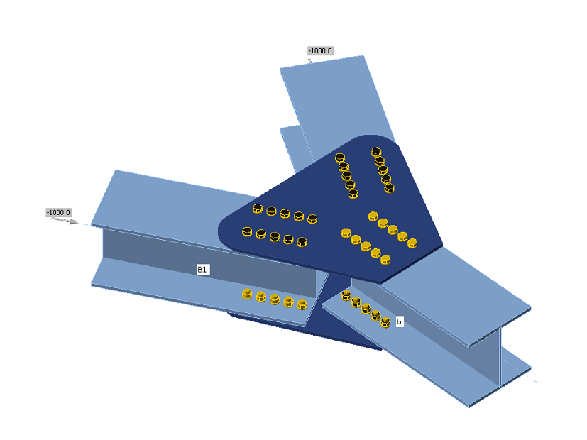
Code-check of bolts and preloaded bolts according to Canadian standards
The forces in bolts including prying forces are determined by finite element analysis. The bolt resistances are checked by S16 – Chapter 13.
Bolts
Tensile strength of bolts
The tensile resistance of a bolt is assessed according to Clause 13.12.1.3 and taken as:
\[ T_r = 0.75 \phi_b A_b F_u \]
where:
- ϕb = 0.8 – resistance factor for bolts, editable in Code setup
- Ab – cross-sectional area of a bolt based on its nominal diameter
- Fu – specified minimum tensile strength for a bolt
When the bolt threads are intercepted by a shear plane, the shear resistance is taken as 0.7 Vr.
Shear strength of bolts
The shear resistance of a bolt is assessed according to Clause 13.12.1.2. Each shear plane of a bolt is checked separately. It is taken as:
\[ V_r=0.6 \phi_b A_b F_u \]
where:
- ϕb = 0.8 – the resistance factor for bolts, editable in Code setup
- Ab – cross-sectional area of a bolt based on its nominal diameter
- Fu – specified minimum tensile strength for a bolt
When the bolt threads are intercepted by a shear plane, the shear resistance is taken as 0.7 Vr.
Combined tension and shear in bearing type connection
The resistance of a bolt loaded by combined tension and shear is assessed according to Clause 13.12.1.4 and taken as:
\[ \left ( \frac{V_f}{V_r} \right )^2 + \left ( \frac{T_f}{T_r} \right )^2 \le 1 \]
where:
- Vf and Tf are design shear force and tensile force acting on the bolt, respectively
- Vr and Tr are design shear resistance and tensile resistance of the bolt, respectively
Bearing strength in bolt holes
The resistance developed at the bolt in a bolted joint subjected to bearing and shear is assessed according to Clause 13.12.1.2 and taken as
Br = 3 ϕbr t d Fu for regular bolt holes
Br = 2.4 ϕbr t d Fu for slotted holes loaded perpendicular to these holes
where:
- ϕbr = 0.8 – resistance factor for the bearing of bolts on the steel
- t – thinner thickness of connected plates
- d – diameter of a bolt
- Fu – tensile strength of the connected material
Hole tear-out of a bolt
The resistance of hole tear-out of a bolt is checked for individual bolts according to Clause 13.11 as:
\[ T_r = \phi_u 0.6 A_{gv} \frac{F_y+F_u}{2} \]
where:
- ϕu = 0.75 – resistance factor for structural steel
- Agv = 2 ∙ l ∙ t – gross area in shear
- Fy – yield strength of the connected material
- Fu – tensile strength of the connected material
- l – distance from the centreline of the bolt to the edge in the direction of the shear force
- t – thickness of the connected material
For steel grades with Fy > 460 MPa, (Fy + Fu) / 2 shall be replaced with Fy in the determination of Tr.
Bolts in slip-critical connections
The slip resistance of a bolted joint is assessed according to Clause 13.12.2 as
Vs = 0.53 cs ks Ab Fu
where:
- cs – coefficient determined according to ks and bolt grade:
- for ks < 0.52 class A cs = 1.00 (A325) or 0.92 (A490) or 0.78 (other)
- for ks ≥ 0.52 class B cs = 1.04 (A325) or 0.96 (A490) or 0.81 (other)
- ks – friction coef. editable in Code setup which should be set according to Table 3 in S16-14; equals 0.3 for class A or 0.52 for class B
- Ab – cross-sectional area of a bolt based on its nominal diameter
- Fu – specified minimum tensile strength for a bolt
When slotted holes are used in slip-critical connections, Vs = 0.75 ∙ 0.53 cs ks Ab Fu.
A bolt subjected to both tension and shear must satisfy the following relationship:
\[ \frac{V_f}{V_s}+1.9\frac{T}{A_b F_u} \]
where:
- Vf and Tf are the design shear force and the tensile force acting on the bolt, respectively
Clause 13.12.2 states that the resistances of the connection as specified in Clause 13.12.1 shall be checked. The user should, therefore, check the state after slip occurs, i.e. change the shear force transfer of bolts from “Friction” to “Bearing – tension and shear interaction”.
Detailing
In the detailing of bolted connections, the minimum pitch and minimum edge distance are checked according to S16-14 – 22.3. Minimum pitch (2.7 d – editable in Code setup) and minimum edge distance (1.25 d) are checked.


