Autodesk Robot Structural Analysis Professional legătură BIM pentru proiectarea elementelor metalice (EN)
Cum se activează legătura
- Descărcați și instalați cea mai recentă versiune a IDEA StatiCa
- Asigurați-vă că utilizați o versiune compatibilă a soluției dvs. FEA
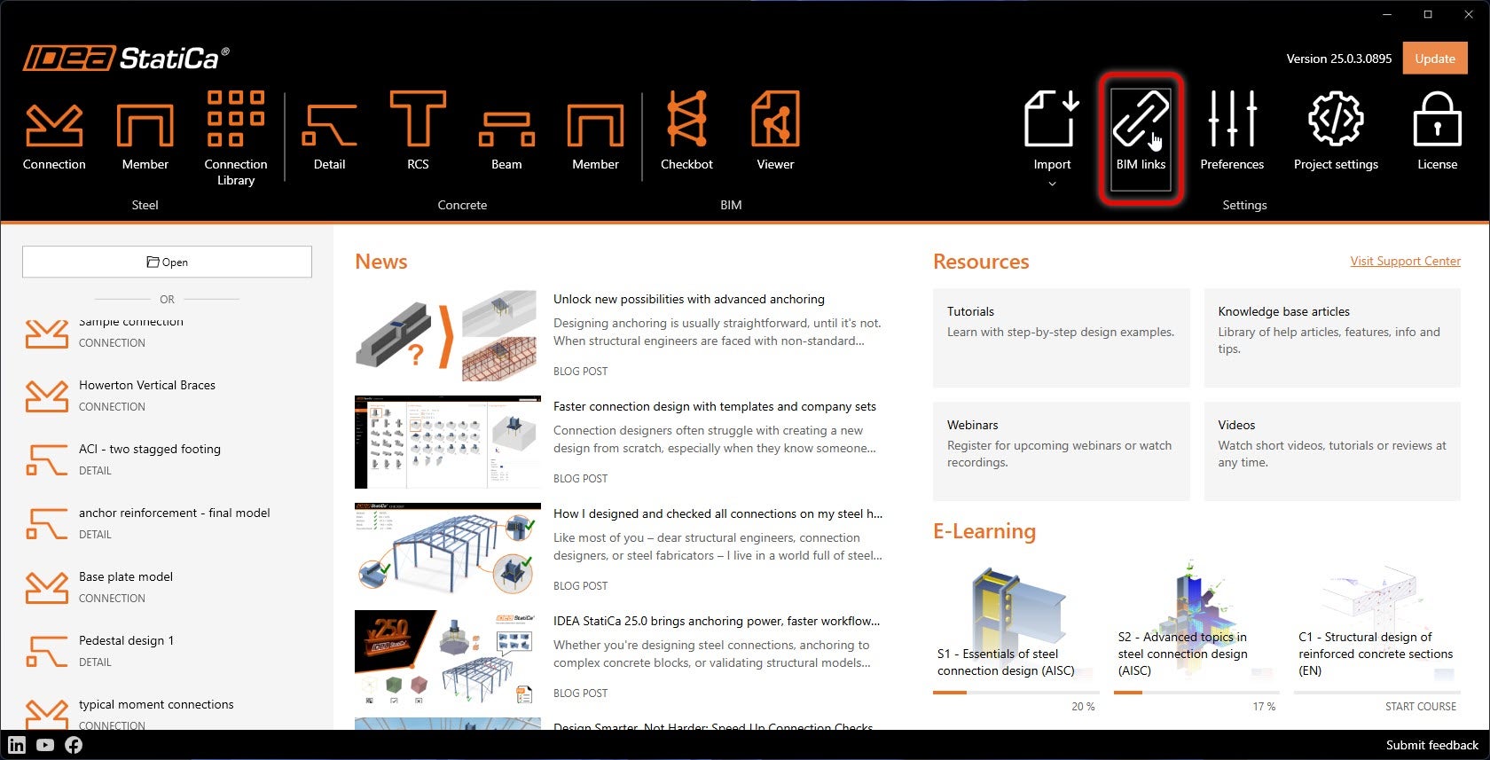
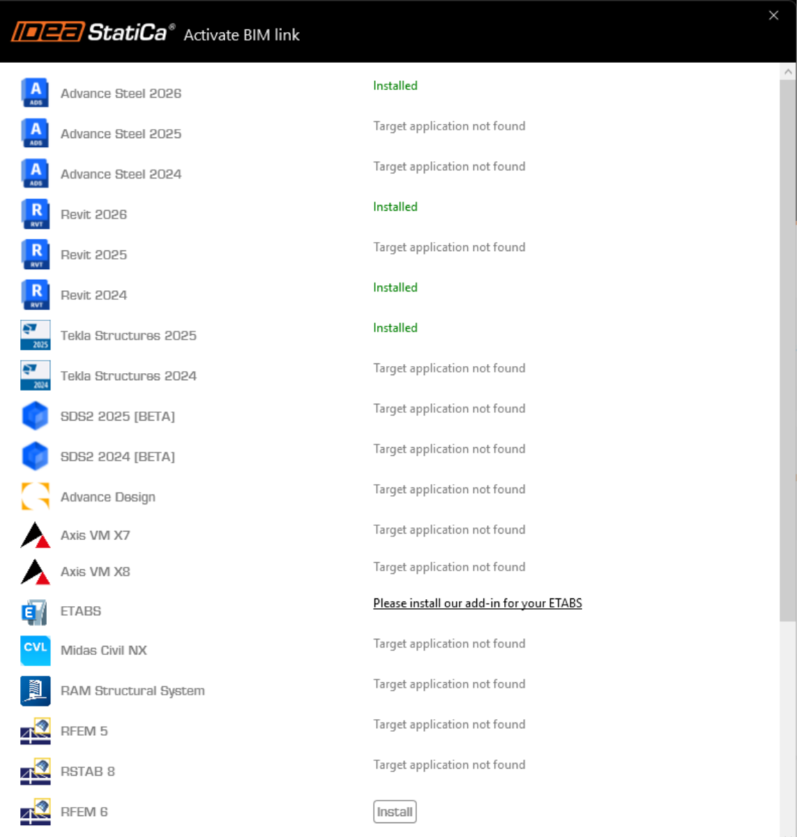
IDEA StatiCa integrează legăturile BIM în software-ul dvs. FEA în timpul instalării. Puteți verifica starea și, dacă este necesar, puteți integra mai multe legături BIM rulând IDEA StatiCa și deschizând BIM links. Rețineți că unele software-uri FEA necesită pași suplimentari pentru a activa complet legătura BIM cu IDEA StatiCa.
Este posibil să apară o notificare „Doriți să permiteți acestei aplicații să facă modificări pe dispozitivul dvs.?"; dacă da, confirmați cu butonul Da.
Făcând clic pe Install, legătura BIM pentru software-ul selectat este integrată. Ecranul vă indică, de asemenea, starea celorlalte legături BIM.
Cum se utilizează legătura
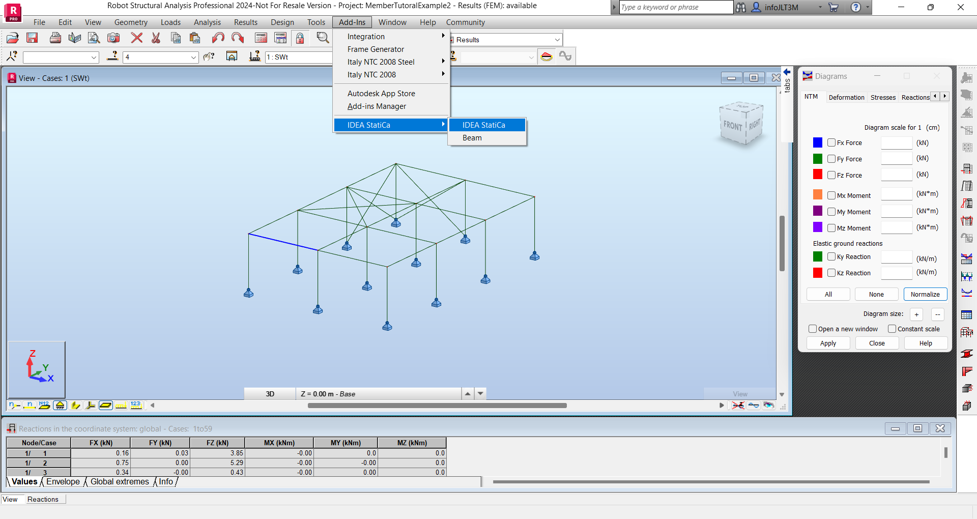
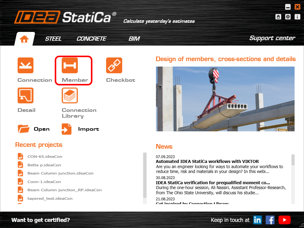
Mai întâi, deschideți fișierul sursă ARSAP-Member-Tutorial.rtd din fișierele furnizate pentru descărcare (la sfârșitul acestui tutorial). Navigați la meniul Add-ins, apoi IDEA StatiCa și rulați IDEA StatiCa. Aceasta va porni Checkbot.
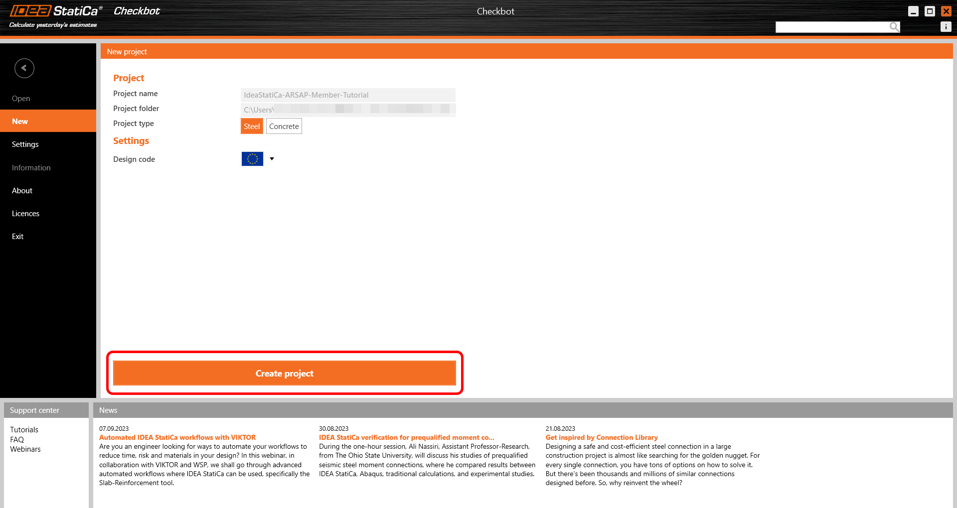
Vi se va solicita să creați un proiect nou.
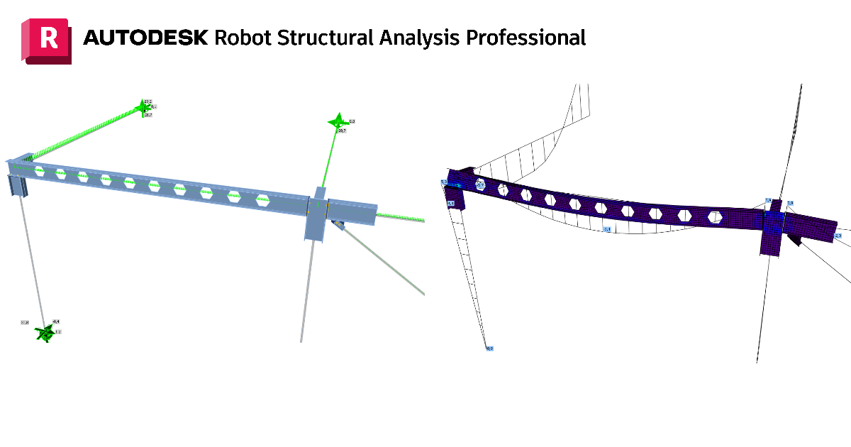
Checkbot se deschide și puteți începe procesul de import. Selectați grinda indicată în modelul Robot și faceți clic pe Member pentru a o importa în vederea analizei în IDEA StatiCa Member conform codului EN.
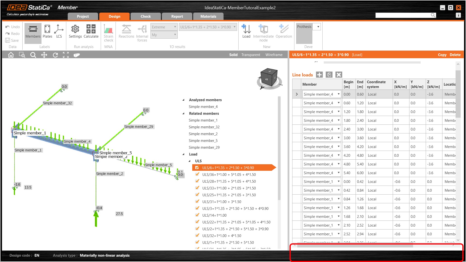
Elementul este adăugat în listă împreună cu nodurile corespunzătoare, elementele conexe și combinațiile de încărcări, fără a fi necesară introducerea manuală a acestora. Lăsați setările implicite și începeți mai întâi configurarea îmbinărilor.
Utilizarea legăturii BIM în acest mod vă permite nu numai să proiectați elementele, ci și îmbinările. Dacă vă amintiți, în cadrul aplicației Member, îmbinările nu pot fi proiectate, ci doar modelate. În cadrul Checkbot, îmbinările pot fi modelate și proiectate folosind combinațiile de încărcări din aplicația FEA. Aceste îmbinări rezultante pot fi apoi reutilizate la proiectarea elementului. Ca urmare, îmbinările sunt proiectate mai eficient.
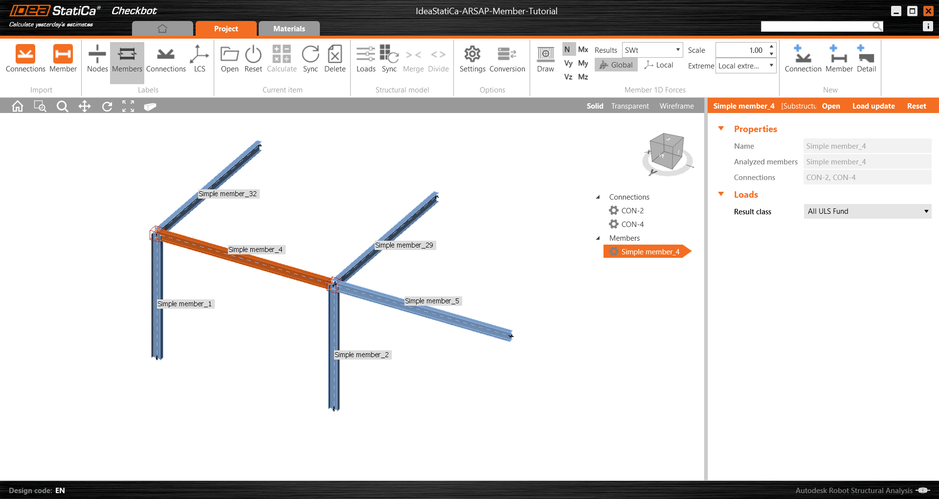
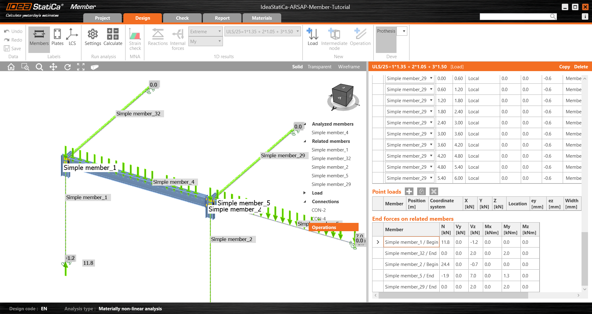
Deschideți Simple member_4 pentru a vedea lista completă a elementelor, îmbinărilor și combinațiilor de încărcări.
Proiectare
Există două moduri în care putem proiecta elementul și îmbinările sale:
- Online - în timp real în Checkbot, menținând legătura cu aplicația FEA
- Offline - tot în Checkbot, dar utilizând datele din aplicația FEA
Pentru ușurință (și pentru a-i ajuta pe cei care nu dețin Autodesk Robot Structural Analysis Professional), vom reveni acum la o abordare offline. Dosarul proiectului poate fi de asemenea descărcat și extras folosind linkul de la sfârșitul acestui tutorial.
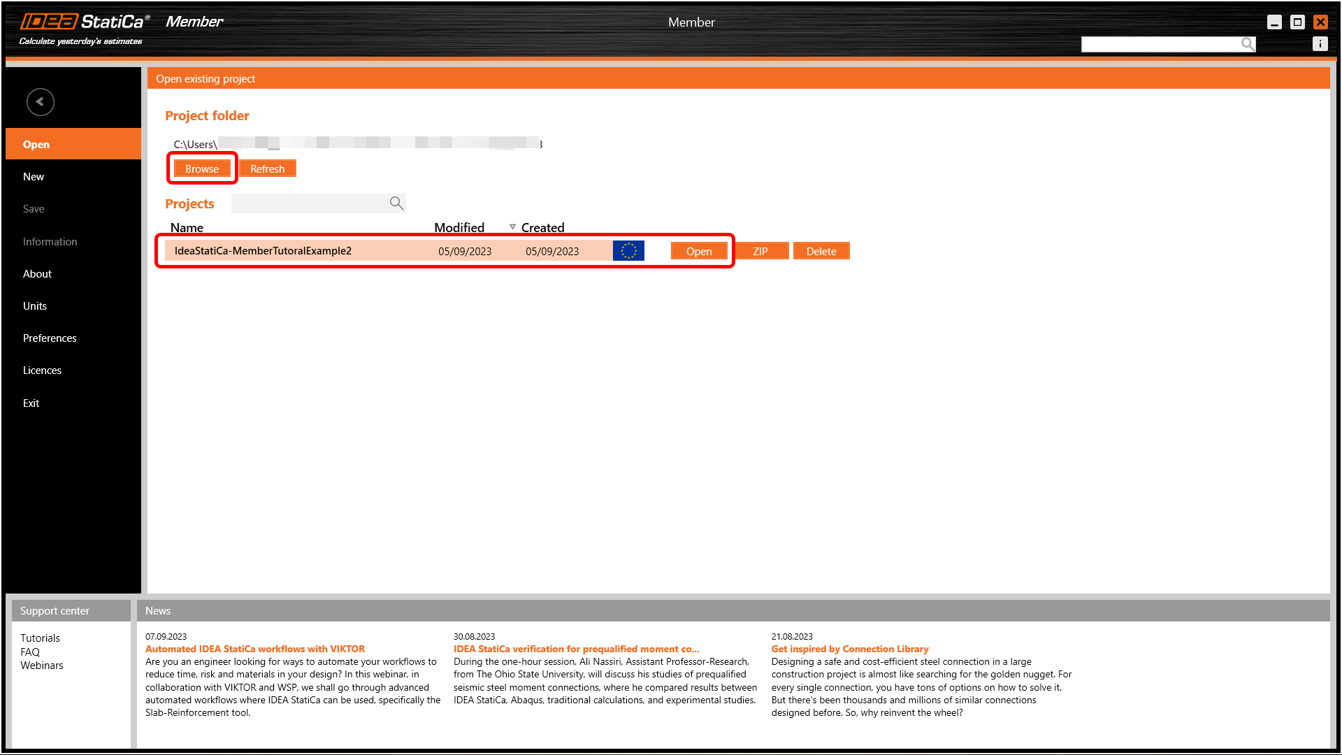
Puteți ieși din Checkbot și Robot, apoi deschideți proiectul în Member navigând până la acesta.
Aceasta va deschide aplicația Member în așa-numitul mod offline - puteți verifica acest lucru deoarece nu va fi afișată nicio aplicație în bara de informații din partea de jos a ecranului.
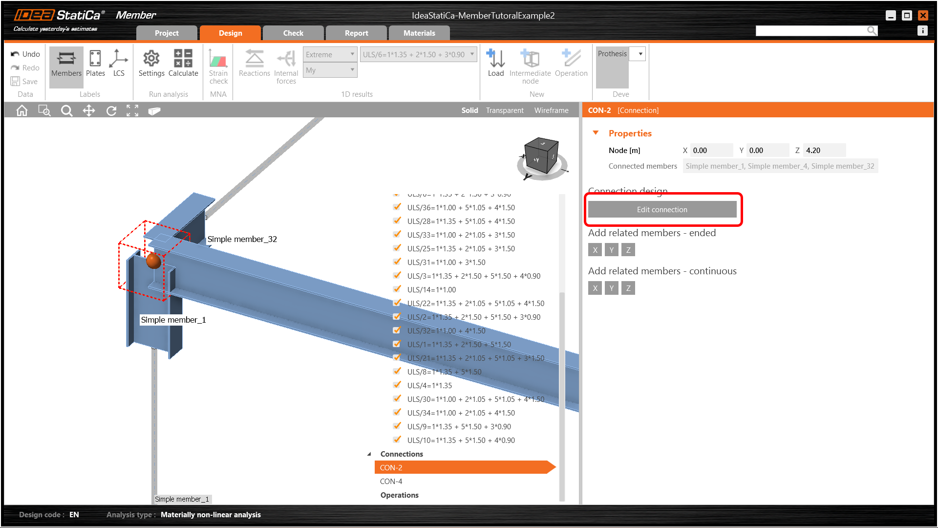
Putem continua acum selectând CON-2 și apăsând Edit Connection.
Aceasta va deschide familiara aplicație IDEA StatiCa Connection. Aplicați o operație de tăiere a elementului stâlp pentru a-i mări înălțimea cu 20 mm față de talpa superioară a grinzii.
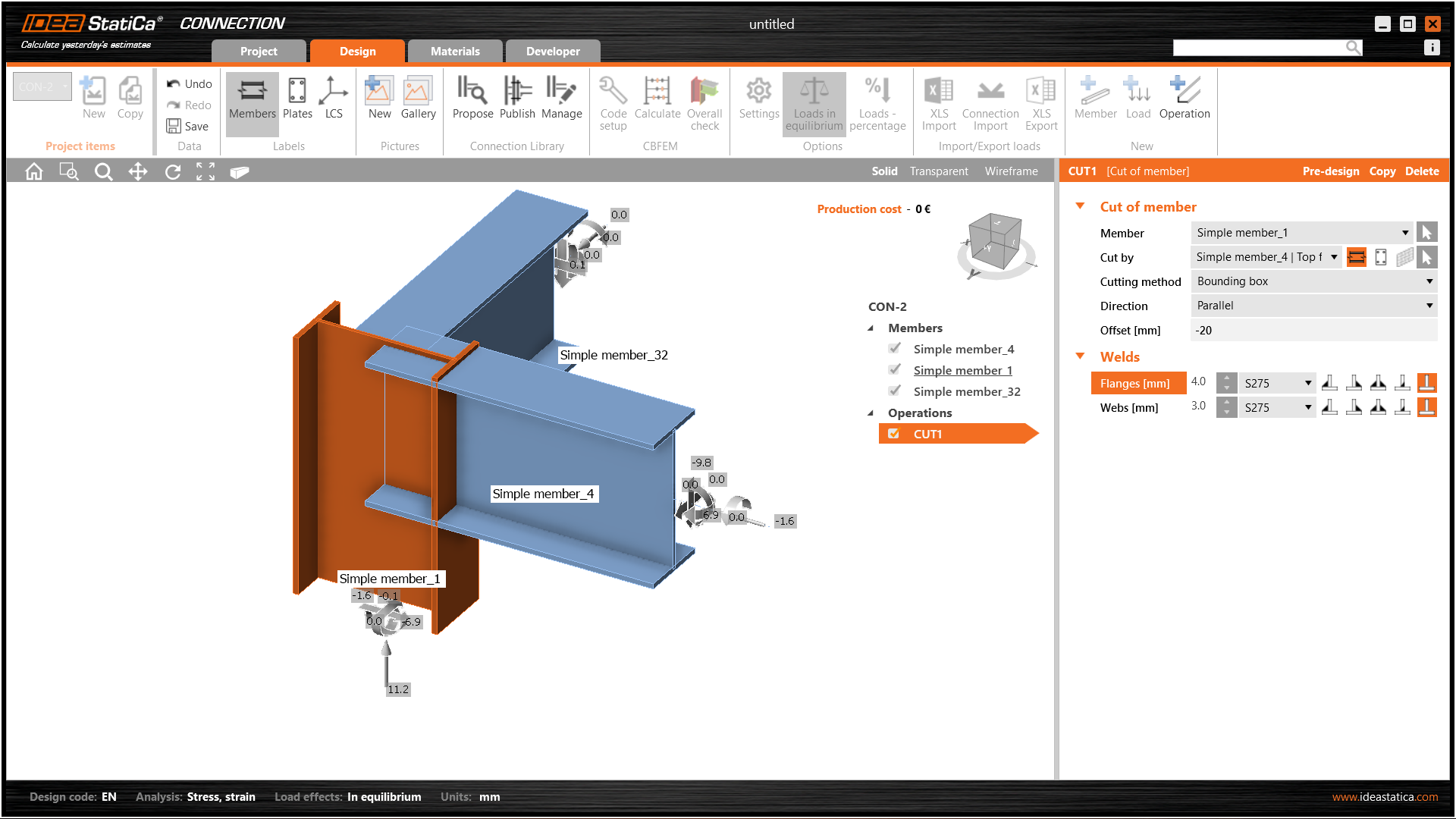
Aplicați apoi o placă de capăt simplă la ambele grinzi - rețineți că puteți copia operații.
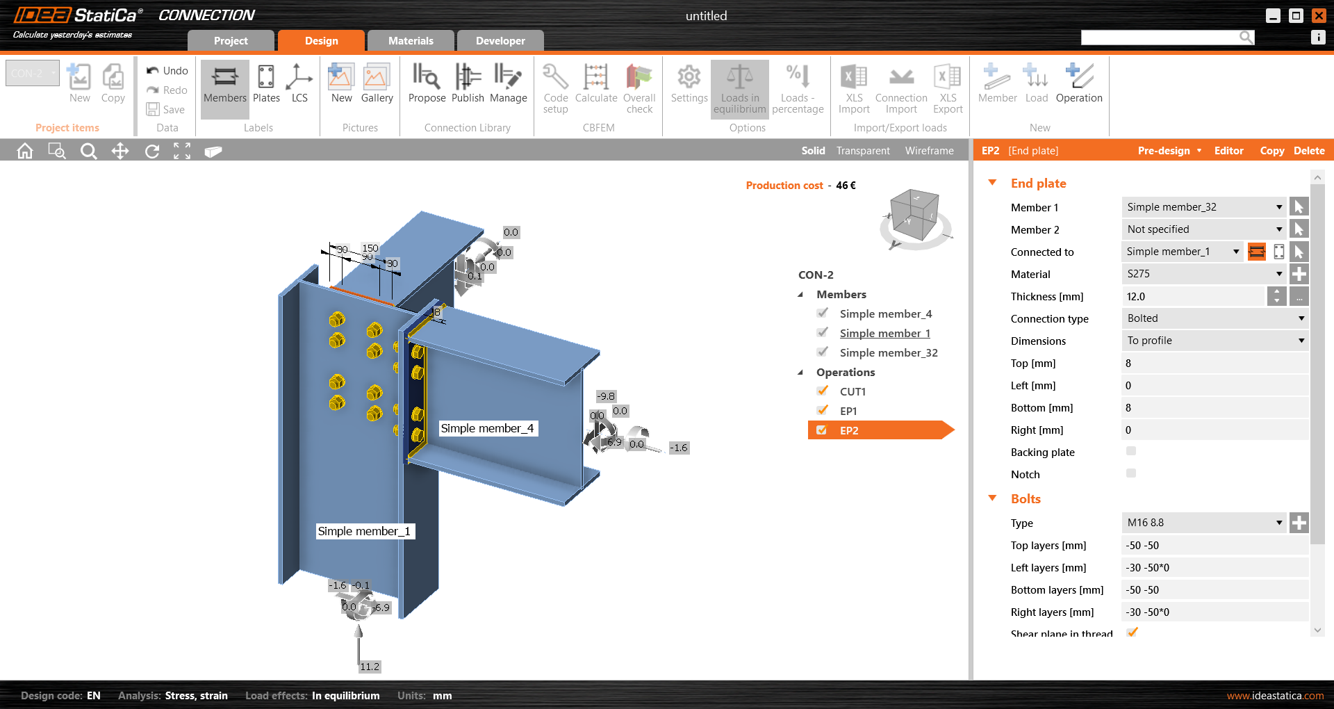
Salvați această îmbinare și ieșiți în aplicația Member.
În acest exemplu, toate elementele au aceleași dimensiuni, astfel încât puteți aplica rapid aceleași operații pentru Con-4.
Aceasta este aspectul final al Con-4.
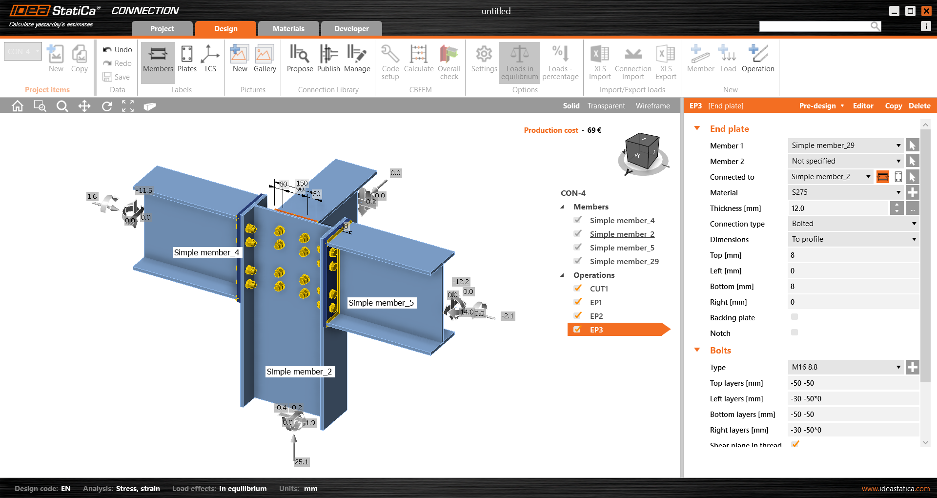
Salvați din nou acest model de îmbinare și reveniți la aplicația Member. Îmbinările modelate vor fi vizibile.
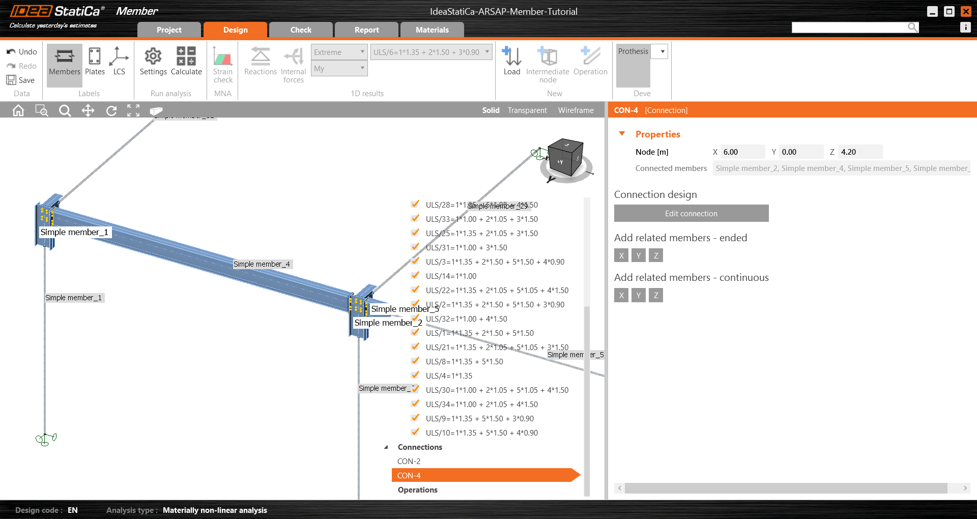
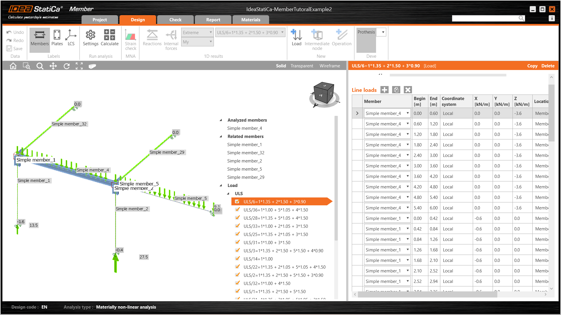
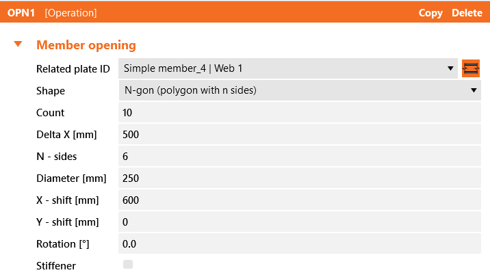
Toate datele, cum ar fi geometria și încărcările, au fost importate, iar toate îmbinările au fost proiectate. Modelul este pregătit pentru analiză, dar mai întâi, să adăugăm câteva goluri în inima elementului. Selectați elementul, apoi în Operații din meniul arborescent și alegeți operația Opening.
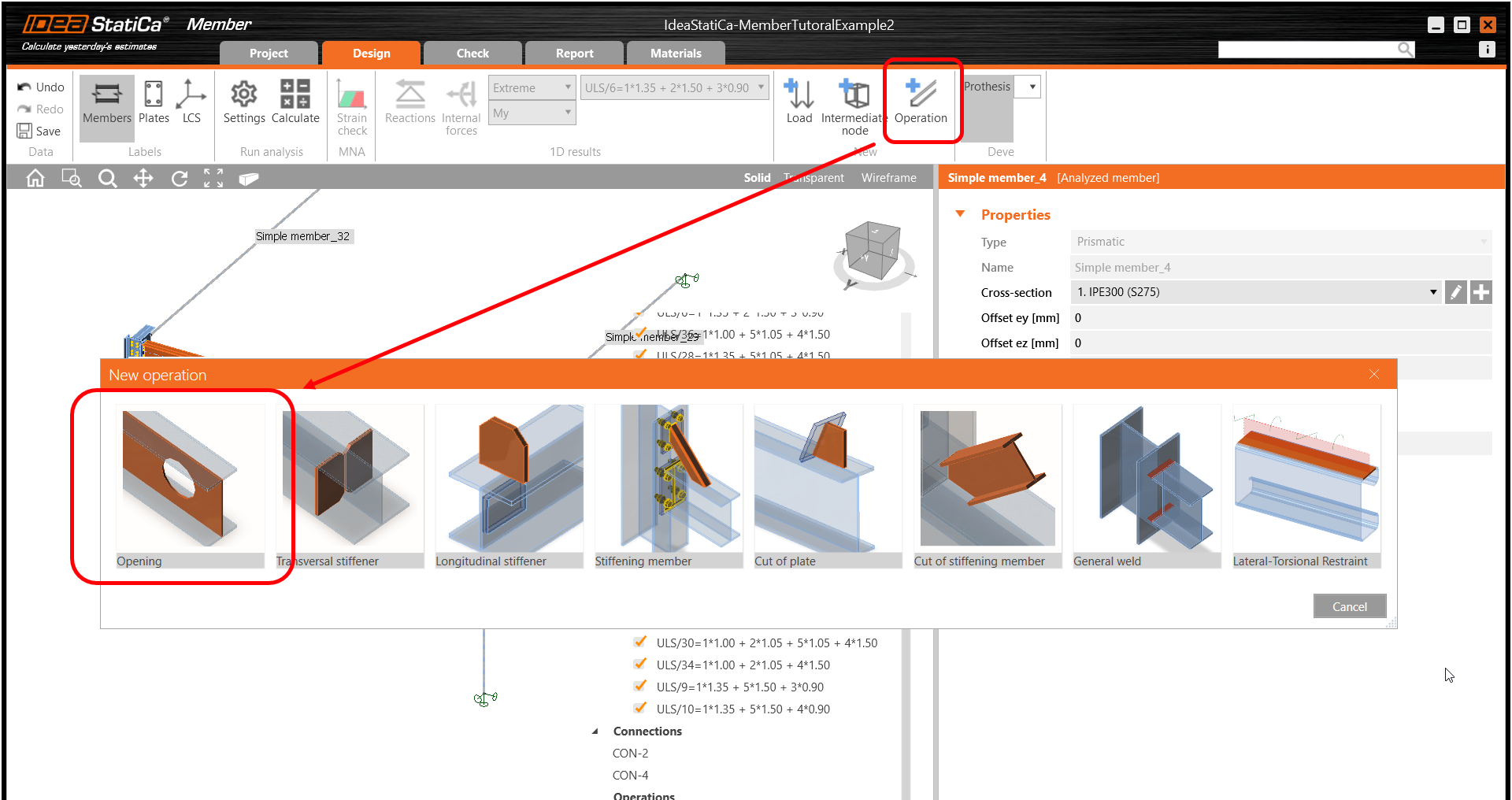
Editați parametrii operației, modificați dimensiunea și forma în N-gon (poligon cu n laturi) și multiplicați numărul de goluri.
Verificare
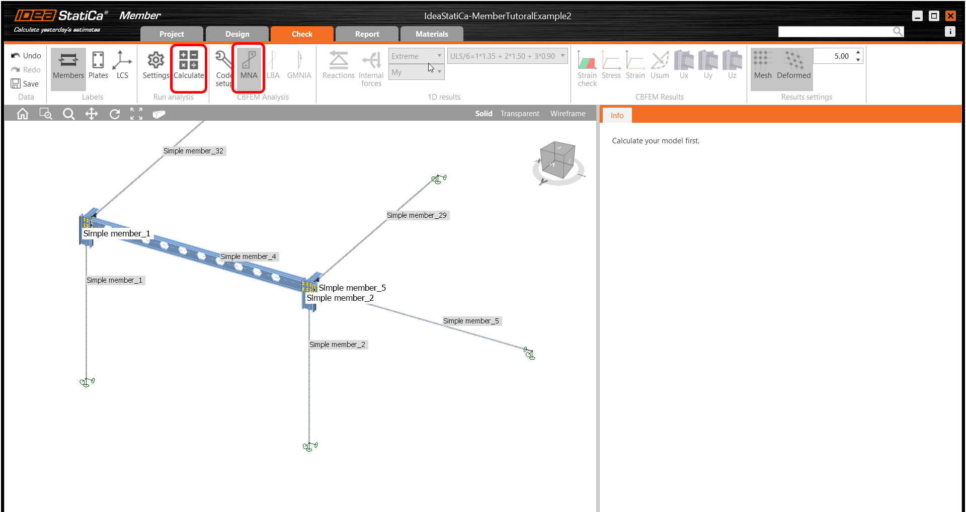
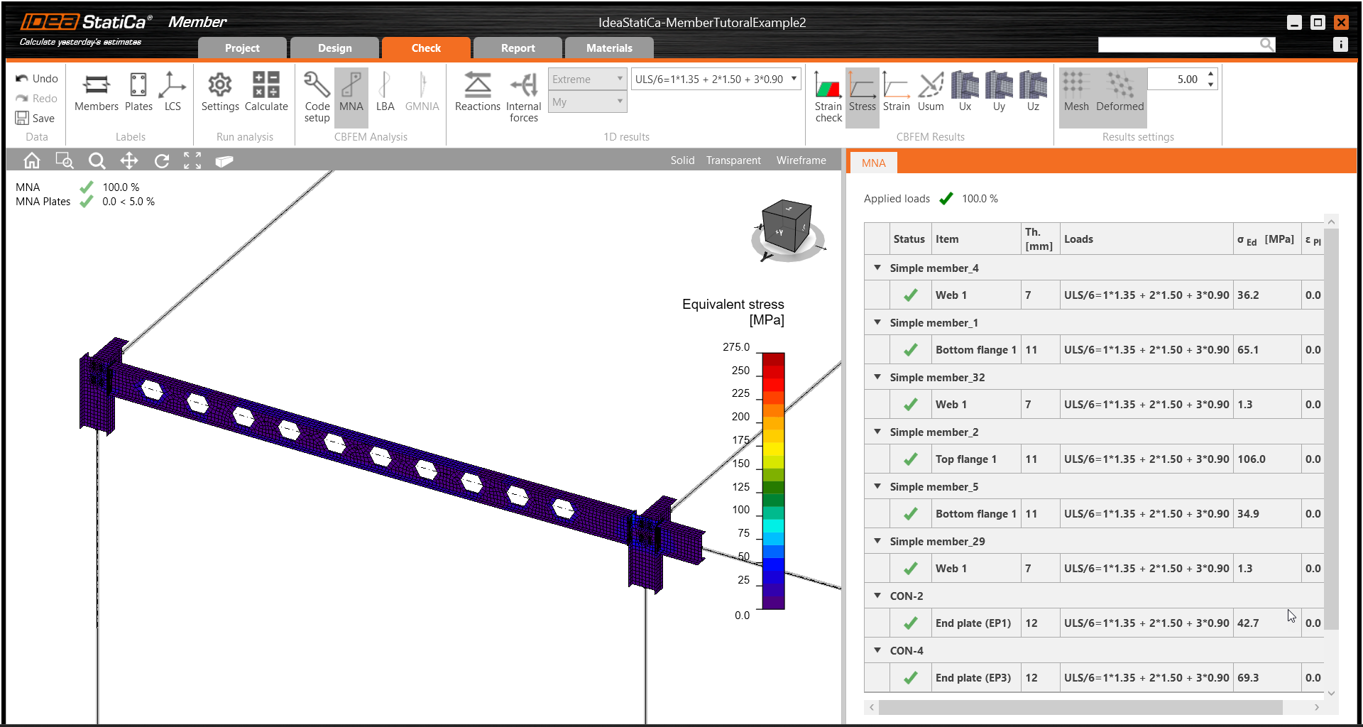
Treceți la fila Check, selectați MNA (Analiza Materială Neliniară) și porniți analiza făcând clic pe Calculate în panglică. Modelul de analiză este generat automat, calculul este efectuat și puteți vedea verificarea globală afișată împreună cu valorile de bază ale rezultatelor verificării.
În pasul următor, comutați tipul de analiză la LBA (Analiza liniară de flambaj) și rulați din nou analiza făcând clic pe Calculate.
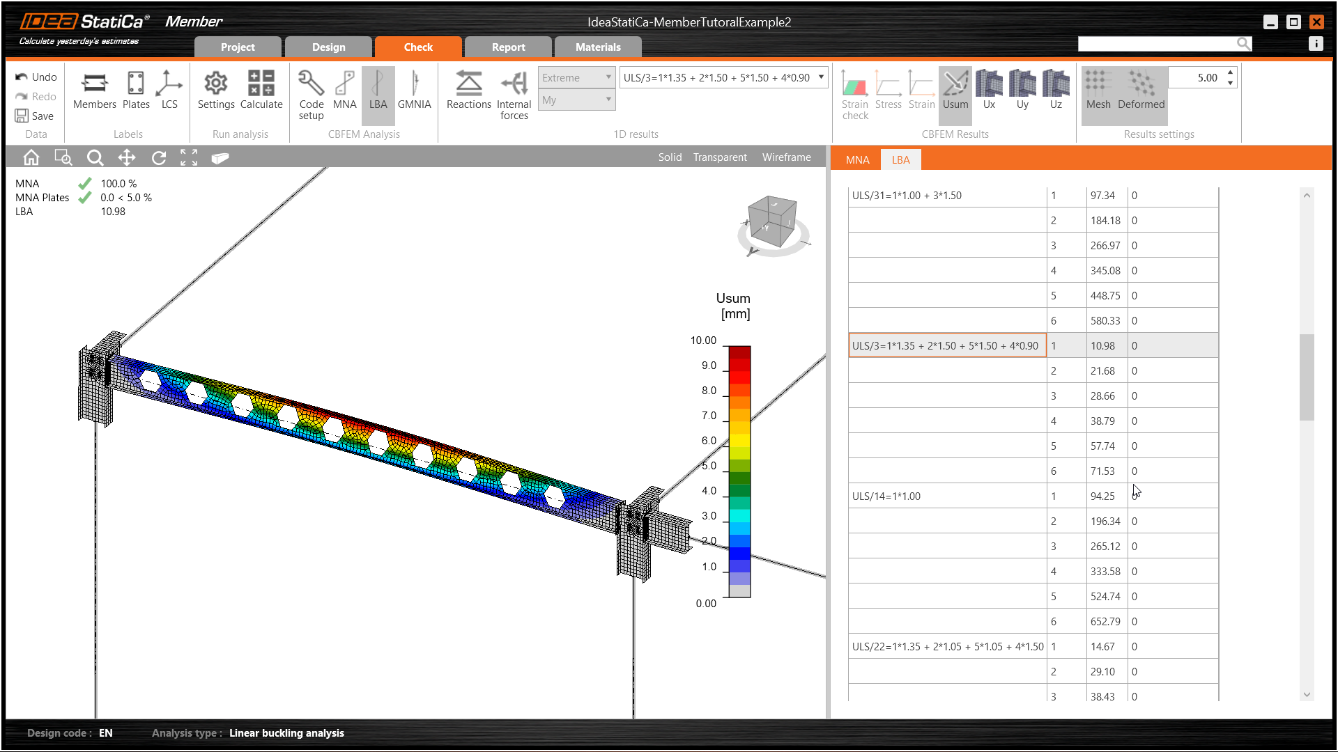
Când analiza este finalizată, puteți naviga prin factorii formei de flambaj din filă, iar selectând una, de ex. forma de flambaj 1, o puteți vedea vizualizată în fereastra 3D. Selectarea afișării rezultatelor Uy evidențiază tendința de deformare.
Acum puteți calcula GMNIA (analiza geometrică și materială neliniară cu imperfecțiuni). Conform EN 1993-1-1, alegeți forma de flambaj cea mai critică sau o combinație de forme de flambaj și introduceți imperfecțiunea inițială a grinzii critice. În acest caz, forma de flambaj 1 este cea mai critică. Comutați la fila GMNIA din panoul din dreapta și determinați imperfecțiunea de 10 mm (0,5xL/300 = 0,5*6000/300 = 10 mm) pentru a o introduce ca Amplitudine în coloana 1. Faceți clic pe butonul Calculate; pentru această analiză, calculul poate dura câteva minute.
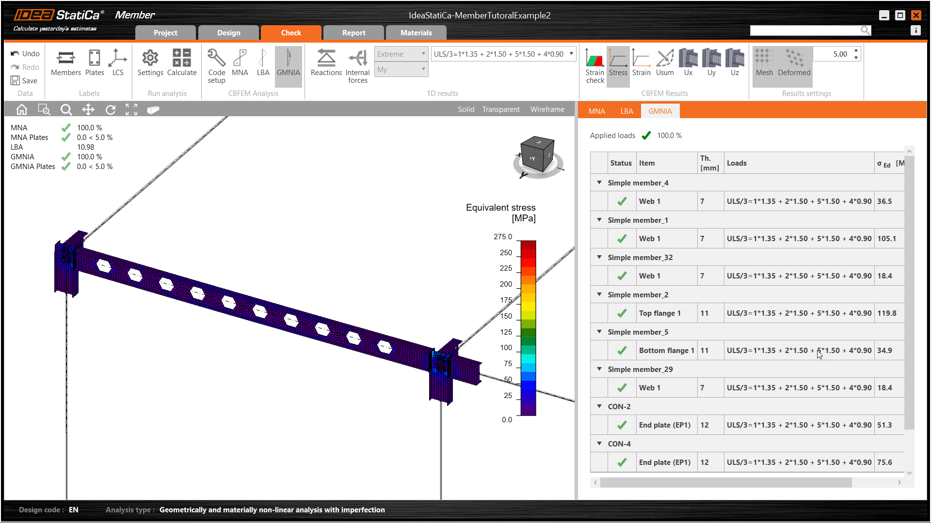
Elementul a trecut verificările conform codului cu imperfecțiunile inițiale aplicate și putem naviga prin rezultate, cum ar fi distribuția tensiunilor și diagrama forțelor interioare.
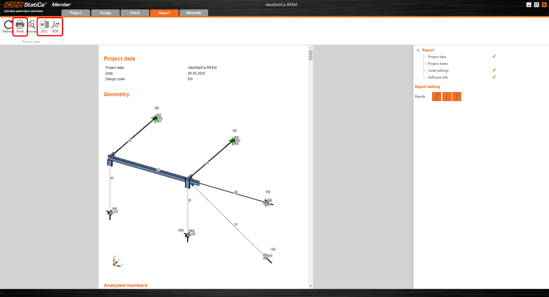
Raport
În final, accesați fila Report. IDEA StatiCa oferă un raport complet personalizabil care poate fi tipărit sau salvat în format .pdf sau .doc pentru un format editabil.
Ați importat un element din Autodesk Structural Analysis Professional, l-ați proiectat și verificat conform codului Eurocode (EN).
Salvați proiectul în IDEA StatiCa Member și închideți-l. Procesul următor este disponibil doar atunci când lucrați online, în timp real cu modelul FEA și Checkbot, și oferă economii considerabile de timp atunci când apar modificări.
Sincronizarea modelelor
În loc să recreați modelele de fiecare dată când FEA se modifică, Checkbot poate sincroniza informațiile sale cu cele ale aplicației FEA.
Pentru a demonstra funcția de sincronizare, modificați secțiunea transversală a elementului analizat.
Apoi, recalculați proiectul în Autodesk Robot Structural Analysis Professional și deschideți din nou Checkbot.
Selectați elementul din listă și faceți clic pe Sync din panoul Current item sau pe Sync din panoul Structural model pentru a actualiza întregul model.
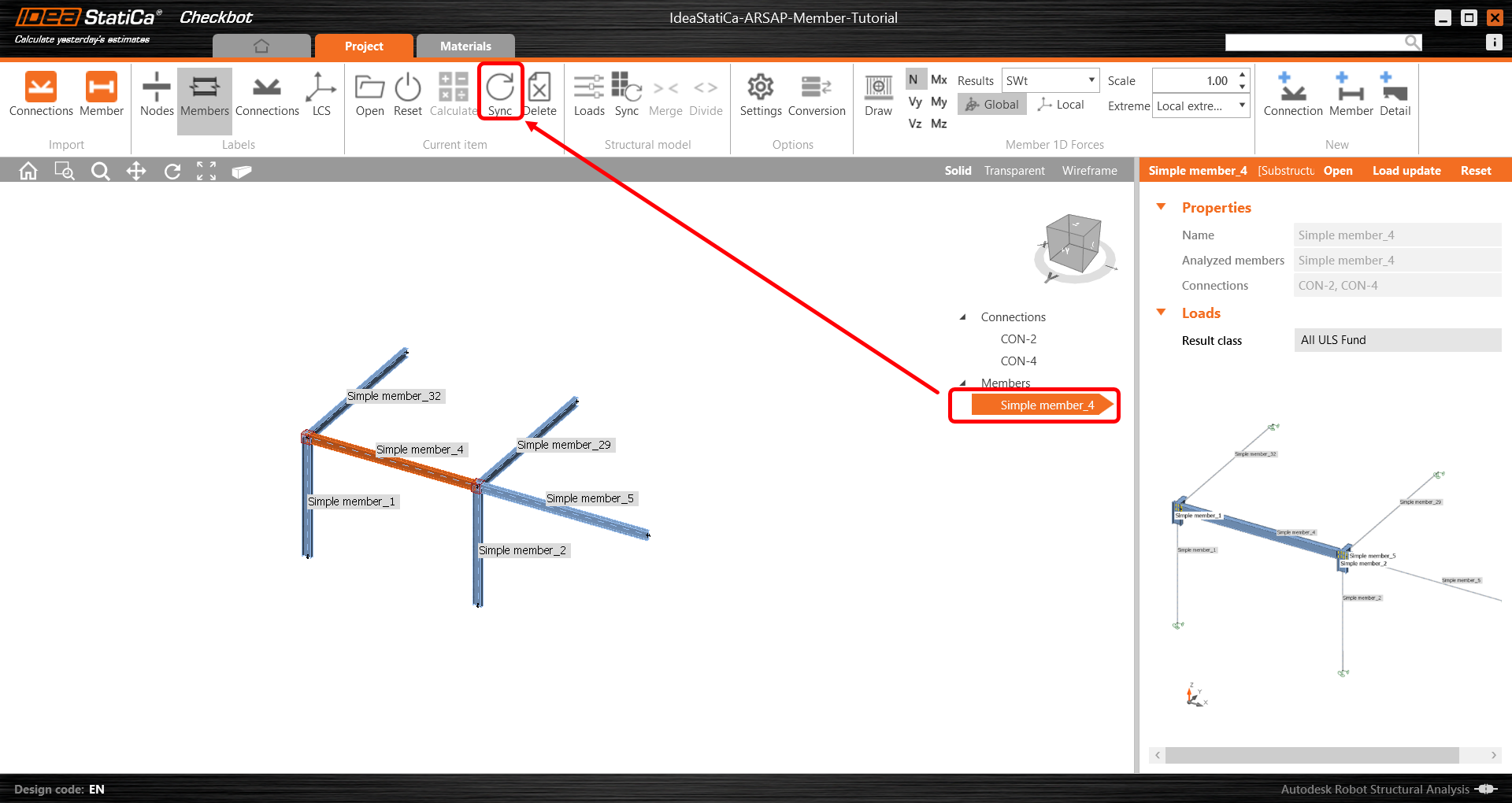
Geometria și încărcările au fost actualizate și puteți face clic pe Open pentru a verifica elementul din proiect.
IDEA StatiCa se deschide și puteți vedea geometria actualizată, în timp ce operațiile de proiectare își păstrează setările. Cu toate acestea, rețineți că unele modificări pot conduce la o proiectare invalidă și, ca atare, aceste modificări ar trebui să fie supuse unui proces riguros de revizuire a proiectării.
Puteți verifica și ajusta proiectarea, recalcula și efectua verificarea conform codului a elementului, salva și închide. Apoi puteți continua importul și verificarea conform codului a mai multor noduri sau elemente.
Doriți să vă îmbunătățiți competențele? Vizitați Campus-ul nostru
CONȚINUT ASOCIAT
Lungimea implicită a elementului în Connection
Descărcări atașate
- Start - IdeaStatiCa-MemberTutorialExample.zip (ZIP, 306 kB)
- ARSAP-Member-Tutorial.rtd (RTD, 920 kB)