Proiectarea structurală și verificarea conform codului a unui cadru metalic (EN)
1 Proiect nou
Începeți prin lansarea IDEA StatiCa și selectați aplicația Member (descărcați cea mai recentă versiune).
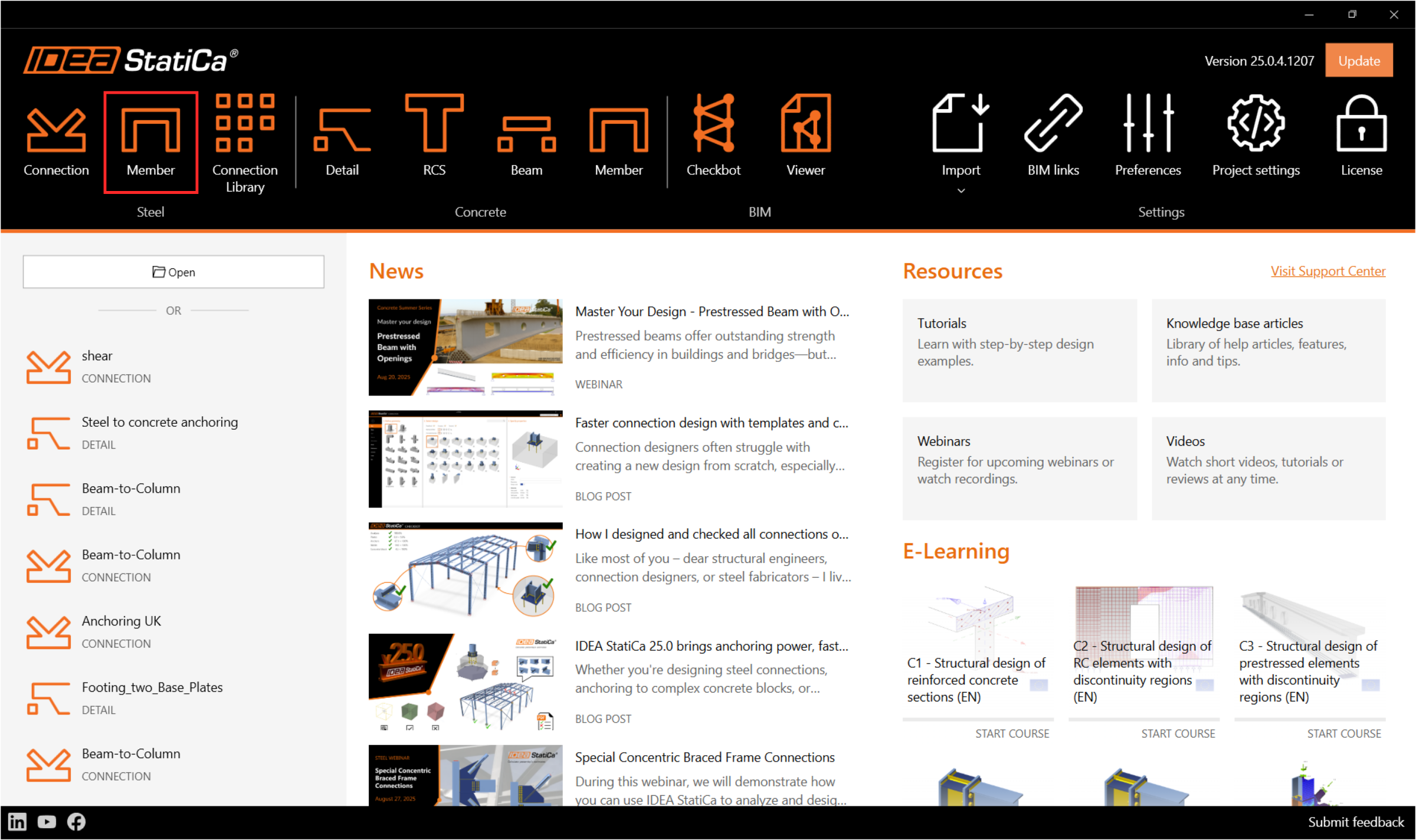
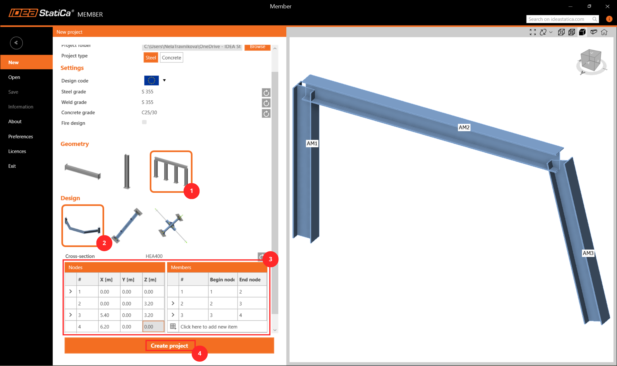
Creați un proiect nou, introduceți numele acestuia și selectați un folder în care va fi salvat. Apoi alegeți codul de proiectare, proprietățile inițiale ale materialelor și tipul de topologie. Adăugați coordonatele nodurilor detaliului structural și adăugați elementele între aceste noduri. În final, faceți clic pe Create Project și începeți modelarea detaliului structural.
2 Elemente analizate
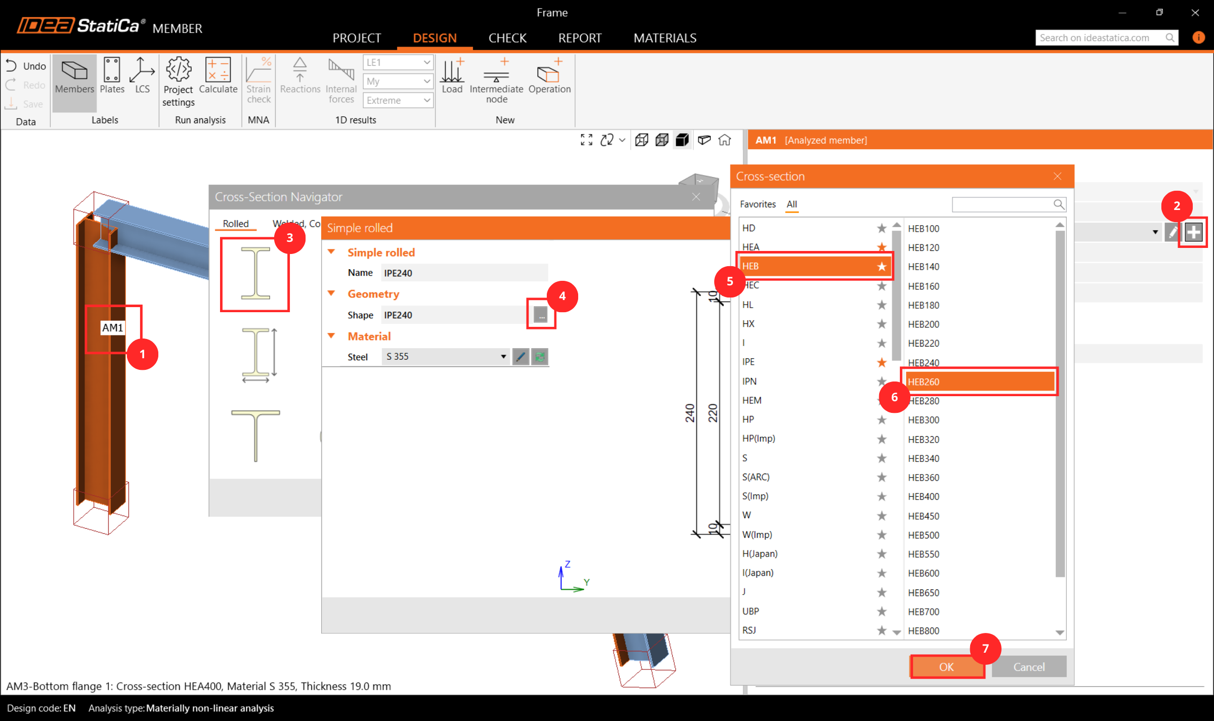
Aici puteți vedea și modifica parametrii elementelor adăugate pentru analiză. Schimbați secțiunea transversală a stâlpului AM1 la HEB260.
3 Elemente conexe
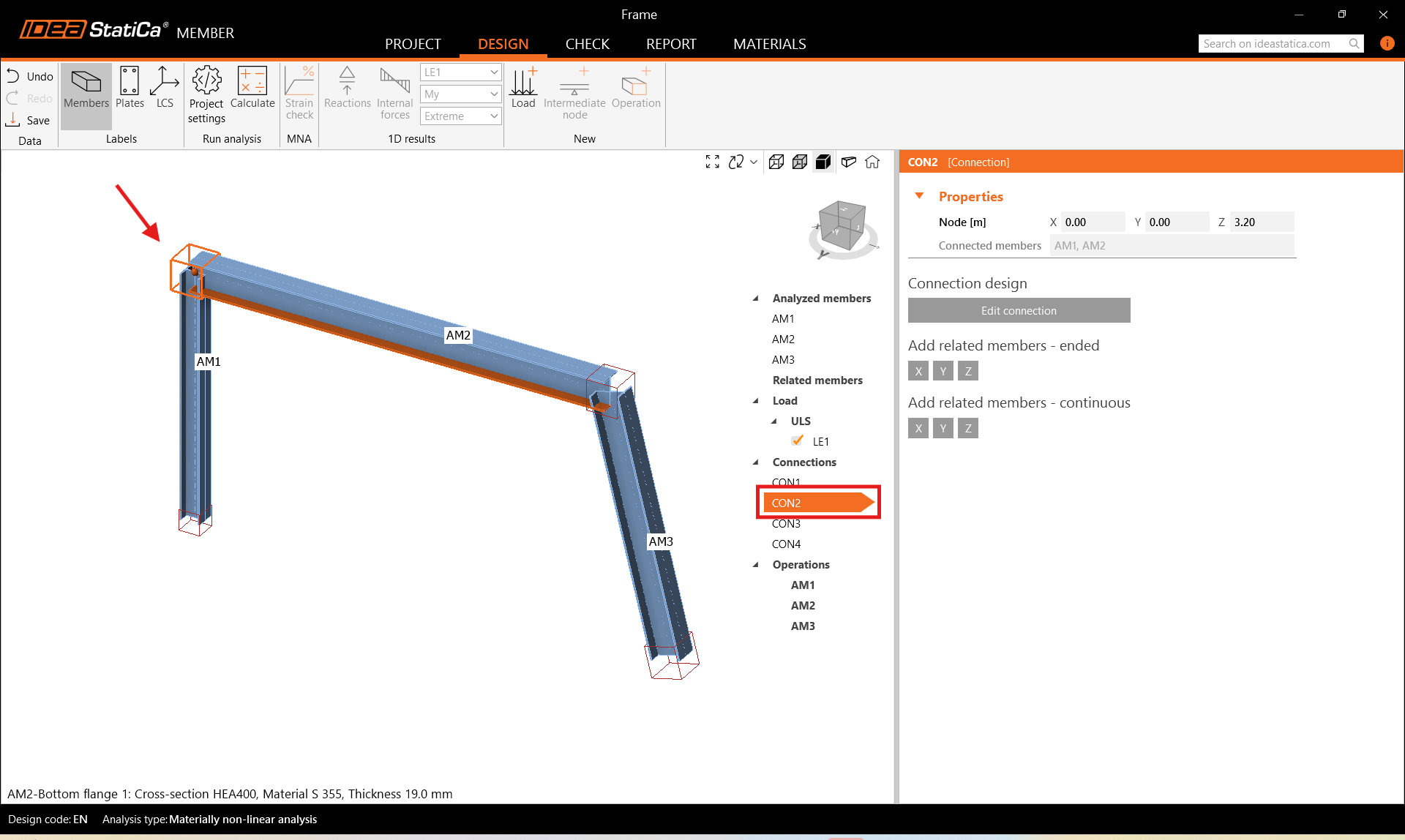
Pentru a adăuga elemente conexe, care acționează ca reazeme și părți de transfer al încărcărilor pentru detaliul structural, faceți clic pe cubul nodului în scena 3D sau selectați CON# din lista arborescentă. Aici puteți adăuga elemente conexe cu capete libere sau continue, făcând clic pe direcțiile axelor X, Y, Z conform sistemului de coordonate global. Adăugați 2 elemente cu capete libere în direcția Y.
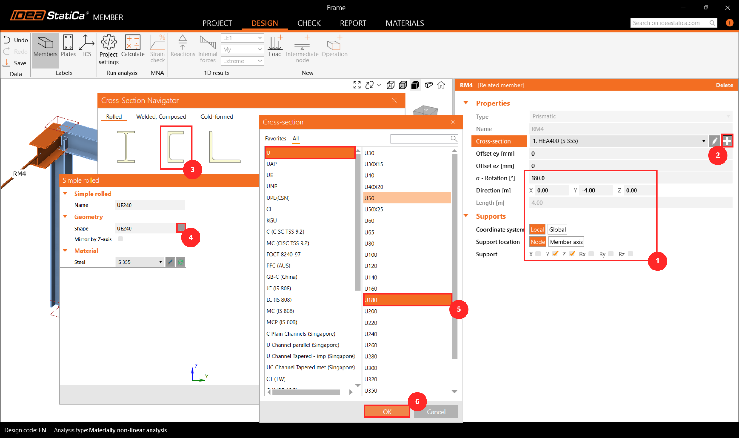
Apoi selectați elementul conex RM4 fie în scena 3D, fie din lista arborescentă și modificați proprietățile acestuia: secțiunea transversală, lungimea, orientarea și rezemările la capetele libere.
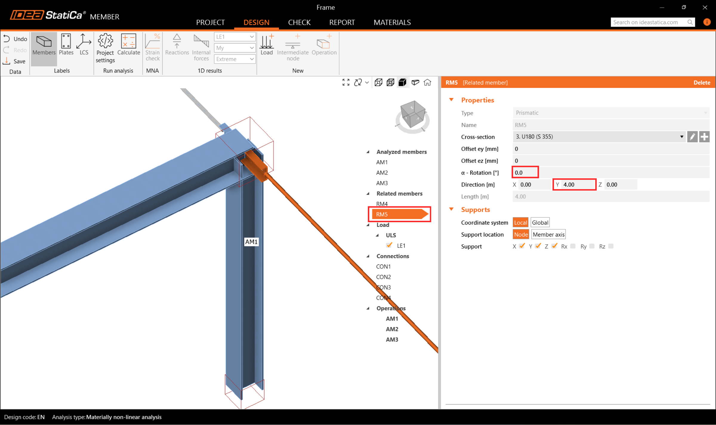
Și modificați elementul conex RM5 în mod corespunzător.
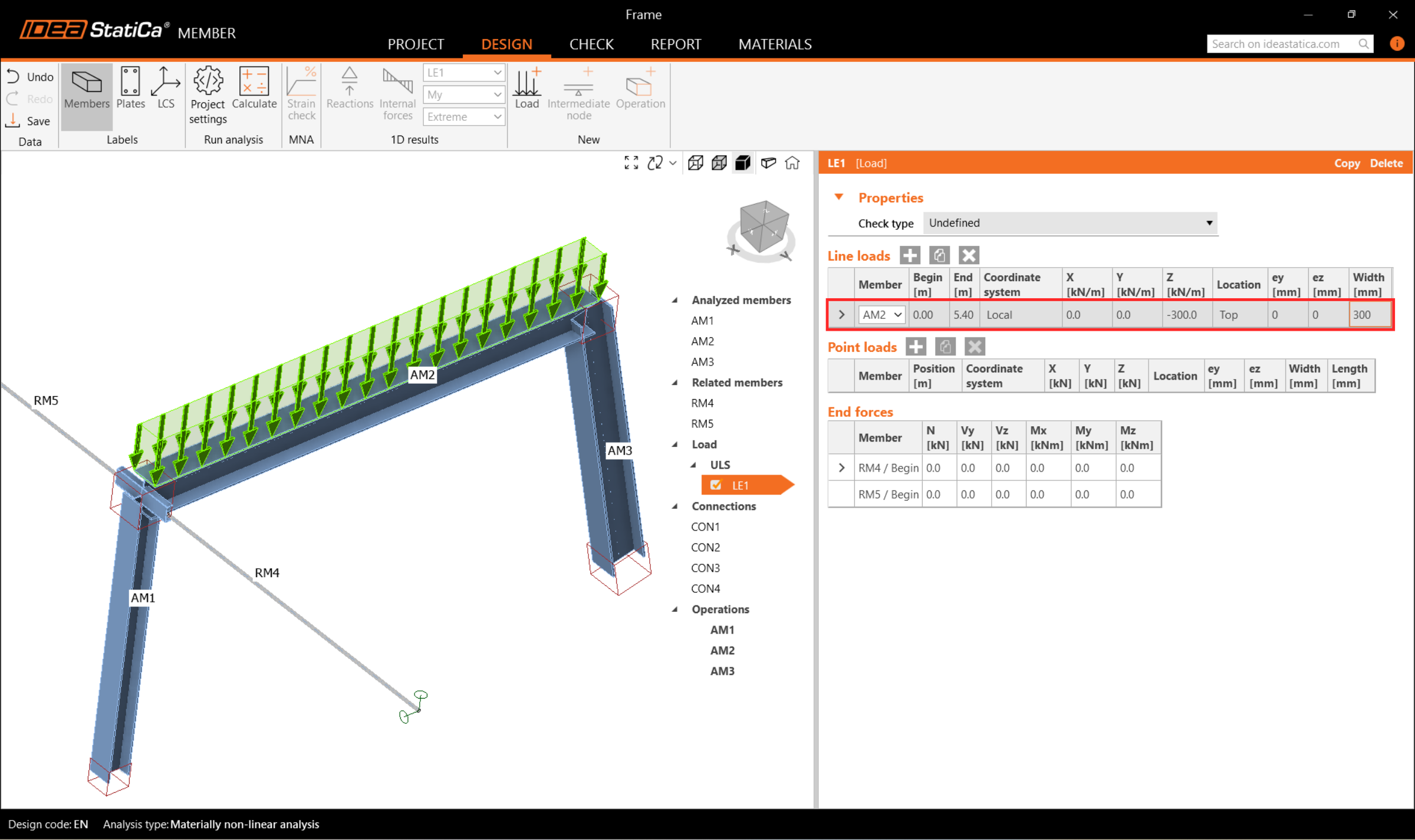
4 Încărcări
În meniul Loads, puteți adăuga și modifica efectele încărcărilor. Un efect al încărcării reprezintă un grup în care puteți adăuga una sau mai multe încărcări distribuite pe orice element analizat sau conex. Alternativ, în cadrul unui efect al încărcării, puteți introduce forțe interioare nodale la capetele elementelor.
Un efect al încărcării conținând un set de încărcări liniare a fost generat automat pentru toate elementele. Ștergeți 2 dintre ele făcând clic cu butonul stâng al mouse-ului pe fiecare rând din filă și selectând Delete sau făcând clic pe pictograma din panglică.
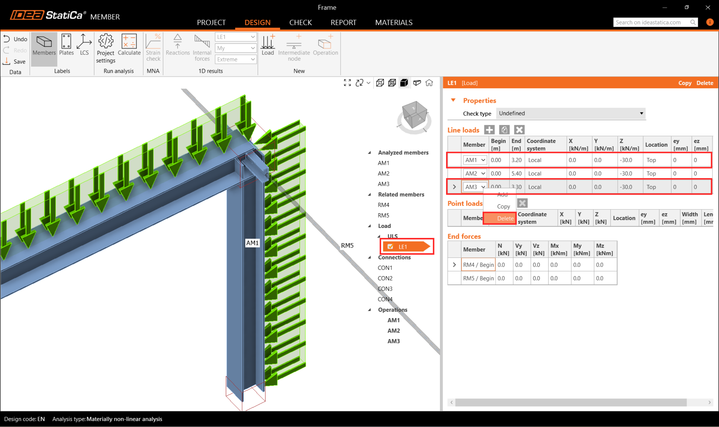
Apoi atribuiți o încărcare distribuită elementului AM2 și modificați intensitatea acesteia la -300 kN/m și lățimea la 300mm pentru a corespunde grinzii.
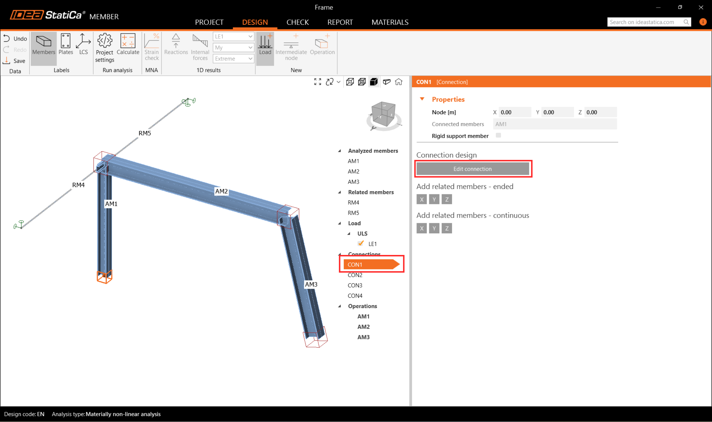
5 Îmbinări
În continuare, puteți proiecta nodurile. Selectați un cub de nod în scena 3D sau selectați un CON# din lista arborescentă și faceți clic pe Edit connection.
Începeți cu nodul CON1 la baza stâlpului din stânga. Modulul aplicației IDEA StatiCa Connection se deschide și puteți proiecta nodul selectând unul dintre șabloanele predefinite.
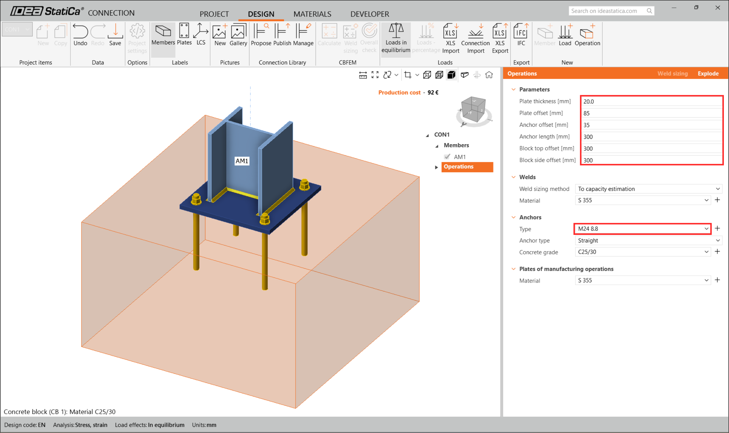
În acest caz, faceți clic pe butonul Propose din panglică și selectați primul șablon parametric.
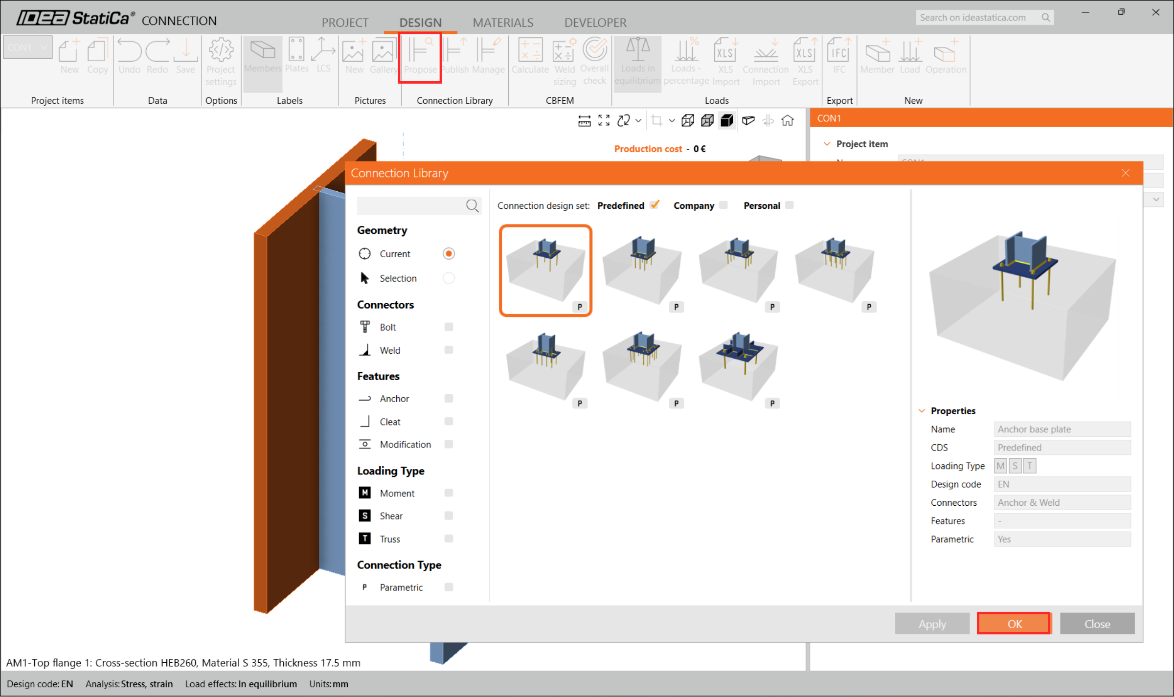
După aceea, configurați parametrii conform imaginii de mai jos și închideți aplicația Connection.
Apoi alegeți nodul CON2 și faceți clic pe 'Edit Connection' în modulul IDEA StatiCa Connection.

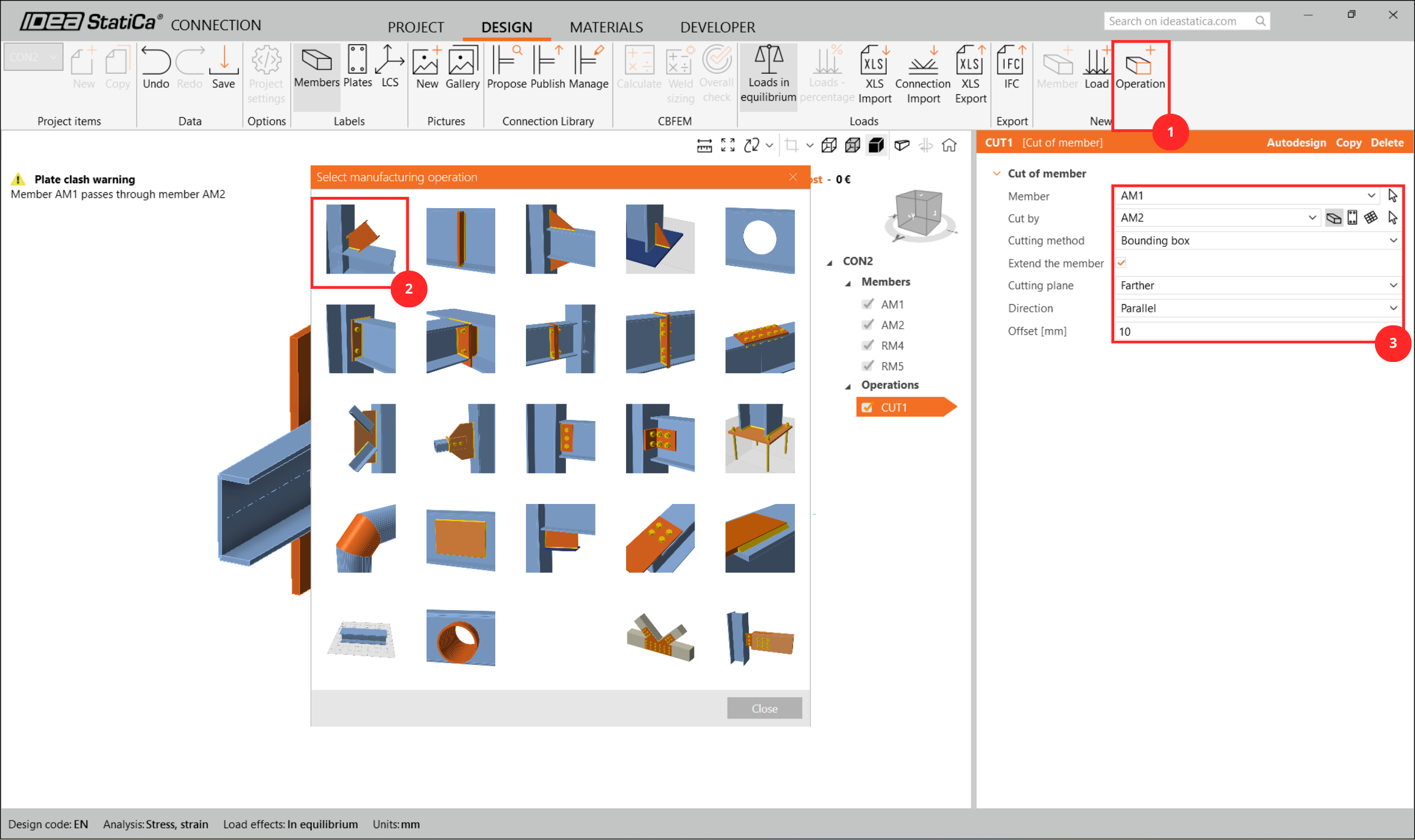
Pe baza capturilor de ecran de mai jos, definiți îmbinarea. Mai întâi, adăugați operația Cut.
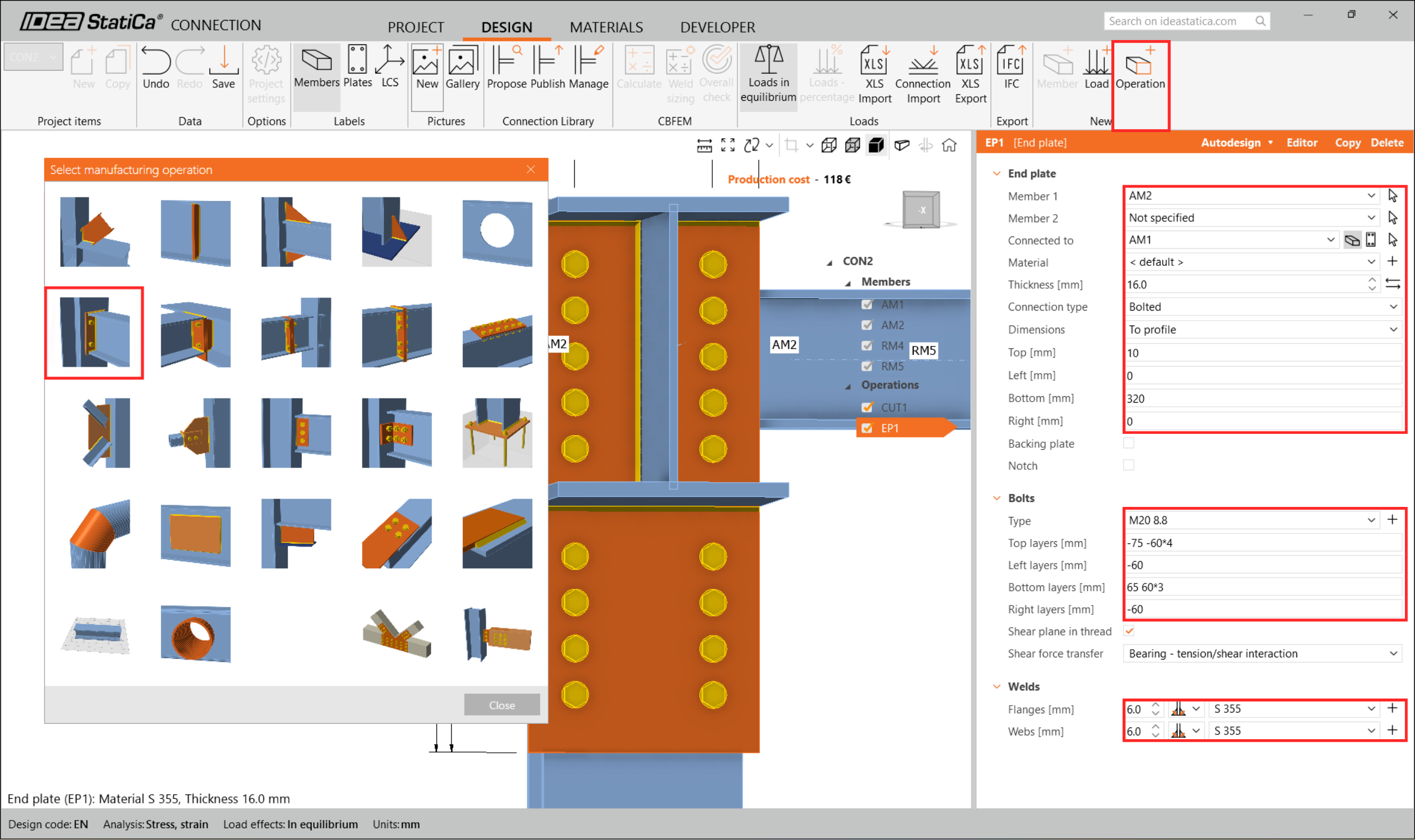
Apoi selectați End plate.
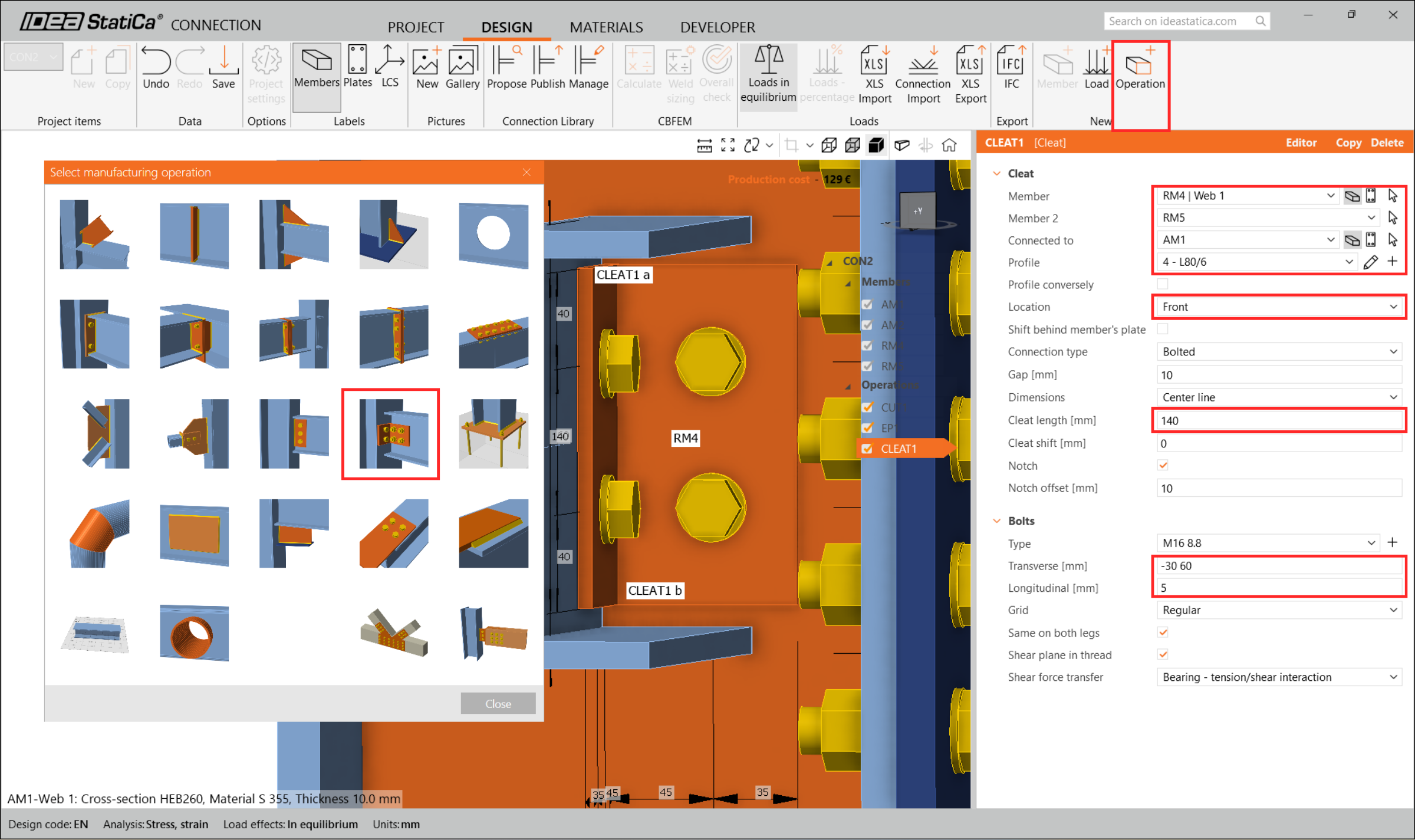
Definiți Cleats.
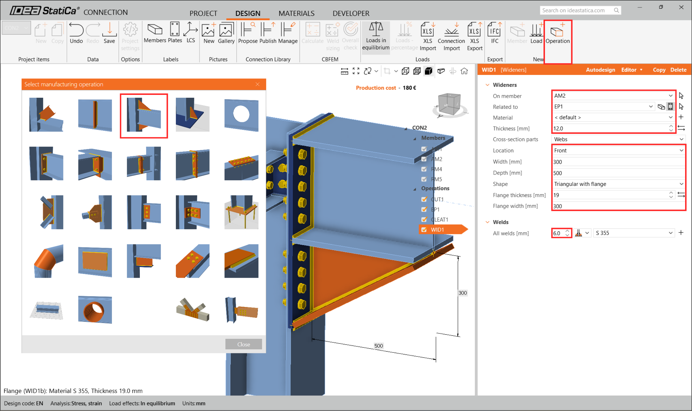
Adăugați Widener.
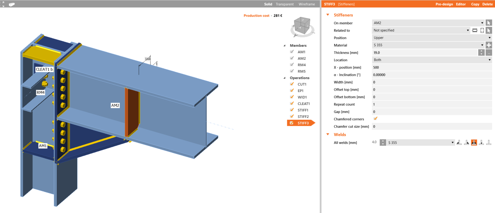
Definiți Stiffeners.
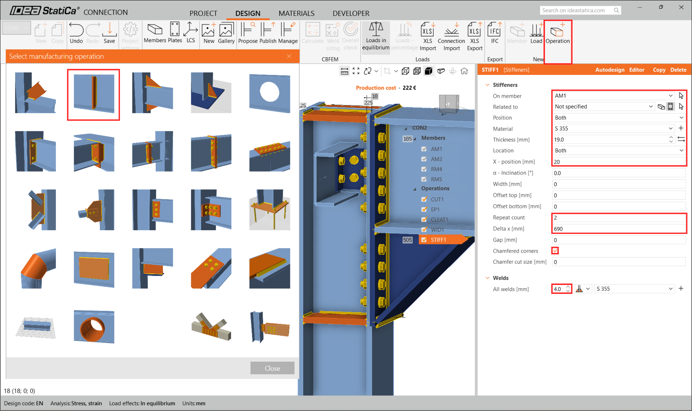
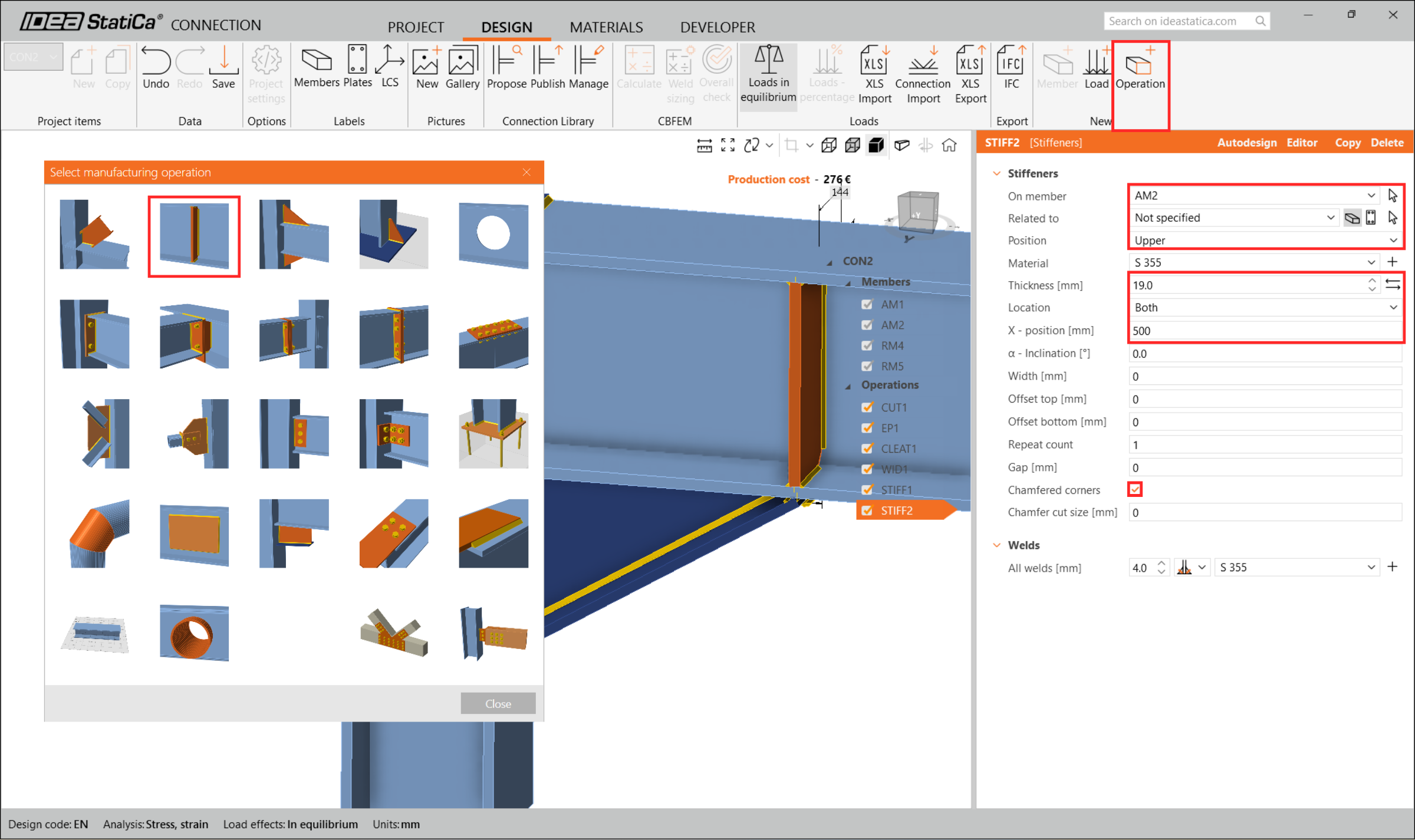
În consecință, îmbinarea dvs. ar trebui să arate ca în imaginea următoare.
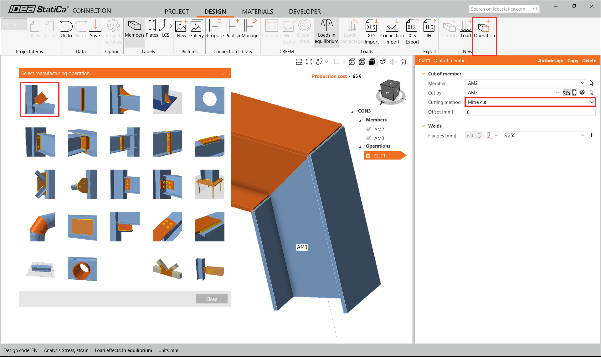
Continuați prin editarea nodului CON3.
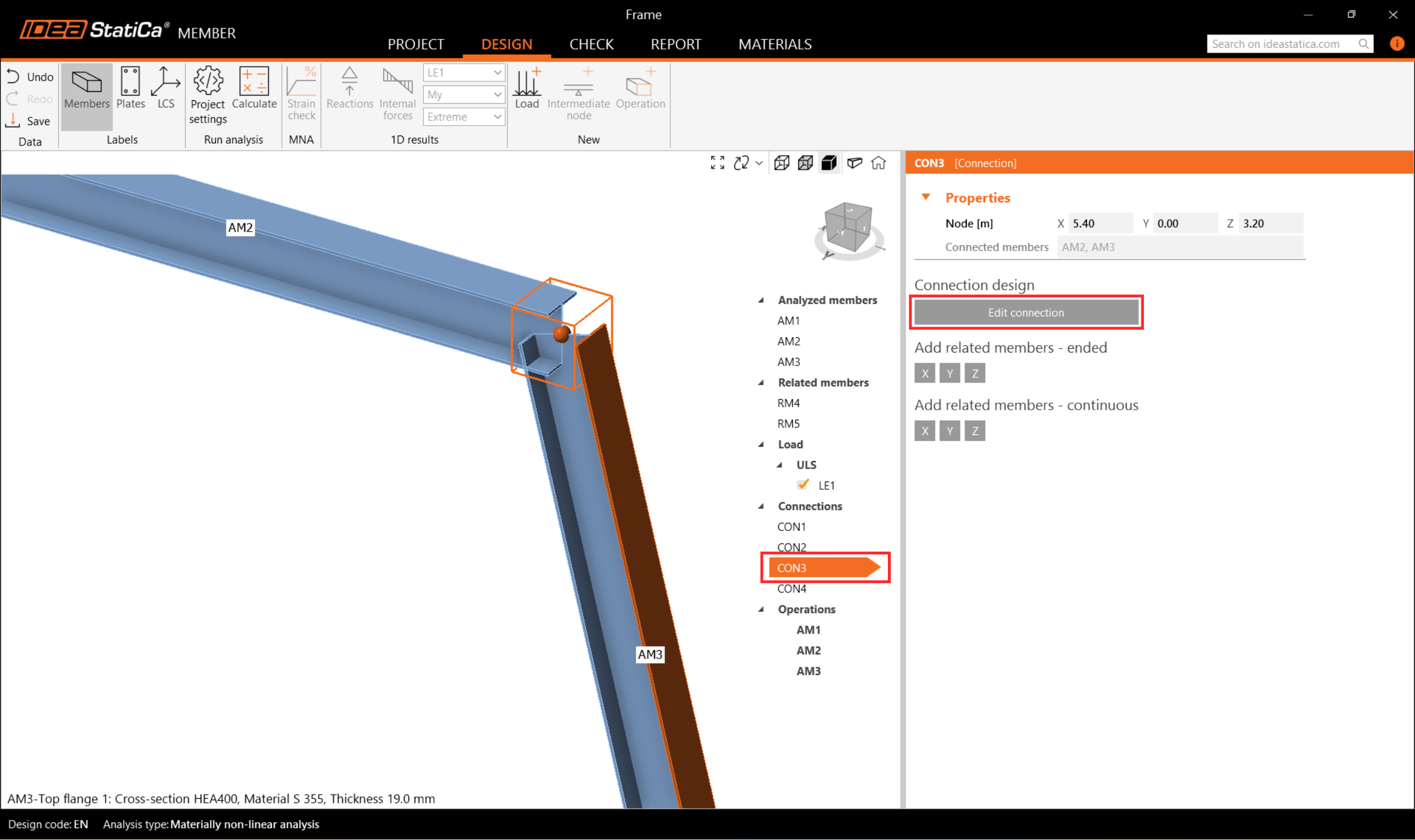
Aici, adăugați doar o operație Cut și setați metoda de tăiere la Mitre Cut pentru a crea o îmbinare rigidă.
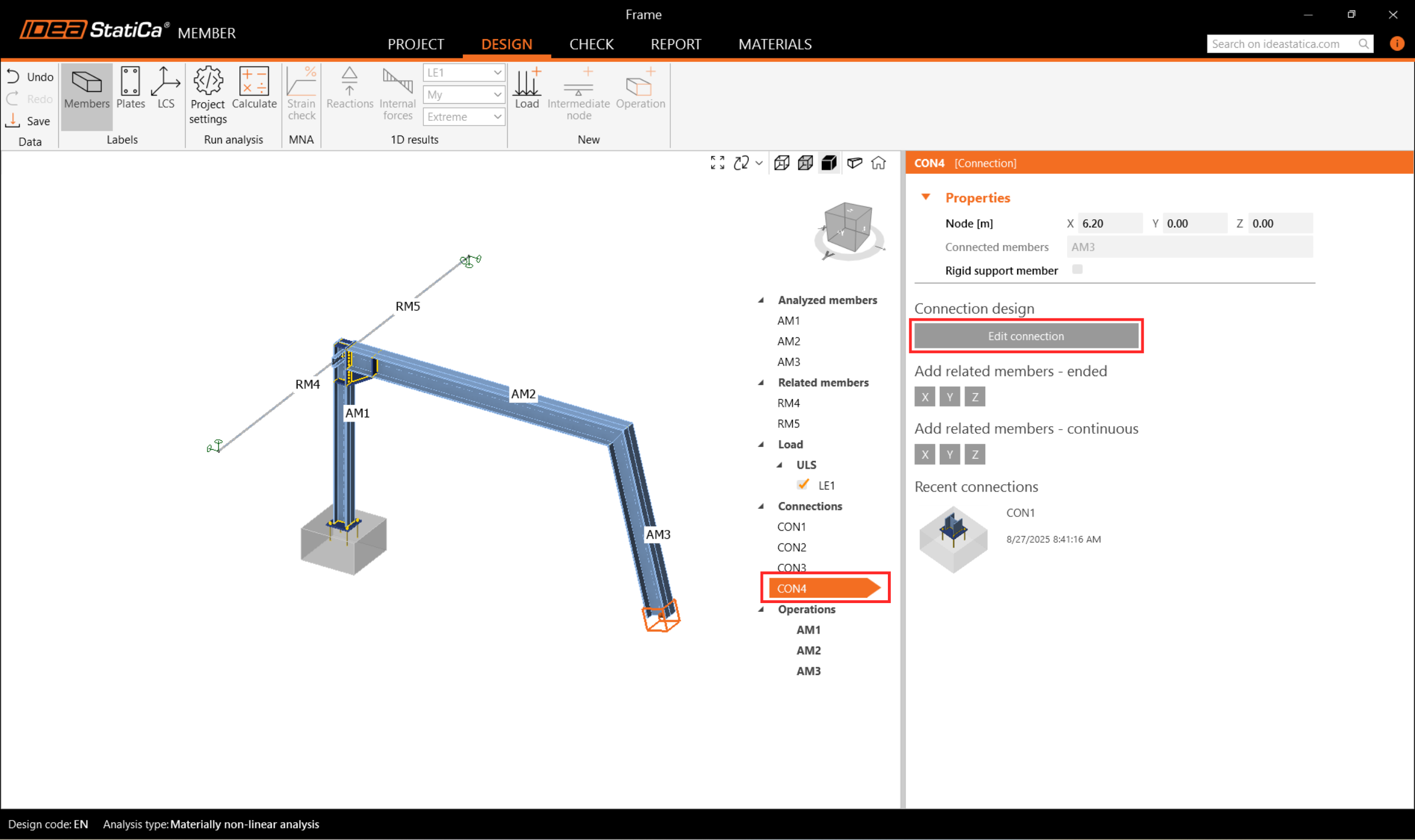
În final, editați nodul CON4. Chiar dacă software-ul ne oferă posibilitatea de a replica pur și simplu același design ca pentru CON1, vom edita îmbinarea pentru a crea una diferită.
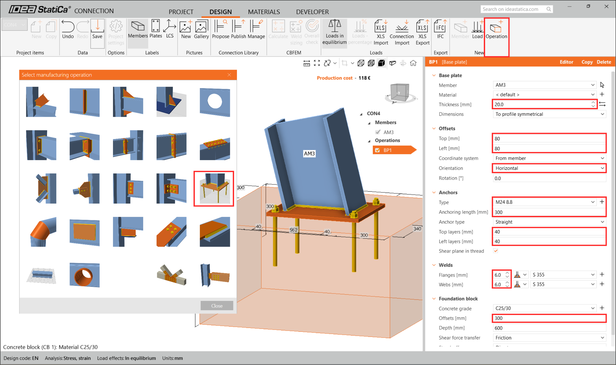
Adăugați operația Base plate și modificați parametrii conform imaginii următoare.
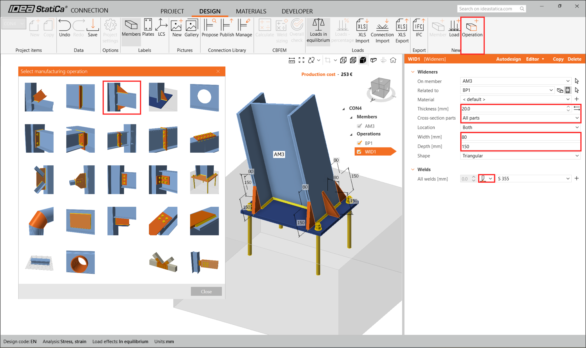
Adăugați Wideners la toate piesele.
6 Verificare
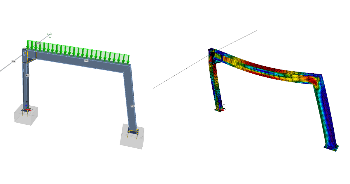
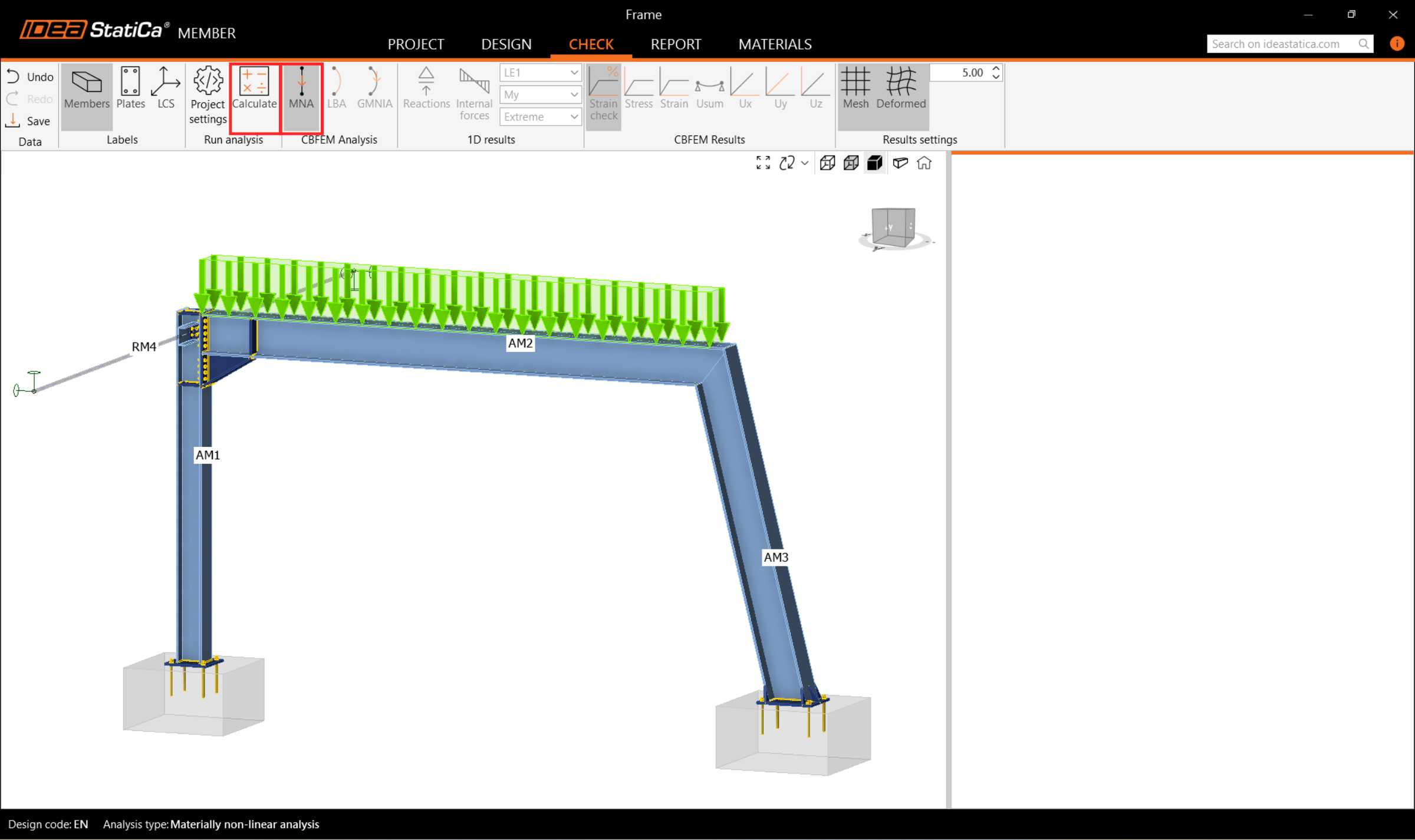
Să trecem la fila Check și să efectuăm analiza. Analiza în IDEA StatiCa Member este calculată în trei etape utilizând tehnologia CBFEM. Mai întâi, se analizează MNA (analiza materială neliniară) pentru a verifica capacitatea structurală, apoi se calculează LBA (analiza liniară de bifurcare) pentru a investiga stabilitatea structurală și, în final, se introduc imperfecțiunile inițiale pentru modurile de flambaj corespunzătoare și se calculează GMNIA (analiza geometrică și materială neliniară).
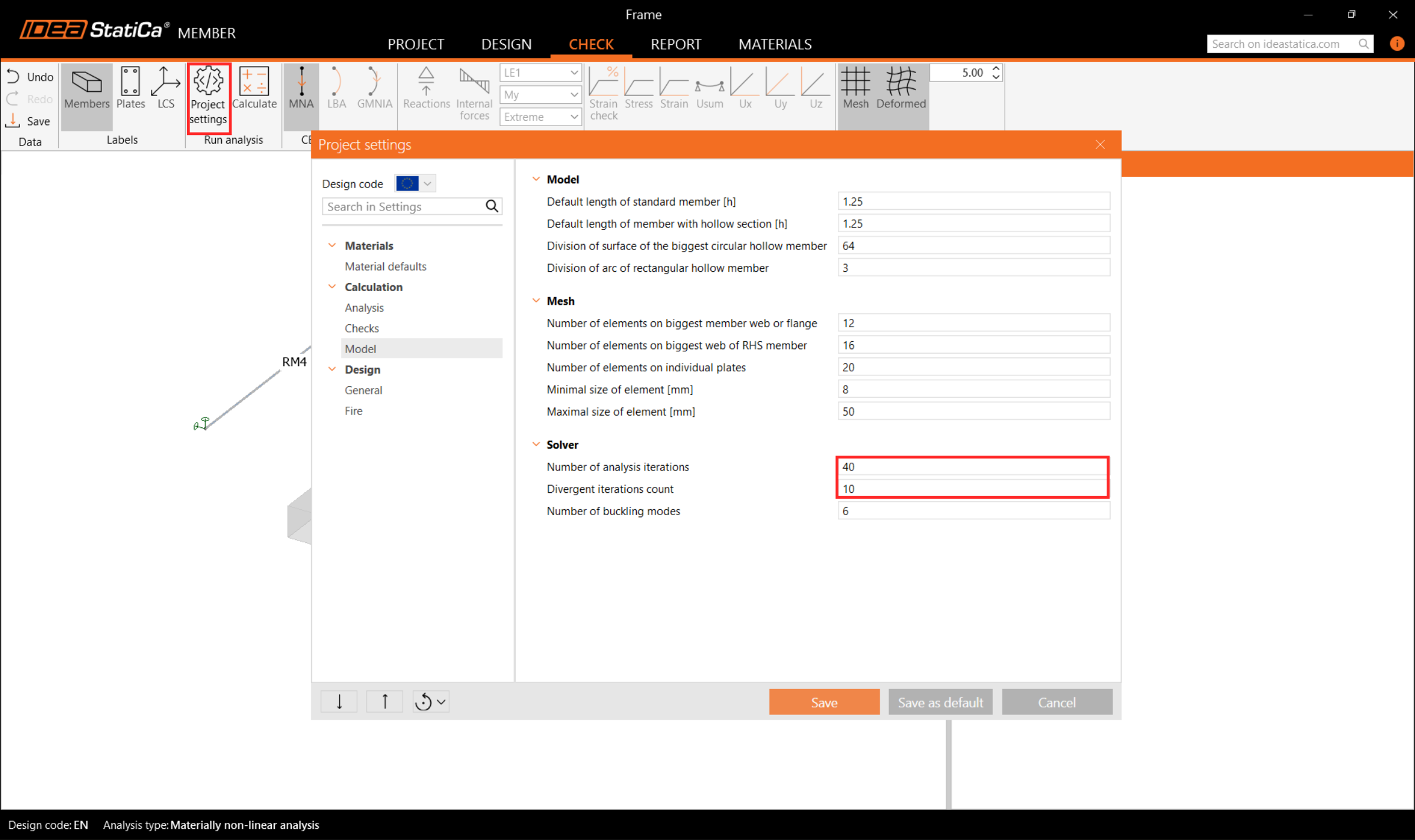
În primul rând, pentru acest proiect complex, trebuie să creșteți Number of analysis iterations la 40 și Divergent iterations count la 10 în Code setup pentru a asigura capacitatea de calcul necesară.
Apoi selectați analiza MNA și apăsați Calculate.
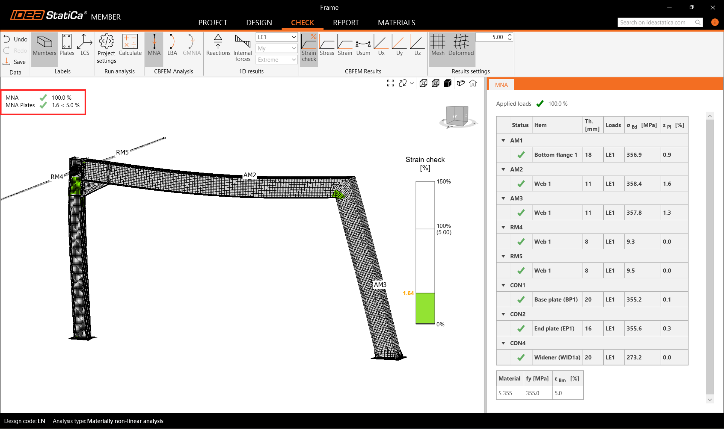
Rezultatele analizei MNA sunt afișate și puteți verifica starea fiecărei componente structurale, precum și rezultatele în fereastra 3D, de exemplu distribuția deformațiilor în partea analizată a structurii.
Apoi treceți la analiza LBA și repetați Calculul.
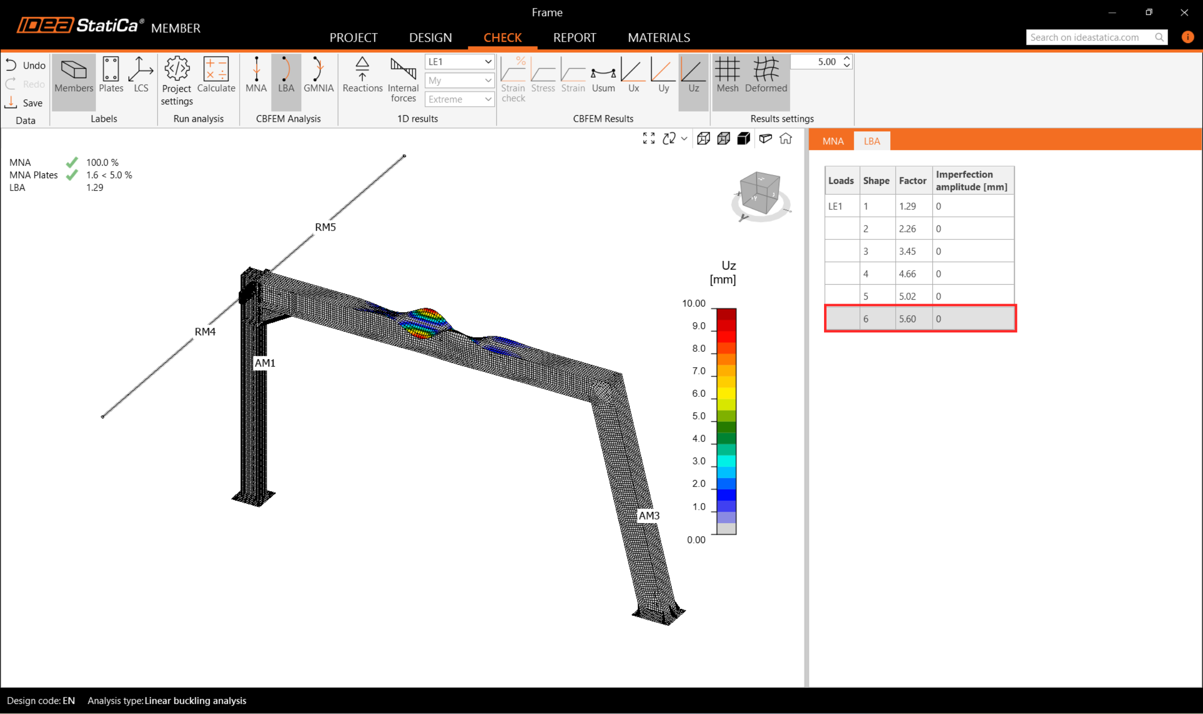
Puteți citi factorii modului de flambaj în filă și vizualiza primul mod de flambaj 1.
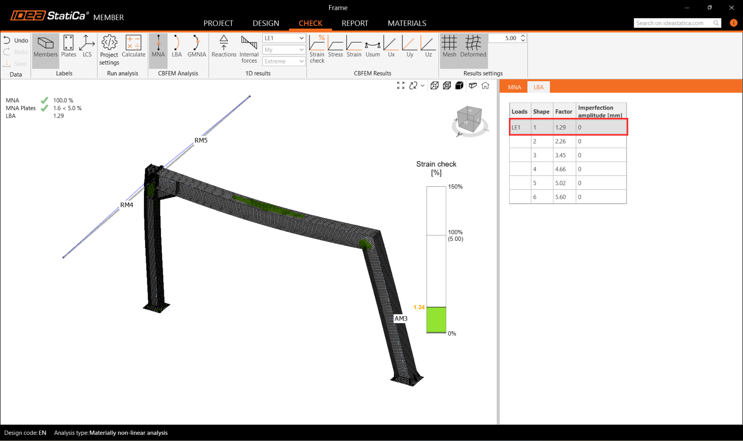
Puteți naviga prin vizualizarea celorlalte moduri de flambaj selectându-le în filă, de exemplu modul de flambaj 6.
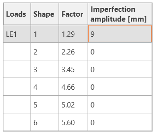
Deoarece cel puțin unul dintre factorii modului de flambaj este mai mic decât 15, treceți la GMNIA pentru a efectua analiza neliniară a stabilității structurale. Conform EN 1993-1-1, alegeți cel mai critic mod de flambaj sau o combinație de moduri de flambaj și introduceți imperfecțiunea inițială a grinzii critice. În acest caz, alegeți primul mod de flambaj 1 ca fiind cel mai critic. Treceți la fila GMNIA din panoul din dreapta și determinați imperfecțiunea de 9 mm (0,5xL/300 = 0,5*5400/300 = 9 mm), pe care o introduceți ca Amplitudine în coloana 1.
Apoi faceți din nou clic pe butonul Calculate. În acest caz, analiza poate dura câteva minute.
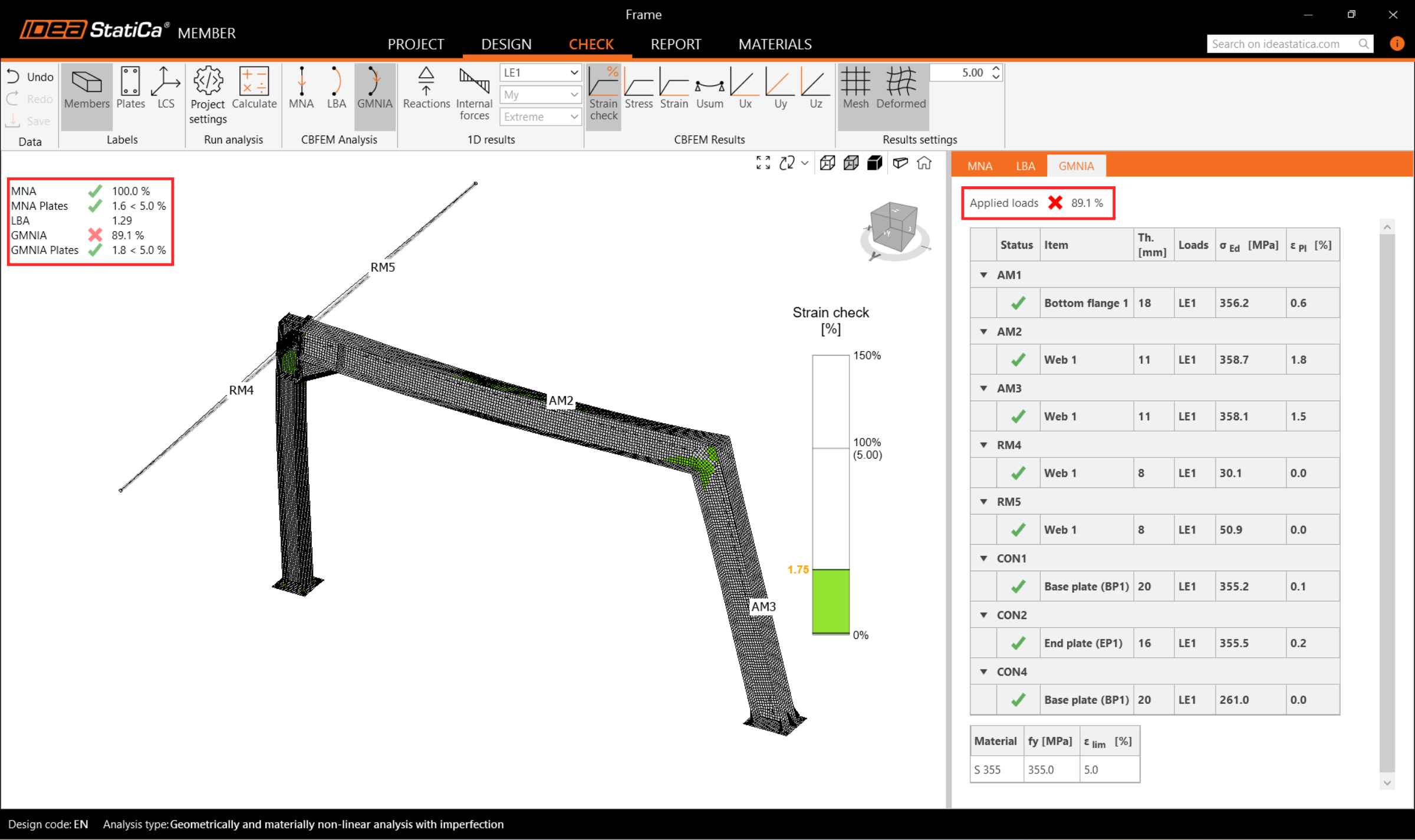
Pe măsură ce navigați prin rezultate, puteți observa că încărcările aplicate în GMNIA nu au atins 100%, ceea ce înseamnă că sub încărcările date, structura își pierde stabilitatea. Pentru a trece verificările de stabilitate, trebuie să consolidați cadrul.
7 Operații
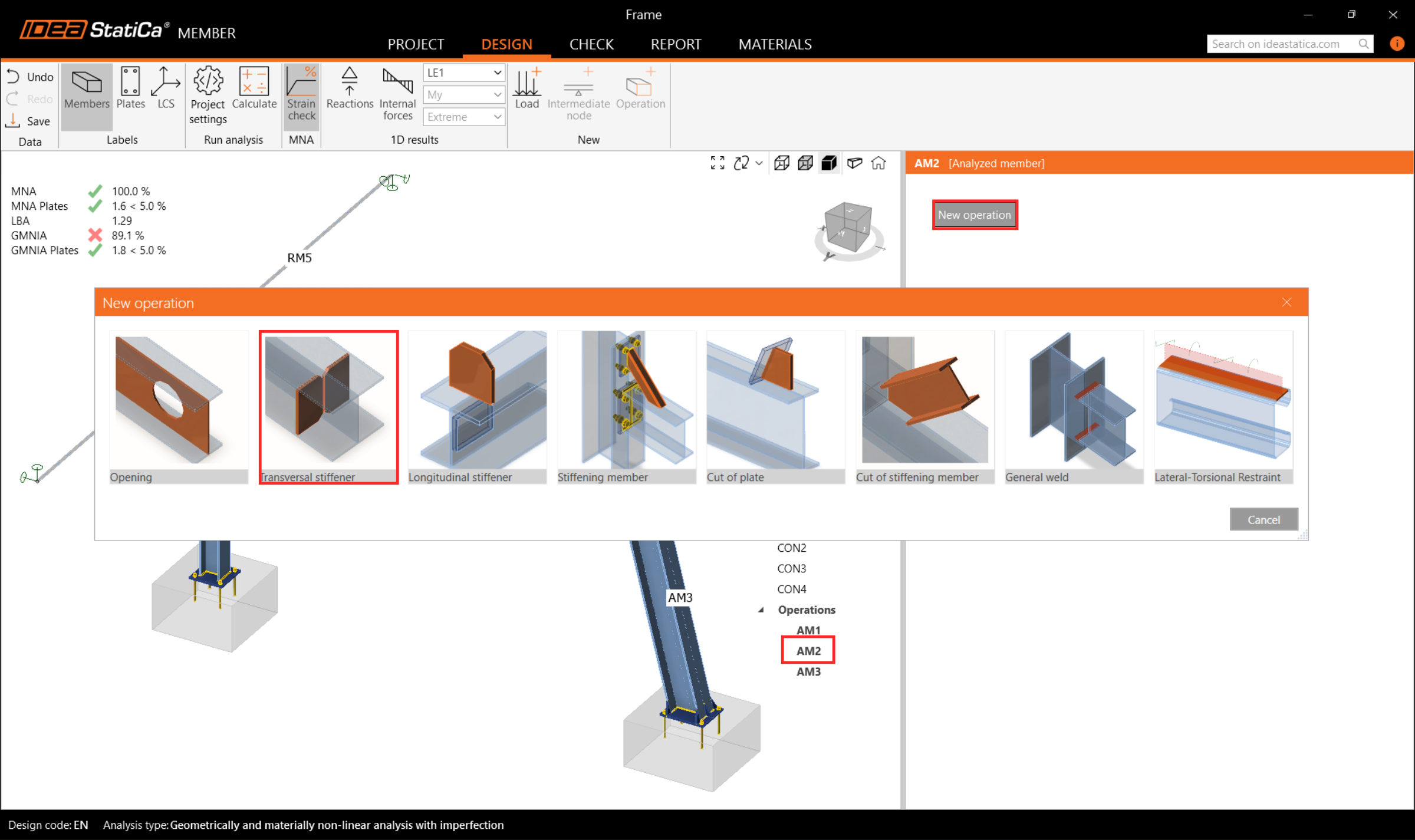
Reveniți la fila Design și în meniul arborescent, navigați la Operations, faceți clic dreapta pe AM2, și adăugați elemente de rigidizare Transversale pentru a consolida colțul cadrului cel mai solicitat și a reduce efectele de flambaj.
În operația STIFF T1, setați grosimea la 20mm și poziția X la 5200 mm conform imaginii următoare.

Apoi modificați parametrii elementului de rigidizare și adăugați încă un element de rigidizare transversal la aceeași grindă AM2 și unul la stâlpul AM3 și poziționați-le corect.
Copiați operația STIFF T1 și setați noile proprietăți conform imaginii de mai jos.
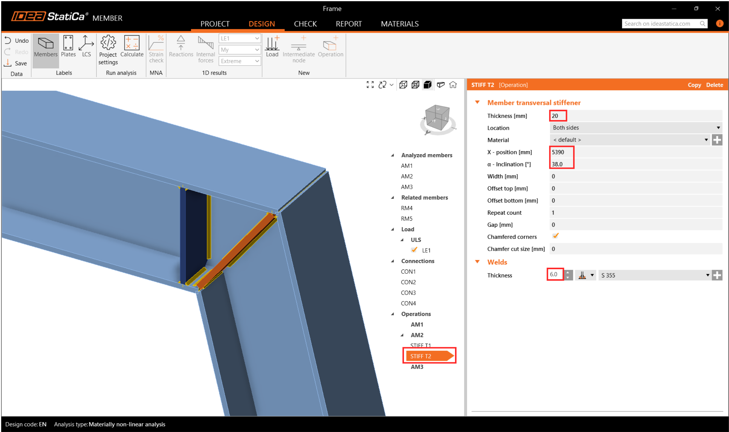
Creați o nouă operație de rigidizare pentru AM3 și setați proprietățile conform imaginii următoare.

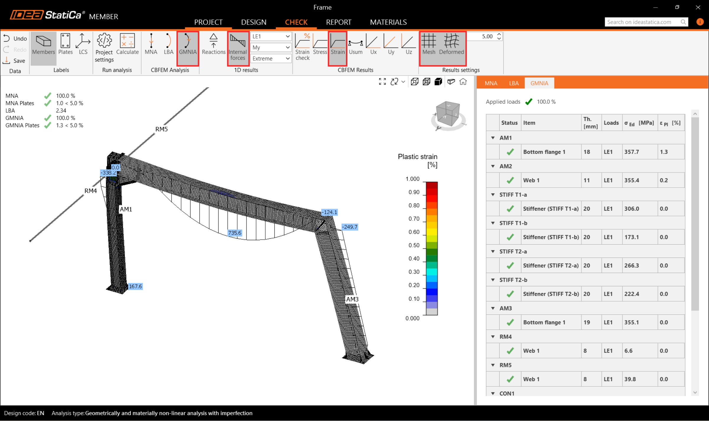
Acum reveniți la fila Check și repetați calculul în trei etape - MNA, LBA, GMNIA. Cadrul proiectat a trecut verificările conform codului privind stabilitatea cu imperfecțiunile inițiale aplicate și puteți naviga prin rezultate, cum ar fi distribuția deformațiilor și diagrama forțelor interioare.
8 Raport
În final, accesați fila Report. IDEA StatiCa oferă un raport complet personalizabil, care poate fi tipărit sau salvat într-un format editabil.
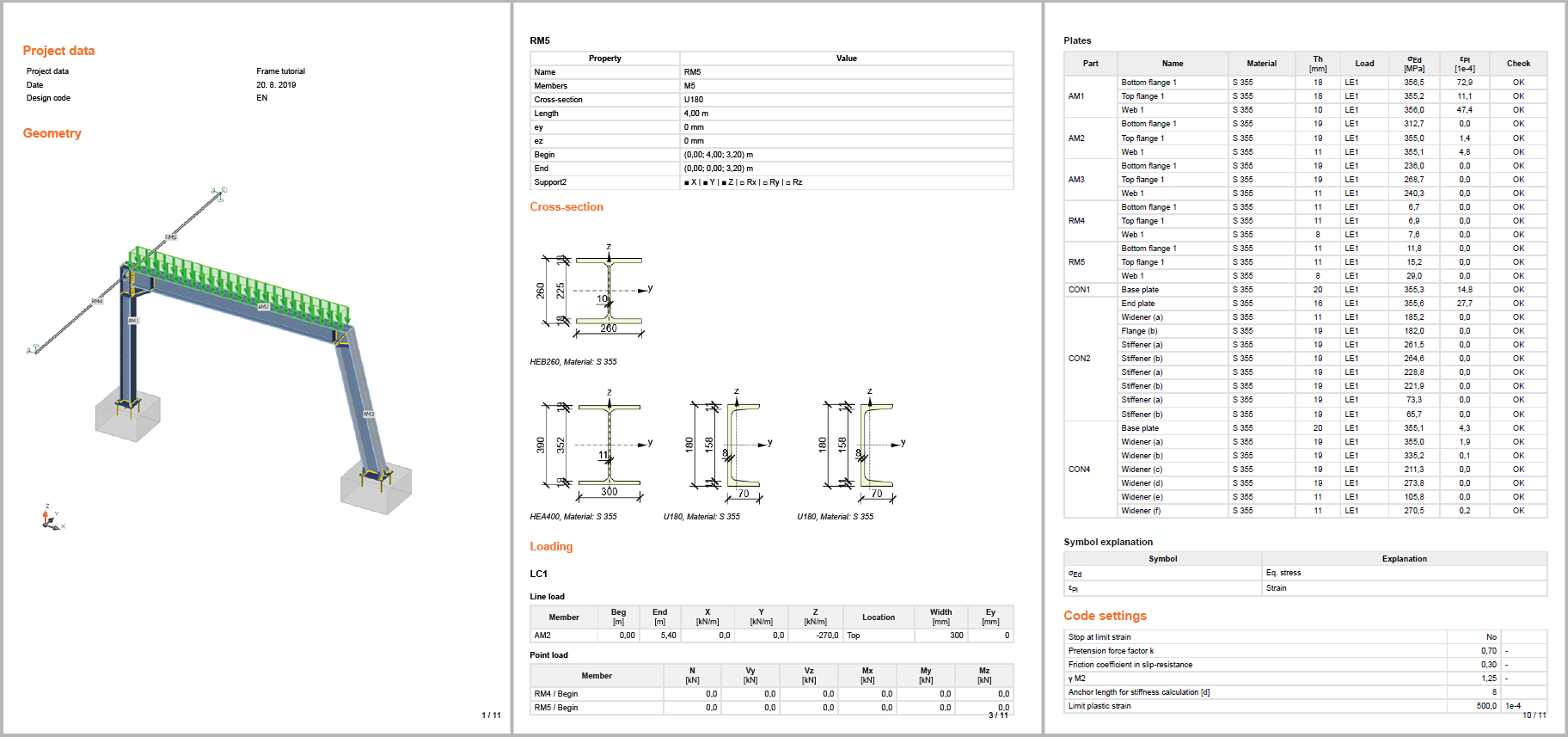
Ați proiectat, optimizat și verificat conform codului un cadru metalic ca detaliu structural conform Eurocodului (EN).