Autodesk Robot Structural Analysis Professional BIM-Verknüpfung für die Bemessung von Stahlbauteilen (EN)
So aktivieren Sie den Link
- Downloaden und installieren Sie (als Administrator) die aktuelle Version von IDEA StatiCa
- Vergewissern Sie sich, dass Sie die unterstützte Version verwenden
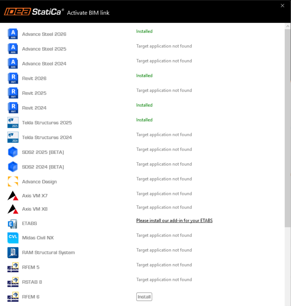
IDEA StatiCa integriert den BIM-Link während der Installation automatisch in Ihre FEA-/BIM-Lösung. Sie können den Status überprüfen und weitere BIM-Links für nachträglich installierte Software im BIM-Link-Installer aktivieren.
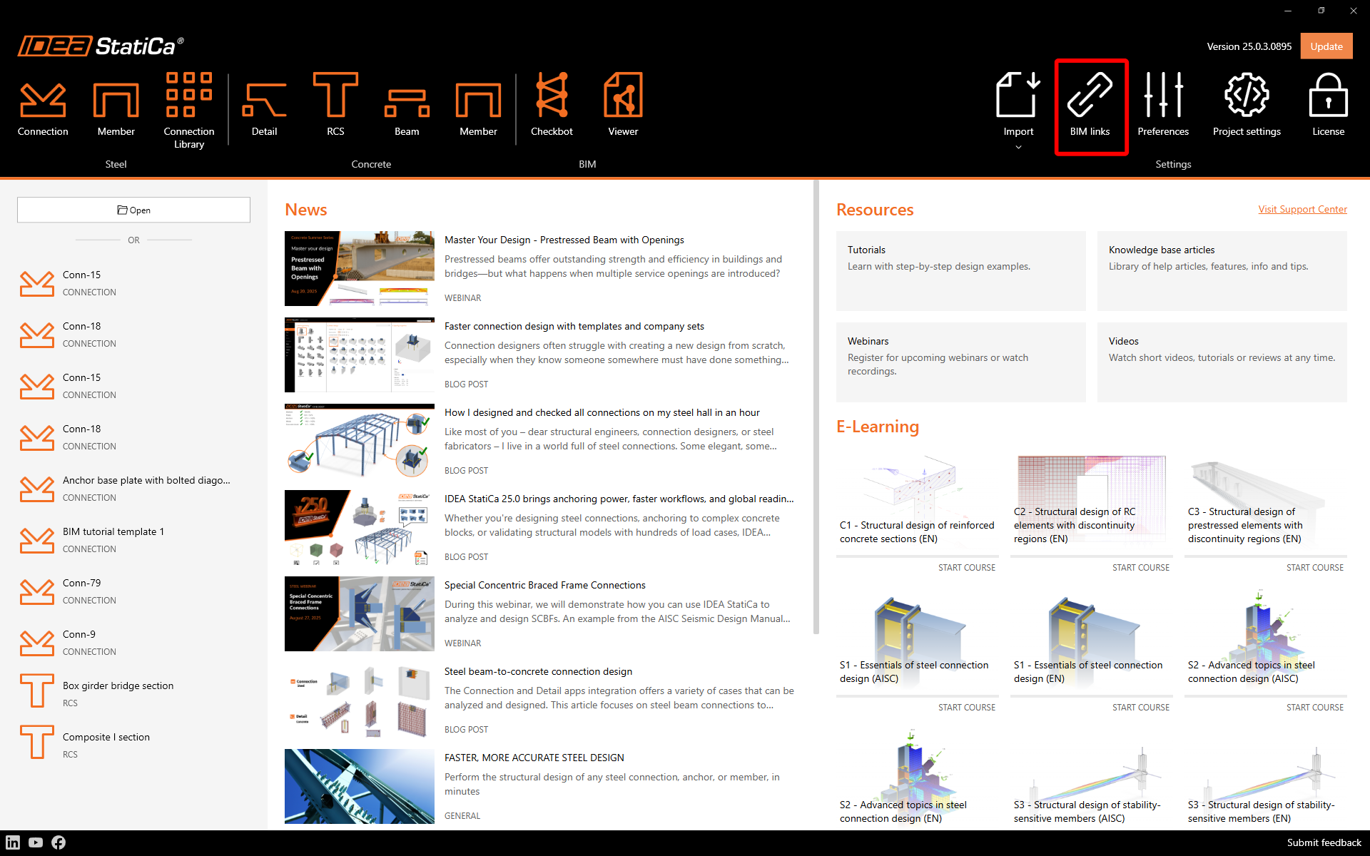
Öffnen Sie IDEA StatiCa und navigieren Sie zum Bereich BIM und öffnen Sie den BIM Link Installer. Eventuell erscheint eine Meldung Als Administrator ausführen, bitte bestätigen Sie mit Ja.
Bitte beachten Sie, dass einige FEA-Lösungen zusätzliche Schritte erfordern, um ihre BIM-Verbindung zu IDEA StatiCa vollständig zu aktivieren.
Öffnen Sie IDEA StatiCa und navigieren Sie zum Tab BIM und öffnen Sie den BIM-Link-Installer (Aktivieren deinen BIM-Link...).
Eine Benachrichtigung "Möchten Sie zulassen, dass diese Anwendung Änderungen an Ihrem Gerät vornimmt?" erscheinen, wenn ja, bestätigen Sie dies bitte mit Ja.
Der BIM-Link für die ausgewählte Software (falls gefunden) wird installiert. Der Bildschirm informiert Sie auch über den Status anderer BIM-Links, die möglicherweise bereits installiert wurden.
Verwendung der Verknüpfung
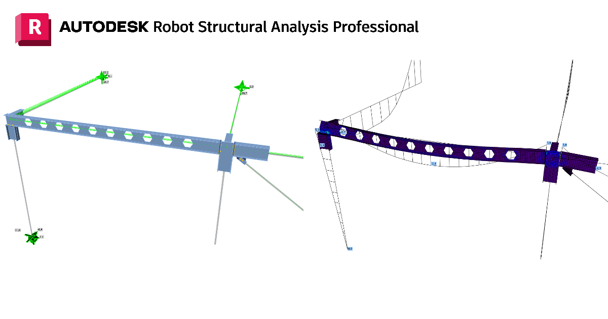
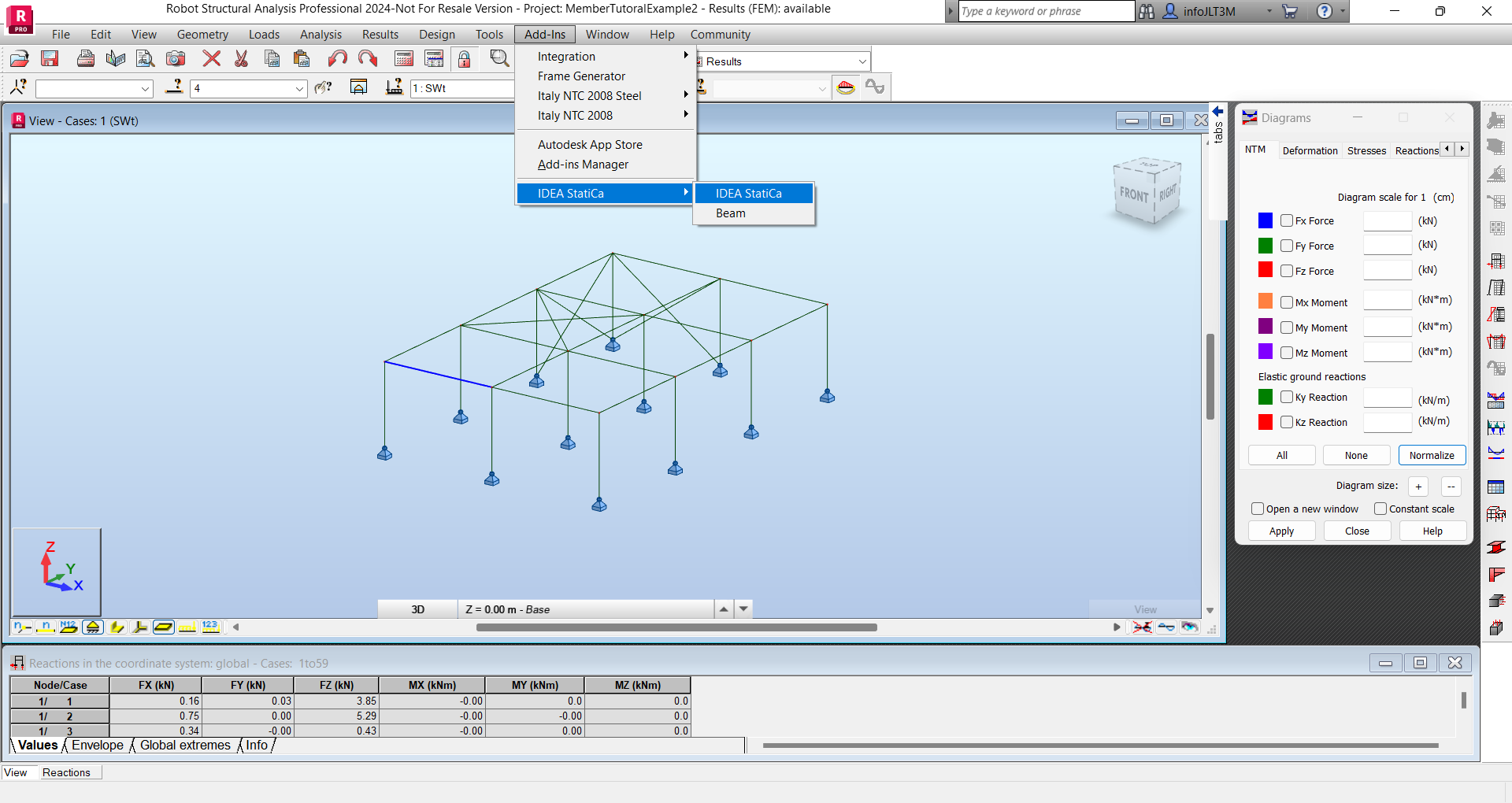
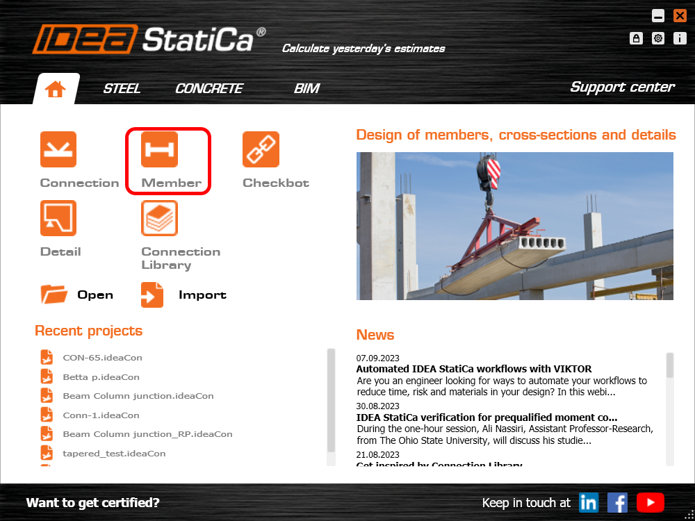
Öffnen Sie zunächst die Quelldatei ARSAP-Member-Tutorial.rtd aus den bereitgestellten Dateien zum Herunterladen (am Ende dieses Tutorials). Navigieren Sie dort zum Menü Add-ins, dann zu IDEA StatiCa und starten Sie IDEA StatiCa. Dadurch wird Checkbot gestartet.
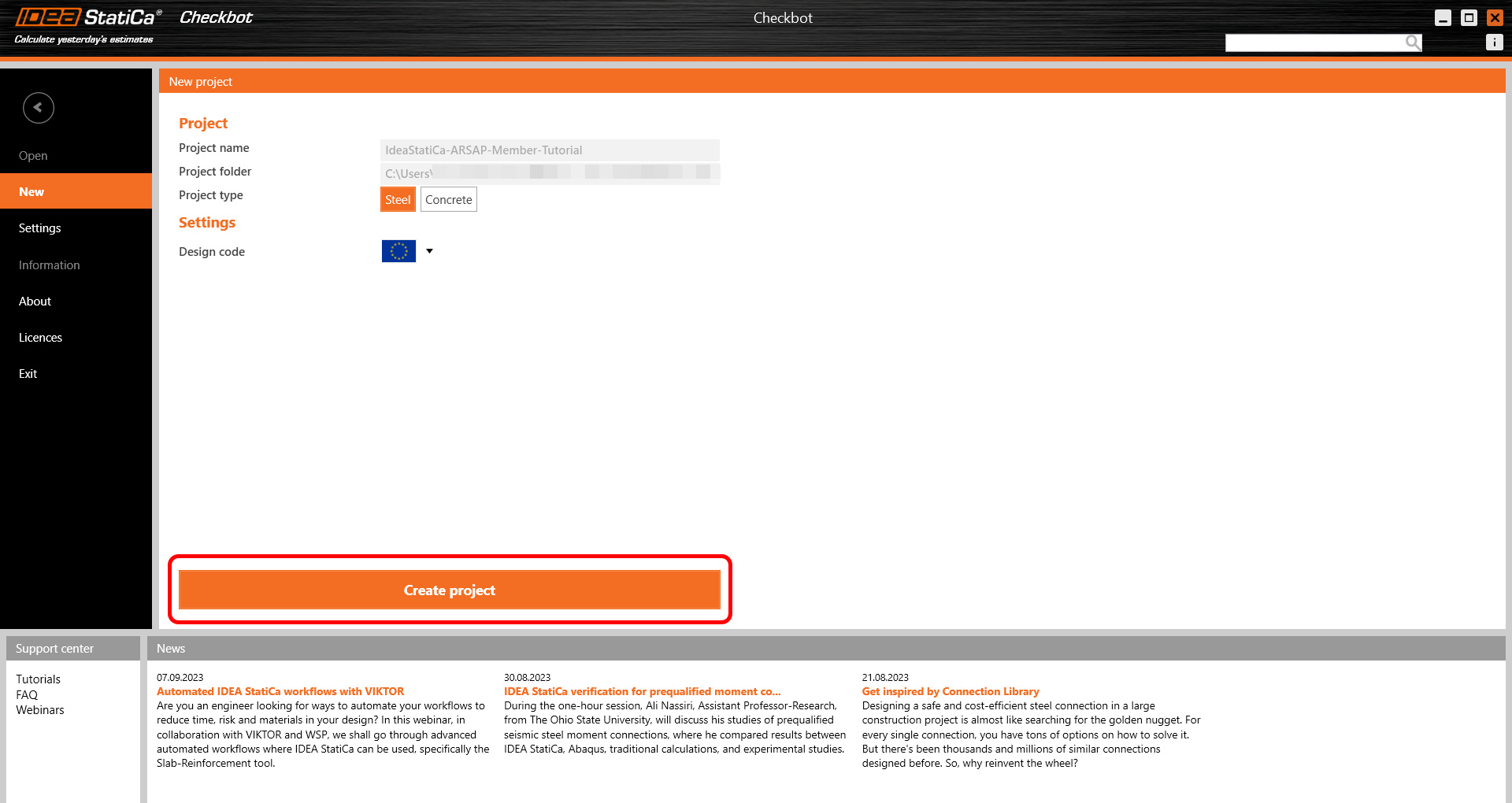
Sie werden aufgefordert, ein neues Projekt zu erstellen.
Checkbot öffnet sich und Sie können den Importvorgang starten. Wählen Sie den angegebenen Träger im Robot-Modell aus und klicken Sie auf Member, um ihn für die Analyse in IDEA StatiCa Member gemäß EN-Norm zu importieren.
Das Bauteil wird zusammen mit den zugehörigen Verbindungen, verwandten Bauteilen und Lastkombinationen zur Liste hinzugefügt, ohne dass diese manuell eingegeben werden müssen. Belassen Sie die Standardeinstellungen und beginnen Sie zunächst mit der Konfiguration der Verbindungen.
Die Verwendung der BIM-Verknüpfung auf diese Weise ermöglicht es Ihnen, nicht nur die Bauteile, sondern auch die Verbindungen zu bemessen. Zur Erinnerung: In der Member-Anwendung können Verbindungen nicht bemessen, sondern nur modelliert werden. In Checkbot können Verbindungen mithilfe der Lastkombinationen aus der FEA-Anwendung modelliert und bemessen werden. Diese resultierenden Verbindungen können dann bei der Bemessung des Bauteils wiederverwendet werden. Dadurch werden Verbindungen effizienter bemessen.
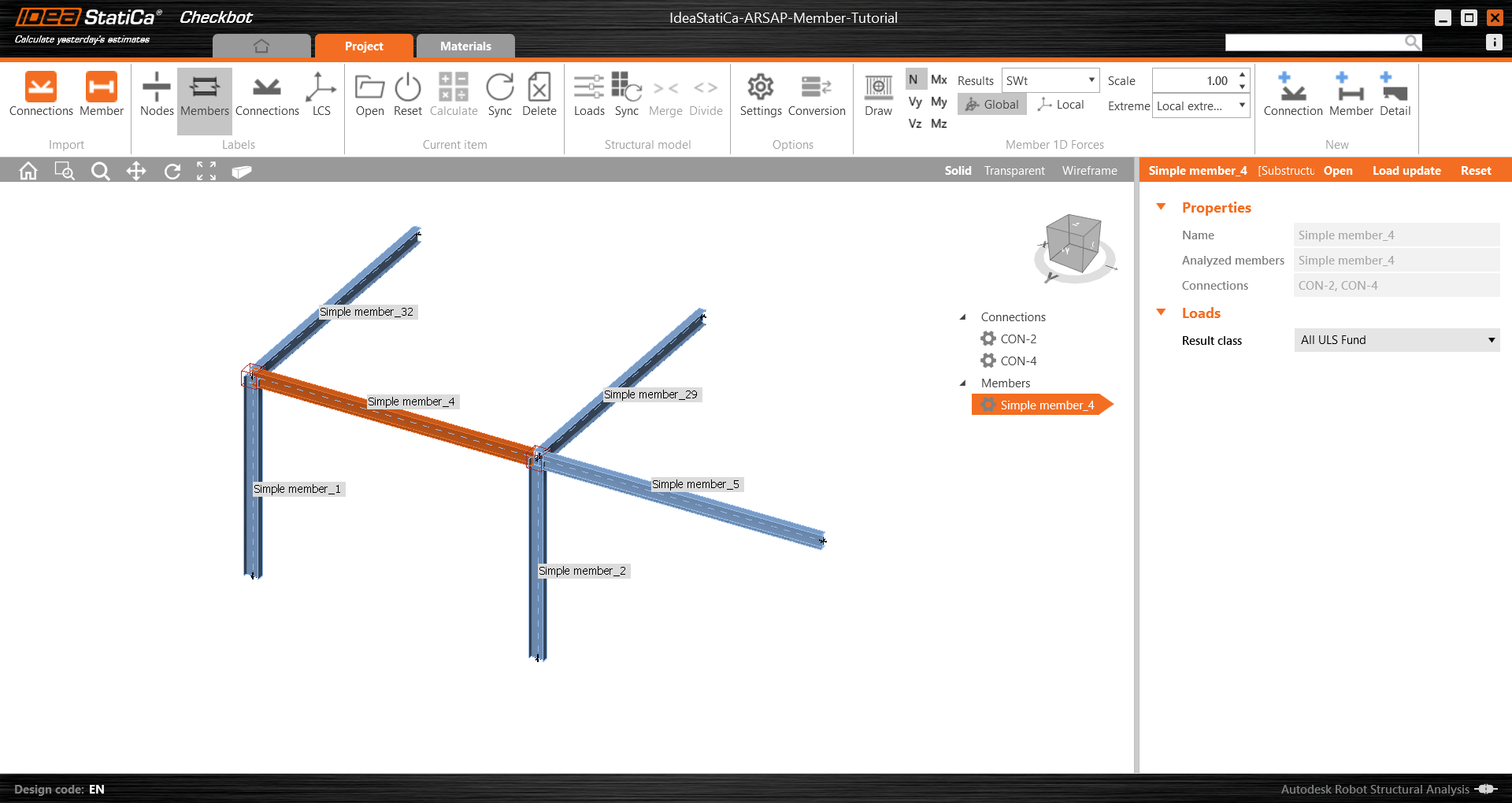
Öffnen Sie Simple member_4, um die vollständige Liste der Bauteile, Verbindungen und Lastkombinationen anzuzeigen.
Bemessung
Es gibt zwei Möglichkeiten, das Bauteil und seine Verbindungen zu bemessen:
- Online – direkt in Checkbot mit aktiver Verknüpfung zur FEA-Anwendung
- Offline – ebenfalls in Checkbot, jedoch unter Verwendung der Daten aus der FEA-Anwendung
Der Einfachheit halber (und um denjenigen ohne Autodesk Robot Structural Analysis Professional zu helfen) wechseln wir nun zu einem Offline-Ansatz. Der Projektordner kann auch über den Link am Ende dieses Tutorials heruntergeladen und entpackt werden.
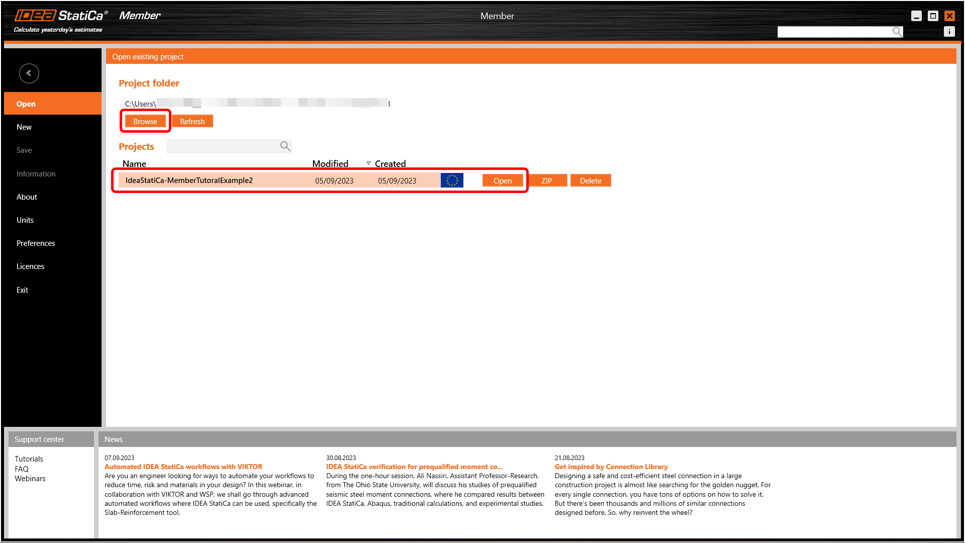
Sie können Checkbot und Robot beenden und das Projekt dann in Member öffnen, indem Sie danach suchen.
Dadurch wird die Member-Anwendung im sogenannten Offline-Modus geöffnet – dies lässt sich daran erkennen, dass in der Informationsleiste am unteren Bildschirmrand keine Anwendung angezeigt wird.
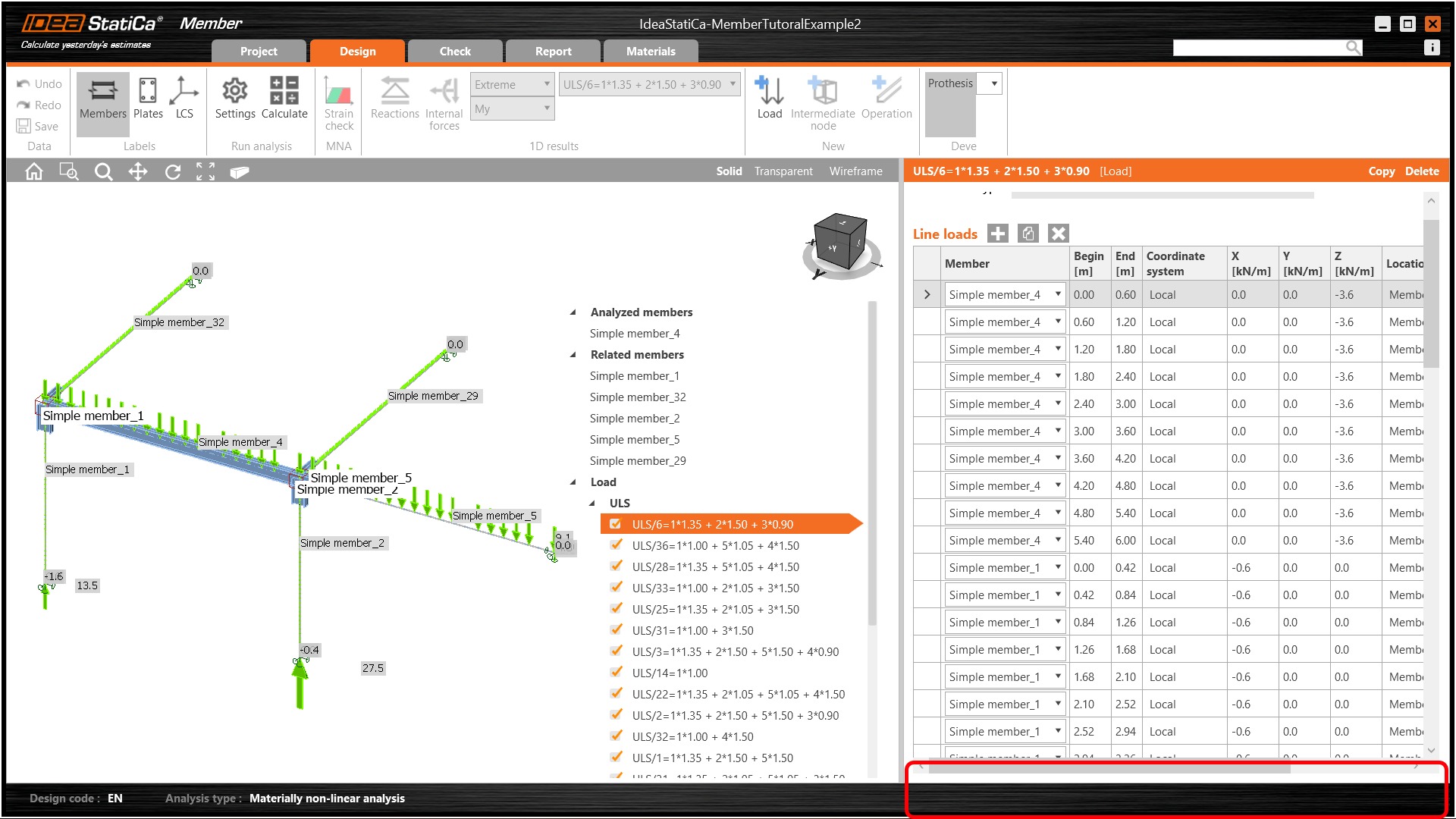
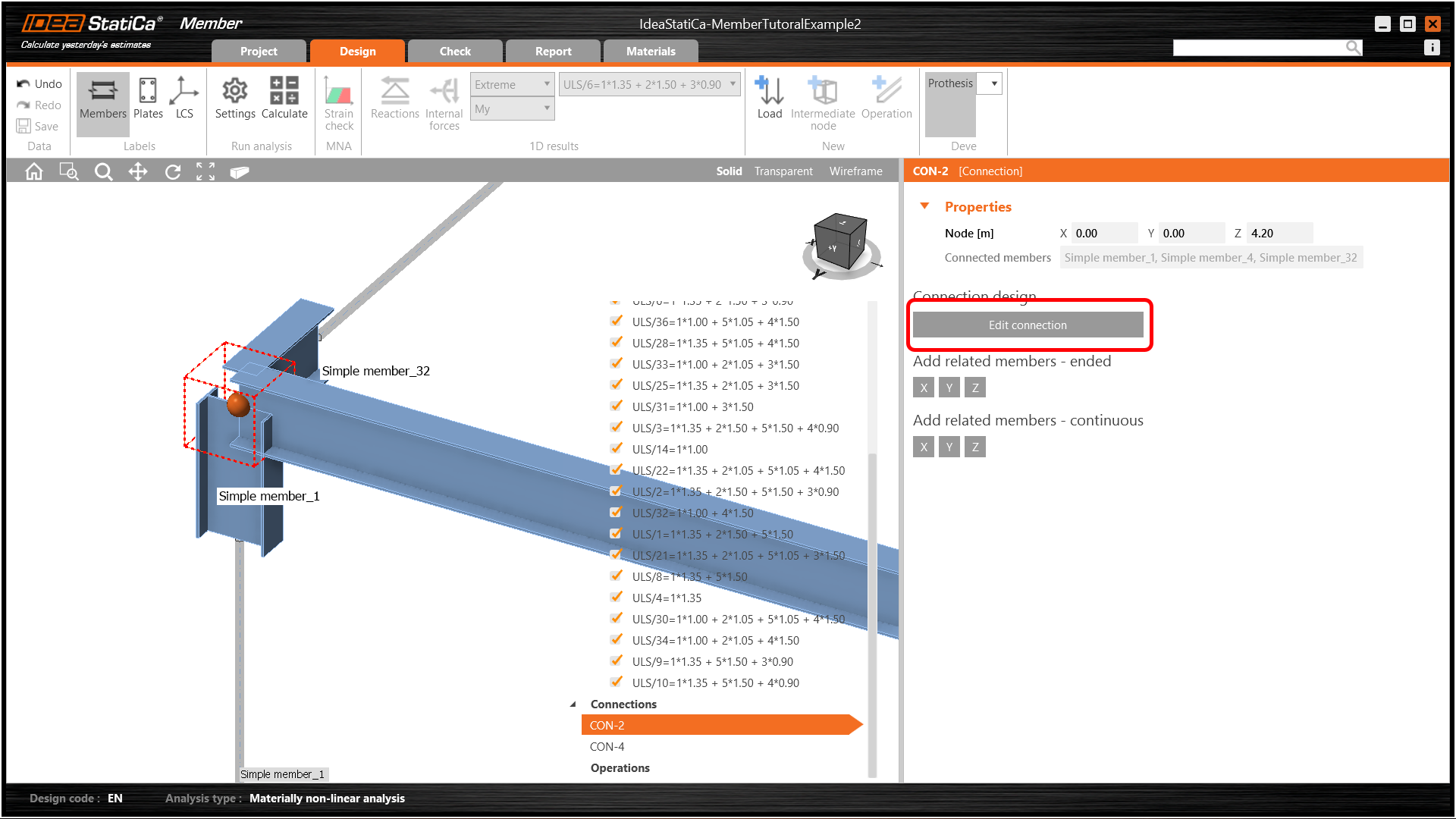
Wir können nun fortfahren, indem wir CON-2 auswählen und auf Verbindung bearbeiten klicken.
Dadurch wird die bekannte IDEA StatiCa Connection-Anwendung geöffnet. Wenden Sie eine Schnitt-Bauteil-Operation auf die Stütze an, um deren Höhe um 20 mm über den Obergurt des Trägers hinaus zu verlängern.
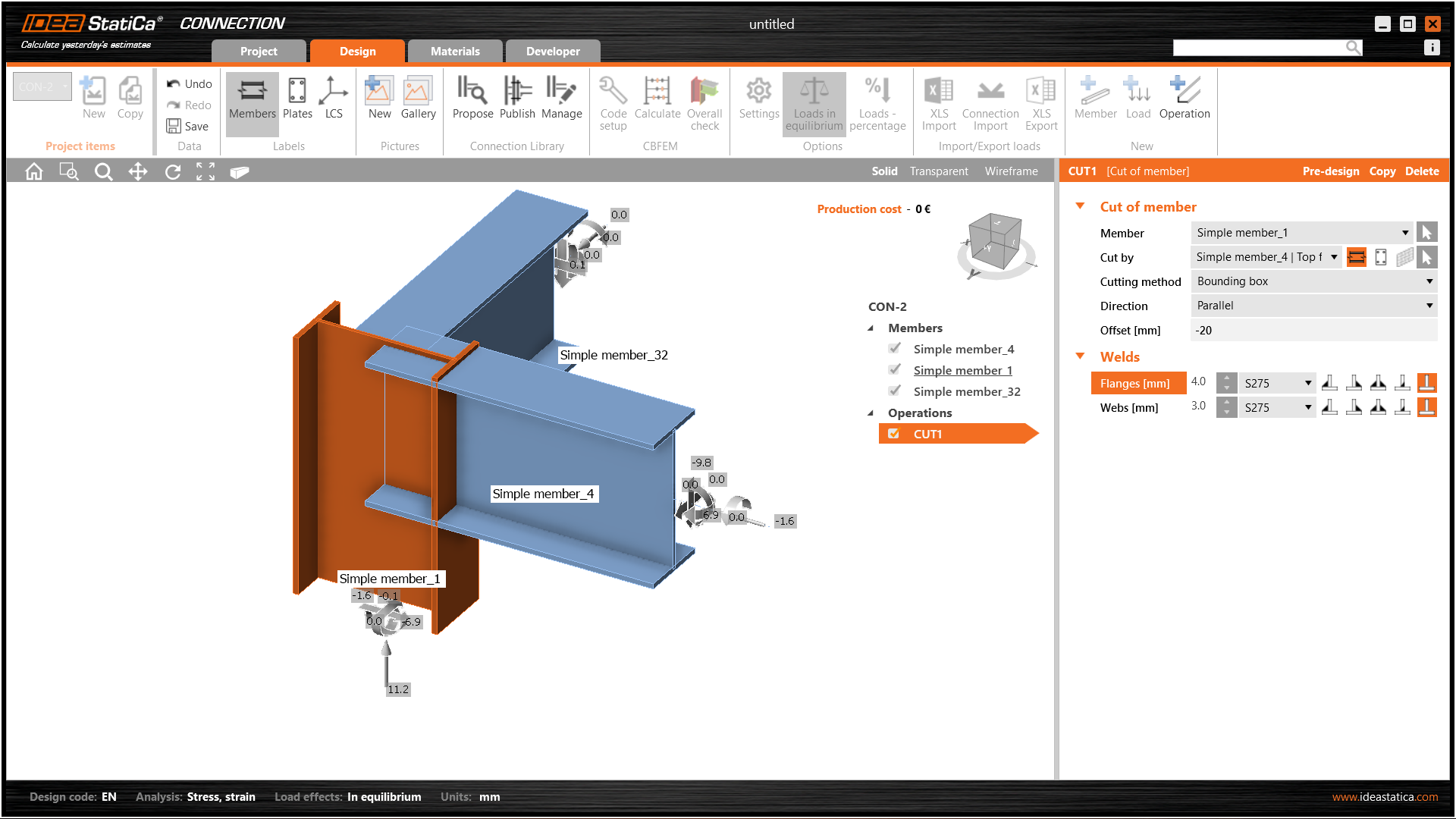
Fügen Sie anschließend beiden Trägern eine einfache Stirnplatte hinzu – denken Sie daran, dass Sie Operationen kopieren können.
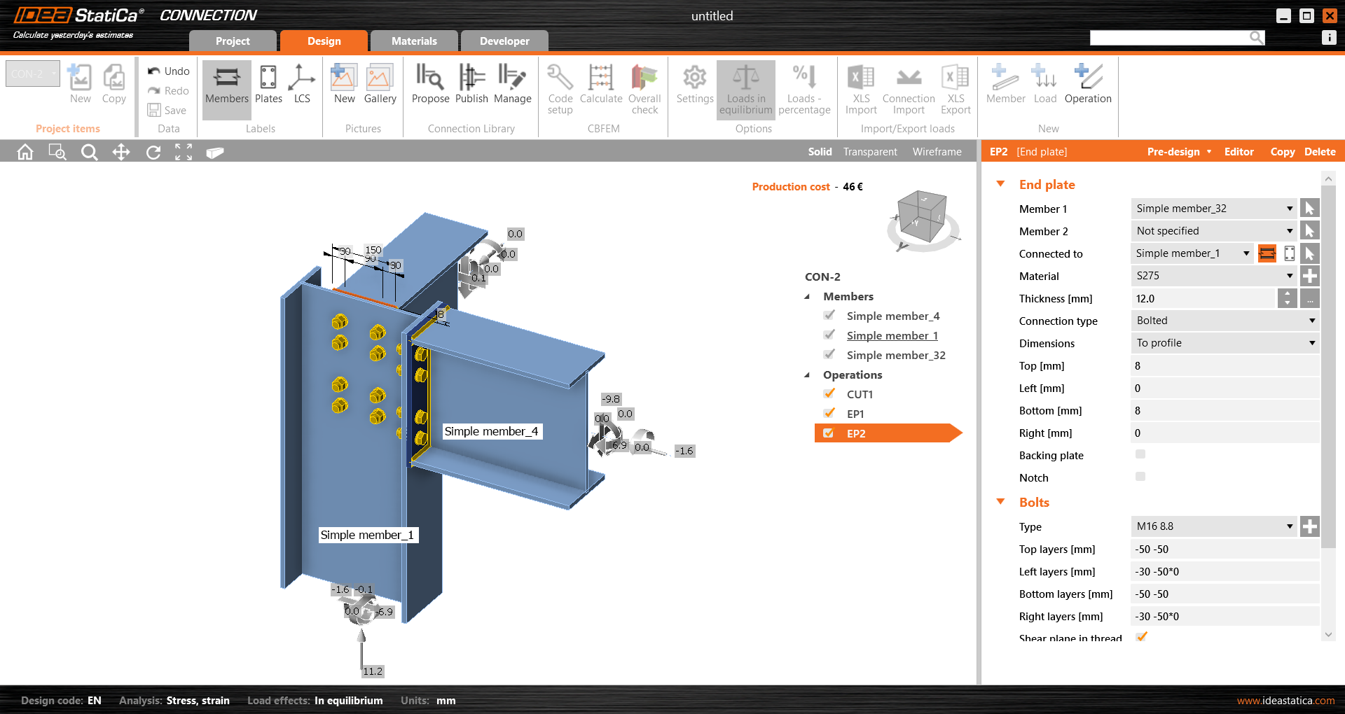
Speichern Sie diese Verbindung und kehren Sie zur Member-Anwendung zurück.
In diesem Beispiel haben alle Bauteile die gleiche Größe, sodass Sie dieselben Operationen sehr schnell auf Con-4 anwenden können.
Dies ist die endgültige Darstellung von Con-4.
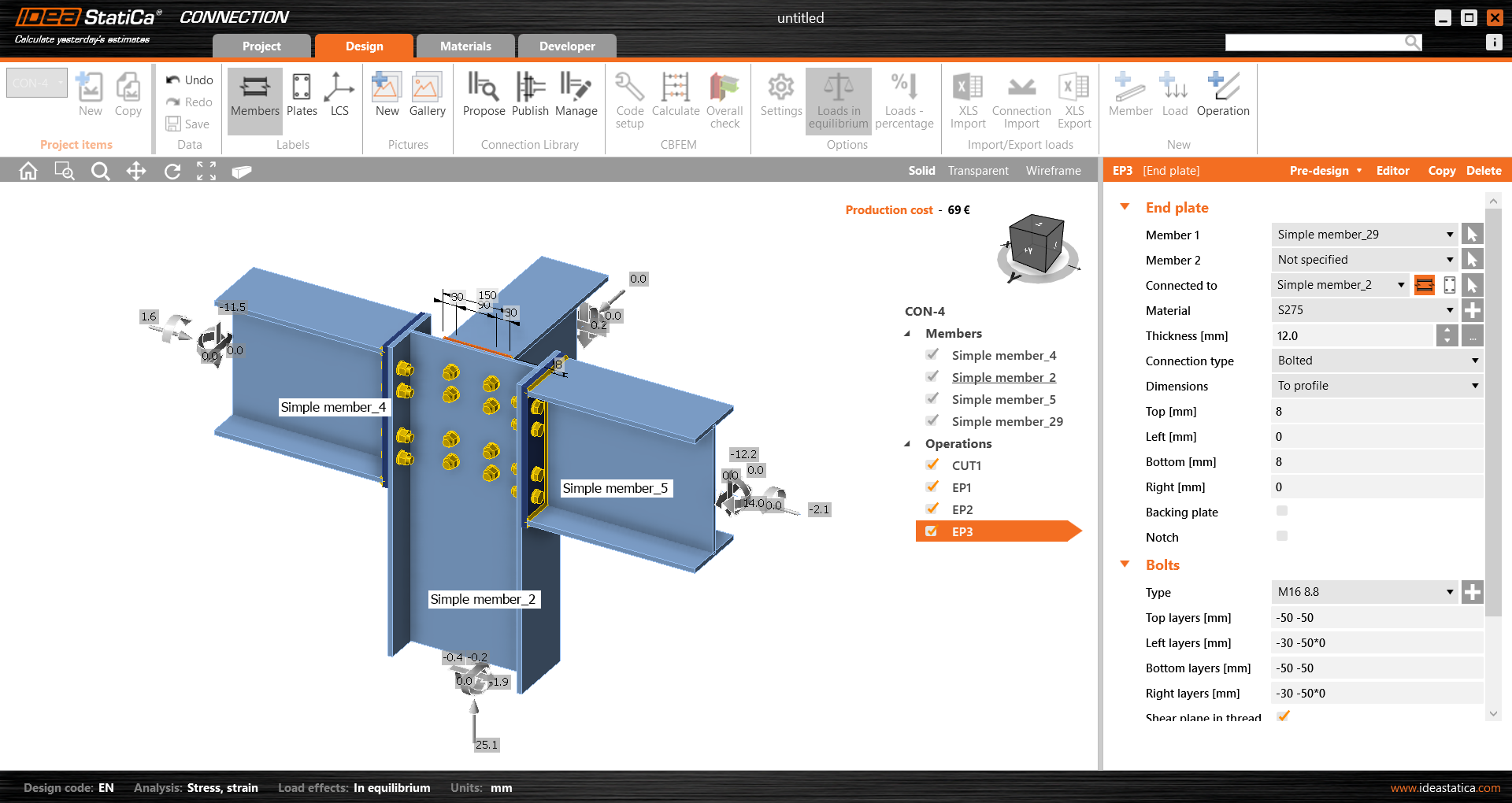
Speichern Sie auch dieses Verbindungsmodell und kehren Sie zur Member-Anwendung zurück. Die modellierten Verbindungen werden sichtbar sein.
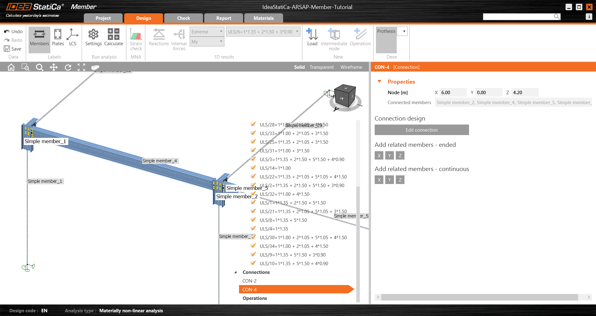
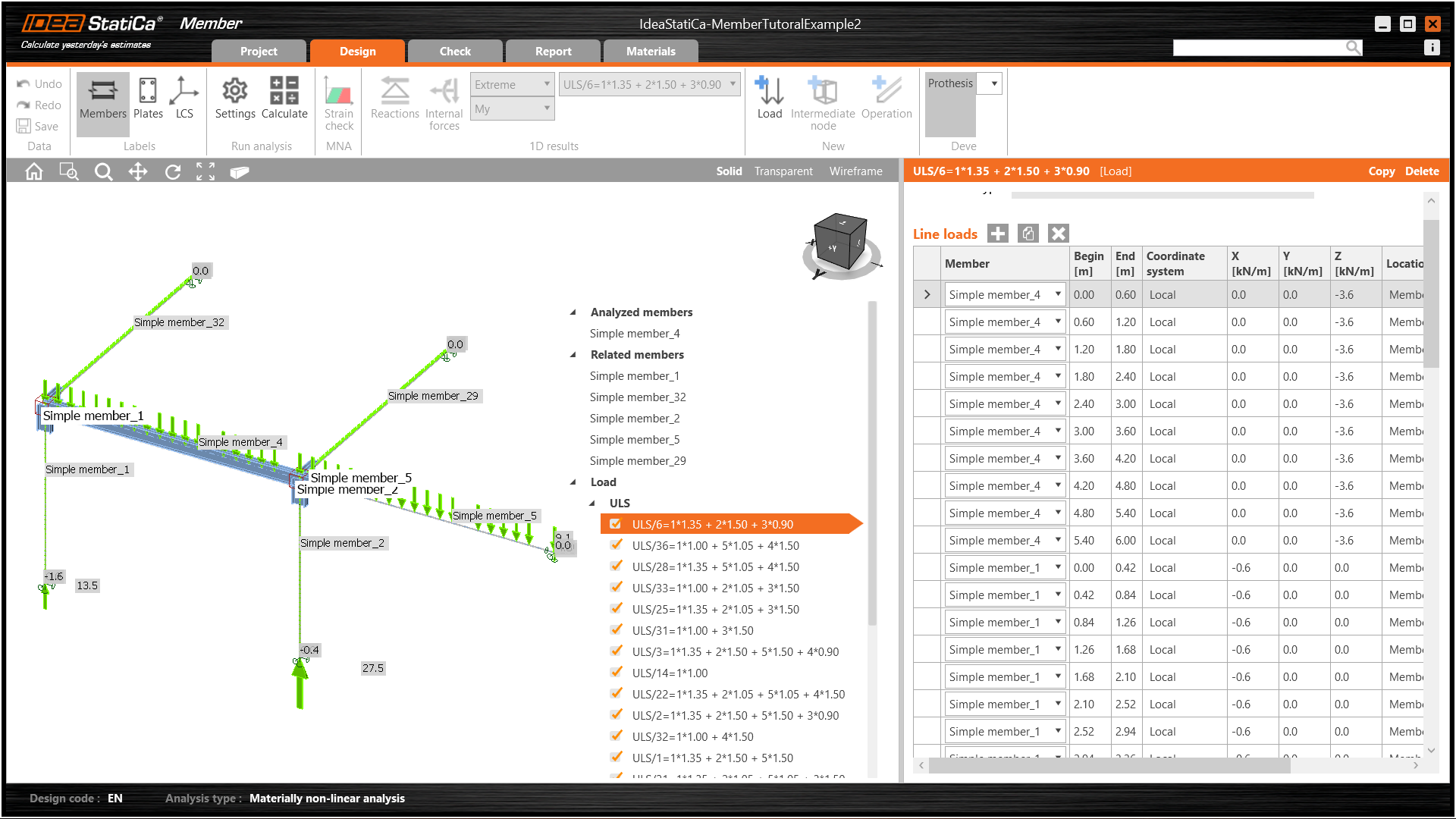
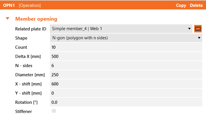
Alle Daten wie Geometrie und Lasten wurden importiert und alle Verbindungen wurden bemessen. Das Modell ist bereit für die Analyse, aber zunächst fügen wir dem Steg des Bauteils einige Öffnungen hinzu. Wählen Sie das Bauteil aus, klicken Sie dann im Strukturbaum auf Operationen und wählen Sie die Operation Öffnung.
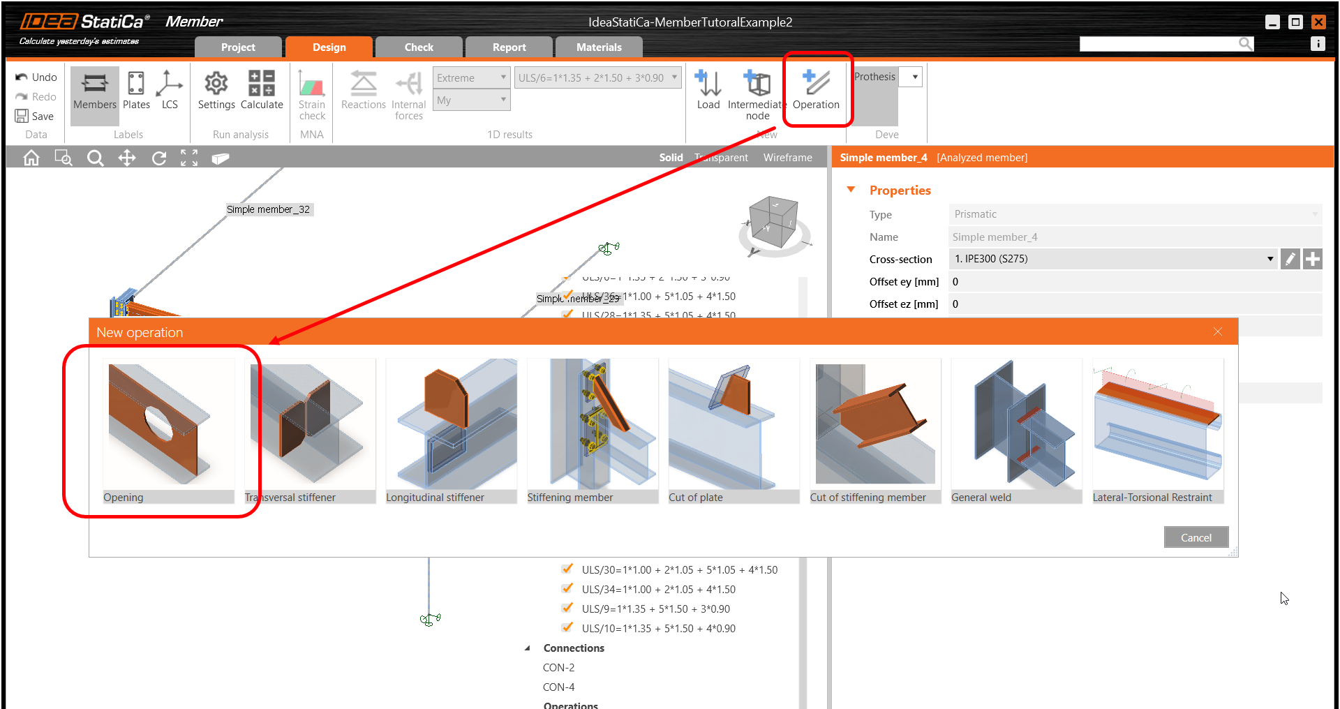
Bearbeiten Sie die Parameter der Operation, ändern Sie Größe und Form auf N-Eck (Polygon mit n Seiten) und erhöhen Sie die Anzahl der Öffnungen.
Normnachweis
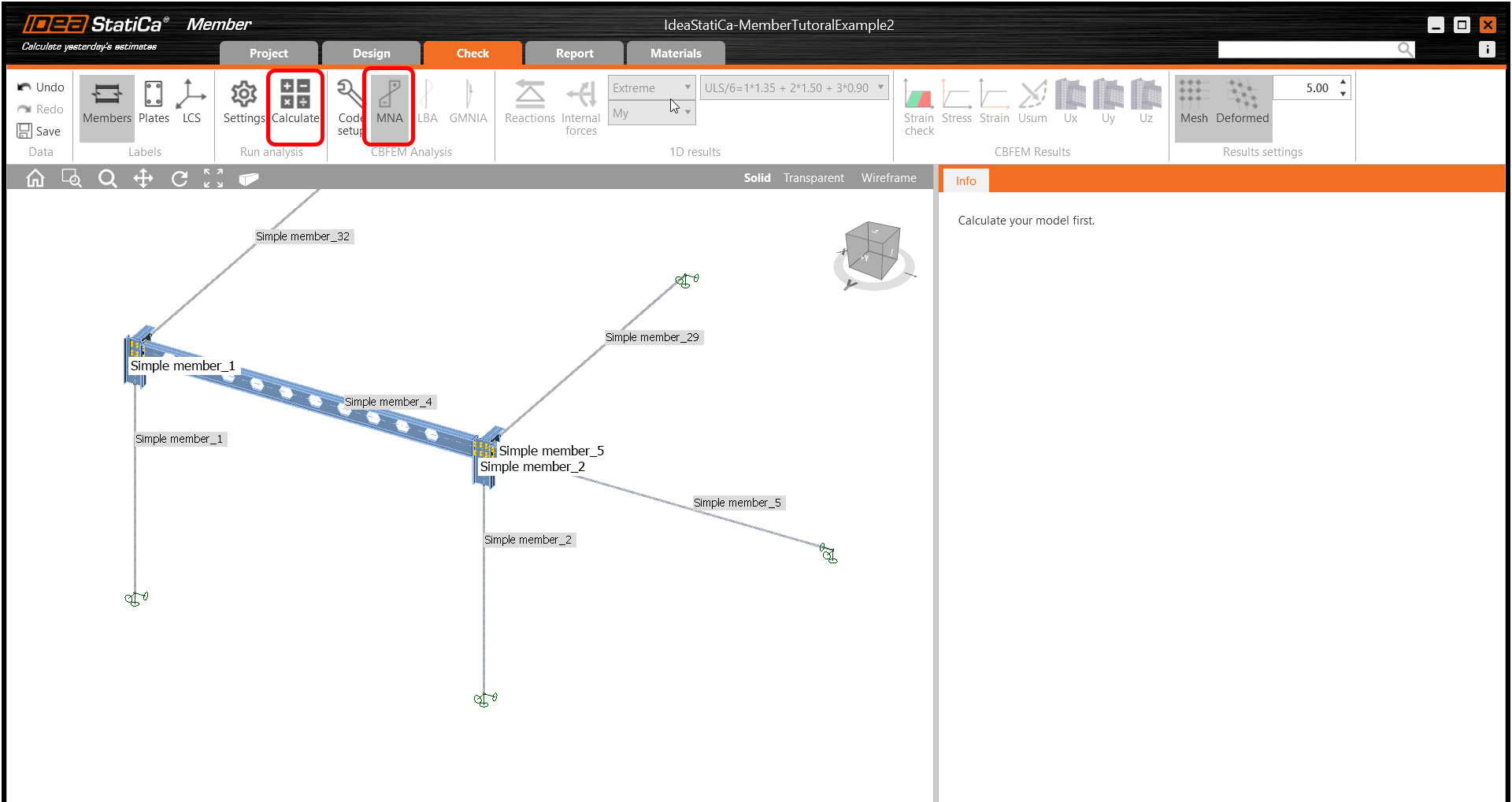
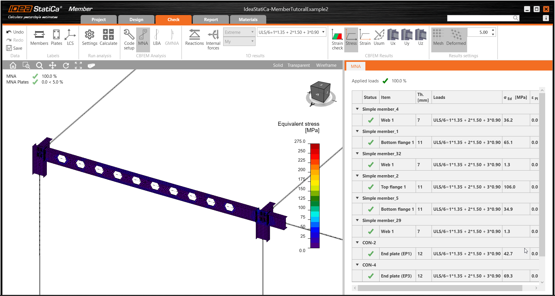
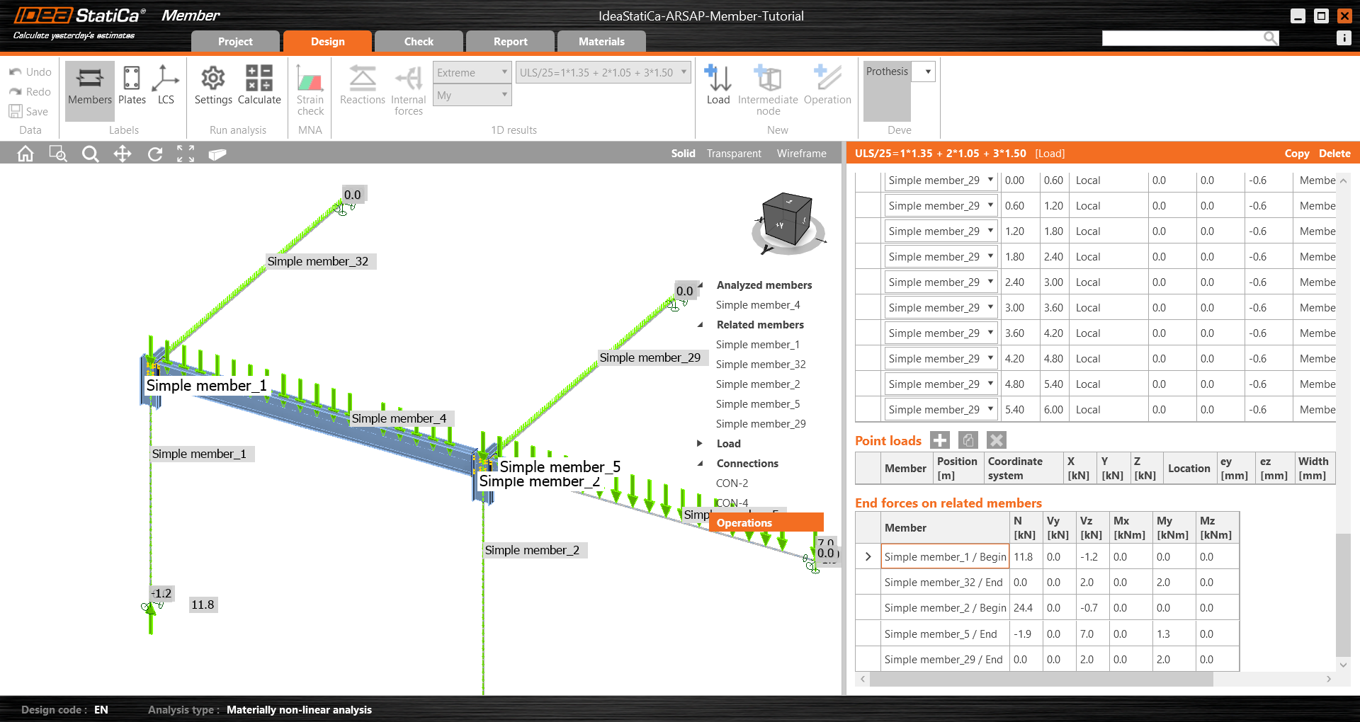
Wechseln Sie zur Registerkarte Normnachweis, wählen Sie die MNA (Materiell nichtlineare Analyse) und starten Sie die Analyse durch Klicken auf Berechnen im Menüband. Das Analysemodell wird automatisch generiert, die Berechnung wird durchgeführt und Sie können den Gesamtnachweis zusammen mit den grundlegenden Nachweisergebnissen anzeigen.
Wechseln Sie im nächsten Schritt den Analysetyp zu LBA (Lineare Beulanalyse) und führen Sie die Analyse erneut durch Klicken auf Berechnen aus.
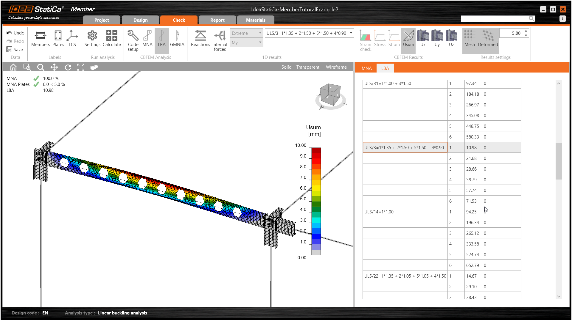
Nach Abschluss der Analyse können Sie die Beulformfaktoren in der Registerkarte durchsuchen, und durch Auswahl einer Form, z. B. Beulform 1, wird diese im 3D-Fenster visualisiert. Die Auswahl der Uy-Ergebnisanzeige hebt den Verformungstrend hervor.
Nun können Sie die GMNIA (Geometrisch und materiell nichtlineare Analyse mit Imperfektionen) berechnen. Wählen Sie gemäß EN 1993-1-1 die maßgebende Beulform oder eine Kombination von Beulformen und geben Sie die Anfangsimperfektionen des maßgebenden Trägers ein. In diesem Fall ist Beulform 1 die maßgebende. Wechseln Sie im rechten Bereich zur GMNIA-Registerkarte und bestimmen Sie die Imperfektion von 10 mm (0,5xL/300 = 0,5*6000/300 = 10 mm), die als Amplitude in Spalte 1 einzugeben ist. Klicken Sie auf die Schaltfläche Berechnen; diese Berechnung kann mehrere Minuten dauern.
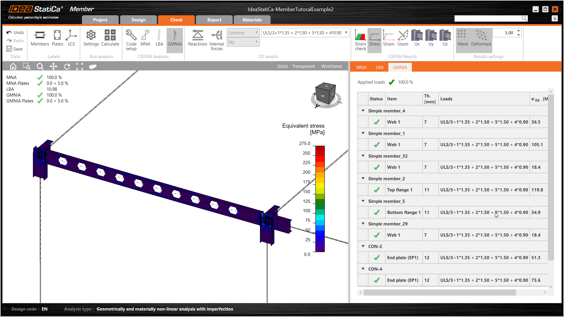
Das Bauteil hat die Normnachweise mit angewandten Anfangsimperfektionen bestanden und wir können die Ergebnisse wie Spannungsverteilung und Schnittgrößendiagramm durchsuchen.
Bericht
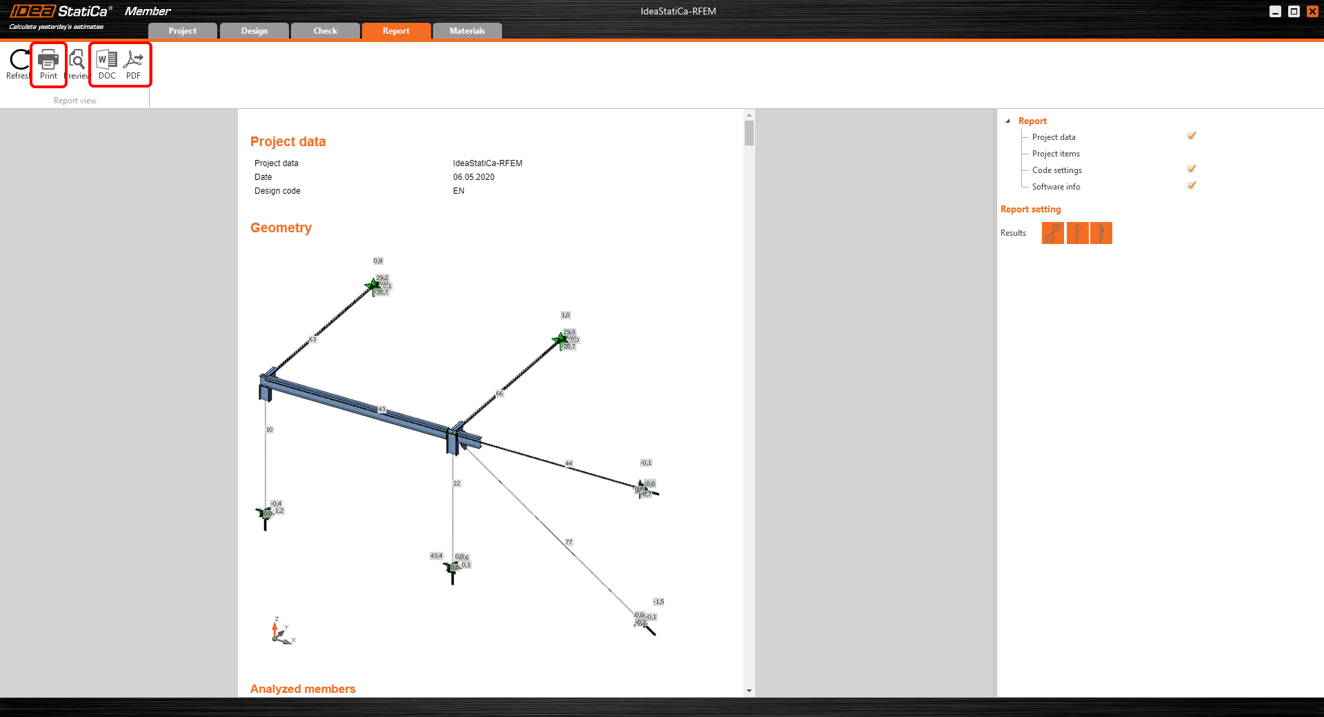
Wechseln Sie abschließend zur Registerkarte Bericht. IDEA StatiCa bietet einen vollständig anpassbaren Bericht, der ausgedruckt oder als .pdf oder .doc in einem bearbeitbaren Format gespeichert werden kann.
Sie haben ein Bauteil aus Autodesk Structural Analysis Professional importiert, es bemessen und den Normnachweis gemäß Eurocode (EN) geführt.
Speichern Sie das Projekt in IDEA StatiCa Member und schließen Sie es. Der nächste Prozess ist nur im Online-Betrieb verfügbar, d. h. bei aktiver Verbindung mit dem FEA-Modell und Checkbot, und bietet erhebliche Zeitersparnis bei Änderungen.
Modelle synchronisieren
Anstatt Modelle bei jeder FEA-Änderung neu zu erstellen, kann Checkbot seine Informationen mit denen der FEA-Anwendung synchronisieren.
Um die Synchronisierungsfunktion zu demonstrieren, ändern Sie den Querschnitt des analysierten Bauteils.
Berechnen Sie dann das Projekt in Autodesk Robot Structural Analysis Professional neu und öffnen Sie Checkbot erneut.
Wählen Sie das Bauteil aus der Liste aus und klicken Sie im Bereich „Aktuelles Element" auf Sync oder im Bereich „Strukturmodell" auf Sync, um das gesamte Modell zu aktualisieren.
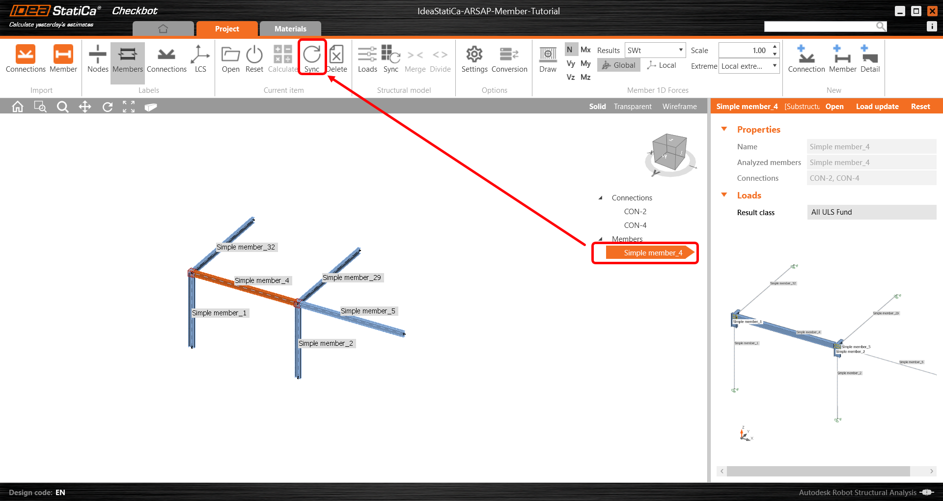
Die Geometrie und die Lasteffekte wurden aktualisiert und Sie können auf Öffnen klicken, um das Projektelement zu prüfen.
IDEA StatiCa öffnet sich und Sie können die aktualisierte Geometrie sehen, während die Bemessungsoperationen ihre Einstellungen beibehalten. Beachten Sie jedoch, dass einige Änderungen zu einer ungültigen Bemessung führen können und daher einem gründlichen Bemessungsprüfungsprozess unterzogen werden sollten.
Sie können die Bemessung prüfen und anpassen, neu berechnen und den Normnachweis des Bauteils führen, speichern und schließen. Anschließend können Sie weitere Verbindungen oder Bauteile importieren und den Normnachweis führen.
Möchten Sie Ihre Kenntnisse verbessern? Besuchen Sie unseren Campus
VERWANDTE INHALTE
Tragwerksplanung eines Stahlträgers
Automatische Bauteillänge
Anhänge zum Download
- Start - IdeaStatiCa-MemberTutorialExample.zip (ZIP, 306 kB)
- ARSAP-Member-Tutorial.rtd (RTD, 920 kB)