Beam-over-column Connections (AISC)
This verification example was prepared by Mark D. Denavit and Kayla Truman-Jarrell in a joint project of The University of Tennessee and IDEA StatiCa.
1 Description
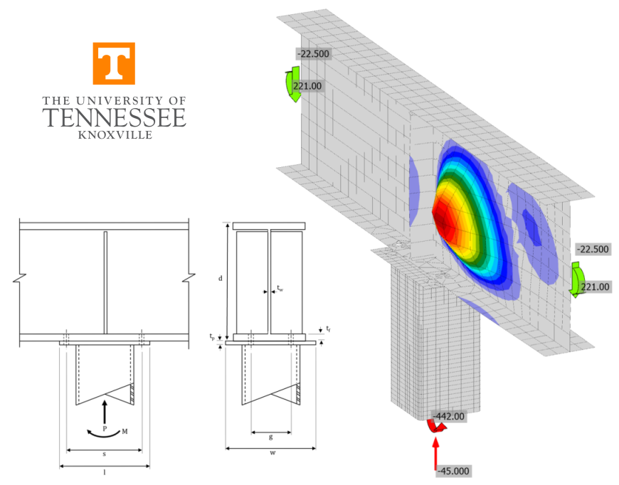
A comparison between results from the component-based finite element method (CBFEM) and traditional calculation methods used in US practice for beam-over-column connections is presented in this section. Connection limit states evaluated include beam web local yielding, beam web local crippling, HSS wall local yielding, HSS wall local crippling, cap plate bending, beam flange bending, and bolt tensile rupture. HSS member strength was also evaluated. A schematic of the beam-over-column connection investigated is presented in Fig. 1.

Fig. 1 Schematic of beam-over-column connection
The parameters of the connection change depending on the limit state being investigated. However, the typical connection has the following characteristics unless noted otherwise: (4) 3/4 in. diameter Group B (e.g., A490) bolts with spacing, s = 11 in. and gage, g = 3.5 in.; a W18 beam conforming to ASTM A992 (Fy = 50 ksi and Fu = 65 ksi); a 3/8 in. thick stiffener plate conforming to ASTM A36 (Fy = 36 ksi and Fu = 58 ksi); a 9 in. by 14 in. by 3/4 in. thick cap plate; and a HSS8x8 column conforming to ASTM A500 Gr. B (Fy = 46 ksi and Fu = 58 ksi).
The traditional calculations were performed in accordance with the provisions for load and resistance factor design (LRFD) in the AISC Specification (2016) with prying action considered as described in Part 9 of the AISC Manual (2017). The connections and method of evaluation were modeled after Example 4.1 of AISC Design Guide 24 (Packer et al. 2010). The axial load and moment are resolved to a force couple, the compression force is assumed to be centered at the face of the HSS and the tensile force is assumed to be centered at the centerline of the bolts.
The CBFEM results were obtained from IDEA StatiCa Version 21.0. Loads were applied using the “Loads in Equilibrium” function to minimize the bending moment in the beam at the connection. For all analyses, the axial load was taken as constant, and the maximum permitted bending moment was determined iteratively by adjusting the applied load input to a value that met all limits; but if increased by a small amount (1 kip-in) would exceed the limits. Buckling analyses were performed and a limit of 3.00 on the buckling factor was enforced.
2 HSS Column Local Yielding and Crippling
First, the limit states of local yielding and local crippling of the wall of the HSS column are investigated. Connections with five different beam sections (W18x35, W18x40, W18x46, W18x76, and W18x86) were analyzed. The beams have different flange thicknesses and thus distribute the load to the column differently. The cap plate conformed to ASTM A572 Gr. 50 (Fy = 50 ksi and Fu = 65 ksi). The column was a HSS8x8x3/16 which has a nominal moment strength of Mn = 580.5 kip-in and cross-sectional axial strength of Pn = 216.7 kips. The applied axial load was Pu = 45 kips for all analyses.
The maximum factored moment is presented in Fig. 2. The limiting buckling factor of 3.00 controlled the strength of all connections in IDEA StatiCa. The strength increases slightly from 314 kip-in to 328 kip-in as the beam size increased and more evenly distributed the load to the wall of the HSS. An example of the buckling mode computed by IDEA StatiCa is presented in Fig. 3.
The strength according to the traditional calculations exhibited greater variation as the beam size increased, from 357 kip-in to 452 kip-in. HSS wall local yielding controlled for the connection with the W18x35 beam. HSS wall local crippling controlled for the connections with the W18x40 and W18x46 beams. HSS member strength controlled for the connections with the W18x76 and W18x86 beams.
These results indicate that limiting the buckling factor to 3.00 can be conservative. However, there was some indication that there was no significant reserve capacity beyond the buckling factor limit. Analyses in IDEA StatiCa were performed both with geometric nonlinearity on and with geometric nonlinearity off. Given that the boundary conditions were applied to the HSS member for this connection, geometric nonlinearity was on by default. Since the buckling factor limit was controlled in all cases, there was no difference between the strength results between geometric nonlinearity on or off. However, for some cases and with geometric nonlinearity on, the strain increased rapidly with small increases in applied load shortly after the buckling limit was reached.
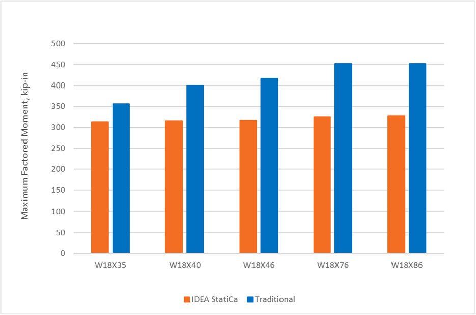
Fig. 2 Comparison of results investigating HSS column local yielding and crippling
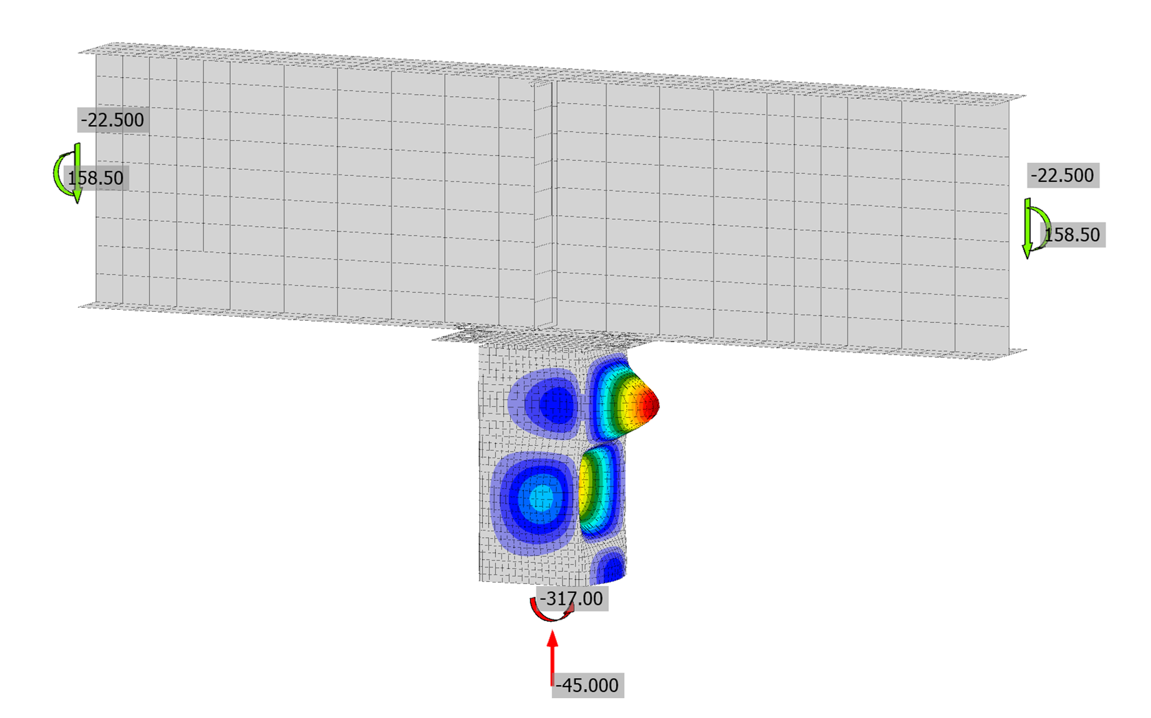
Fig. 3 Buckled shape for beam-over-column connection with a W18X40 beam
3 Beam Web Local Yielding and Crippling
Next, the limit states of local yielding and local crippling of the web of the wide flange beam are investigated. The beam for these analyses was a W18x40, but with the thickness of the web overridden to values of 0.30 in. 0.25 in. and 0.20 in. The connection was also analyzed with the beam’s standard thickness of 0.315 in. Overriding the thickness allowed precise control of the thickness of the web in relation to other beam parameters. The cap plate conformed to ASTM A36 (Fy = 36 ksi and Fu = 58 ksi). The column was a HSS8x8x1/2 which has a nominal moment strength of Mn = 1725 kip-in and cross-sectional axial strength of Pn = 621 kips. The applied axial load was Pu = 45 kip for all analyses.
The maximum factored moment is presented in Fig. 4. The controlling limit state for each analysis is presented in Table 1. The beam web local limit states controlled when the thickness was reduced significantly. The buckling mode computed by IDEA StatiCa for the analysis with beam web thickness of 0.20 in. is presented in Fig. 5. For larger thicknesses, the tension side of the connection controlled with bending of the cap plate, bending of the beam flange, bolt tension, or a combination of these limit states controlling. Analyses were performed in IDEA StatiCa with geometric nonlinearity on and geometric nonlinearity off. Both sets of results are presented in Fig. 4. There is only a small difference between the two.
When the beam web thickness is overridden to 0.20 in. or 0.25 in., local crippling of the beam web controls the strength per the traditional calculations. Buckling of the beam web controls the strength per IDEA StatiCa for the connection with beam web thickness of 0.20 in., but not for the connection with beam web thickness of 0.25 in. For both connections, IDEA StatiCa produces strengths greater than that from the traditional calculations. The discrepancy could be due to several factors. The traditional calculations do not account for the stiffener, which appears to influence the buckling mode (Fig. 5). The finite element mesh in IDEA StatiCa may also be too coarse.
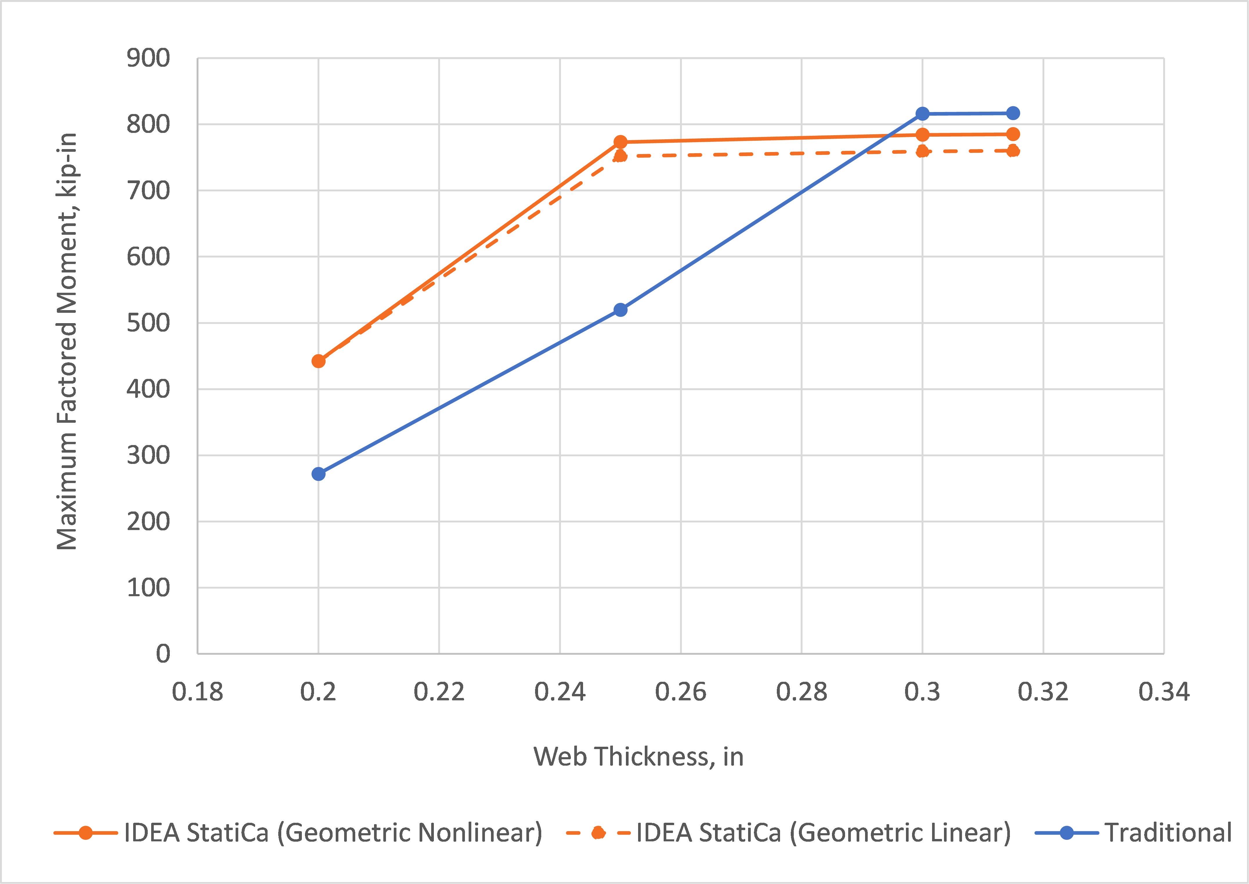
Fig. 4 Comparison of results investigating beam web local yielding and crippling
Table 1. Controlling limit state for results presented in Fig. 4
| Web Thickness (in.) | IDEA StatiCa | Traditional |
| 0.200 | Buckling (beam web) | Local crippling of the beam web |
| 0.250 | Plastic strain (cap plate) | Local crippling of the beam web |
| 0.300 | Plastic strain (cap plate) | Beam flange bending and bolt tension |
| 0.315 | Plastic strain (cap plate) | Beam flange bending and bolt tension |
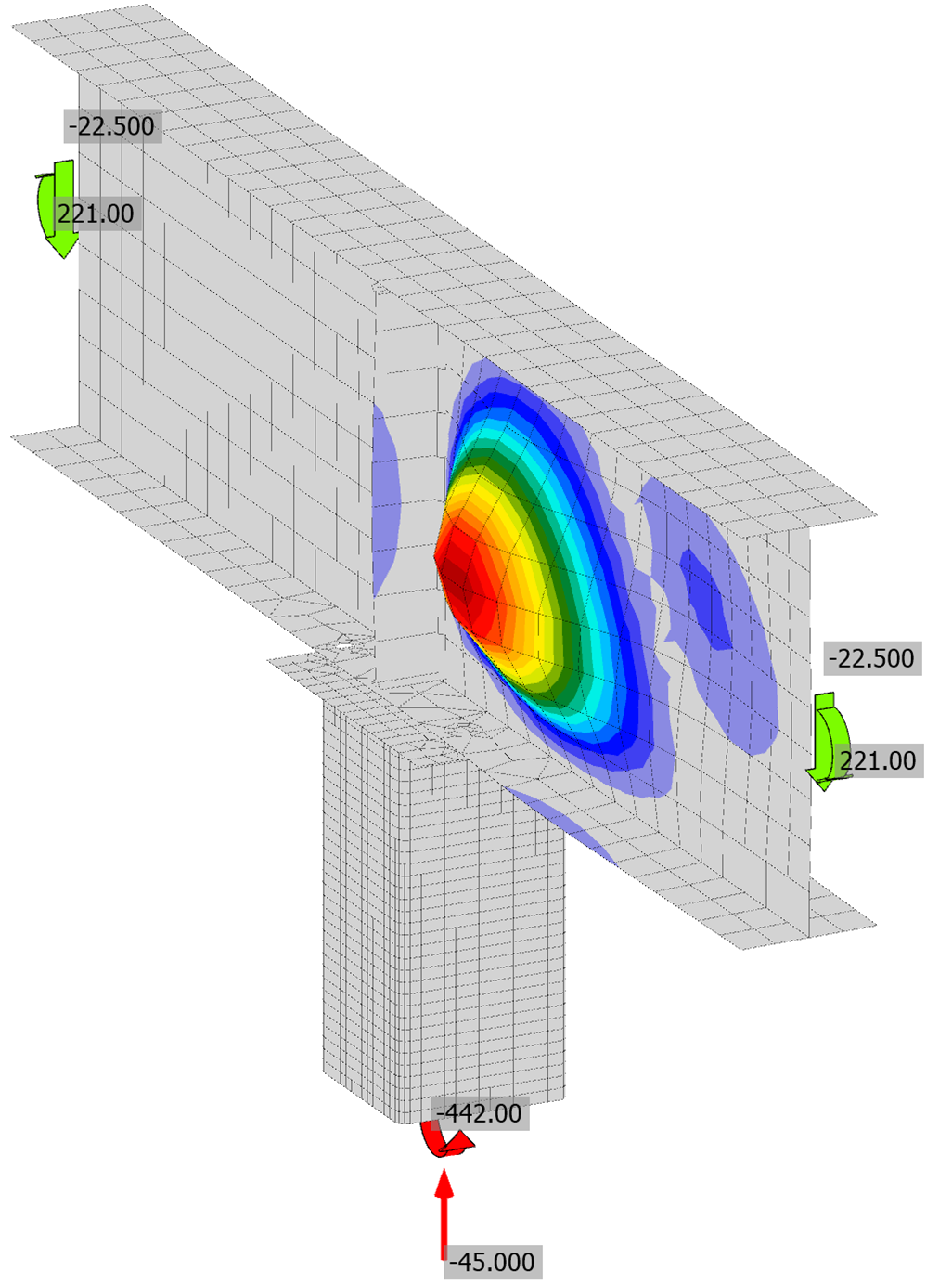
Fig. 5 Buckled shape for beam-over-column connection with a W18X40 beam with web thickness overridden to 0.2 in.
A mesh sensitivity study was performed to bring greater insight to the results. IDEA StatiCa analyses were repeated for each of the four connections presented in Fig. 4 using different maximum element sizes. The analyses of this mesh refinement study were performed with geometric nonlinearity turned on. The results of the mesh refinement study are presented in Fig. 6.
Overall, the results show a significant mesh dependence for this connection. The maximum factored moment capacity decreases as the size of the mesh decreases. Additionally, in some instances, the failure mode changes with the refinement of the mesh. For the connections with web thicknesses of 0.25 in. and 0.30 in., the controlling limit state transitions from exceeding the strain limit in the cap plate at the default mesh size (1.969 in.) to exceeding the strain limit in the beam web for the decreased maximal element sizes. Note that cap plate bending was not expected to occur per the traditional calculations. The maximal element size also impacts the buckling results. For the connection with a beam web thickness of 0.20 in., the buckling factor limit controls. The applied load at which the limit is reached decreases with mesh size and appears to converge at a maximal element size of 0.50 in.

Fig. 6 Comparison of results investigating beam web local yielding and crippling – showing mesh sensitivity study
Another potential reason for the discrepancy in results between the traditional calculations and IDEA StatiCa is the stiffener in the beam centered above the column. Since the stiffener is not located in line with the concentrated force (i.e., the wall of the column) it is not considered in the traditional calculations. The stiffener is included in the model and thus is considered by IDEA StatiCa.
Analysis of a simpler connection (Fig. 7) was performed to evaluate the magnitude of the effect of a nearby stiffener. For this analysis, the beam was a W18x40 (A992) with web thickness overridden to tw = 0.25 in. The beam was loaded by a 1 in. thick plate and 3/8 in. thick plate stiffeners were located 0.25 times the beam depth to 2 times the beam depth away from the centerline of the loading plate.
Analyses were performed to determine the maximum permitted applied load from IDEA StatiCa and Section J10 of the AISC Specification (2016) for the limit states of web local yielding and web local crippling (Fig. 8). The results of the traditional calculations do not consider the stiffener and do not vary with the position of the stiffener. Two results are shown for the traditional calculations. One where the k dimension (i.e., the distance from outer face of flange to the web toe of fillet) was taken as the value of k listed in the Part 1 of the AISC Manual (2017) for the beam and one where the k dimension was taken as tf, the thickness of the flange. IDEA StatiCa does not explicitly model the fillet of the wide flange shapes. Two results are also shown for IDEA StatiCa, one with the default mesh size and one with a mesh size of 0.3 in.
Local web yielding controls for the traditional calculations for all cases. The plastic strain limit controls for IDEA StatiCa for the stiffener located one-quarter the beam depth from the applied load and the buckling limit controls otherwise. For the nearby stiffeners, IDEA StatiCa exhibits a greater strength than the traditional calculations. However, as the distance to the stiffener increases, the strength from IDEA StatiCa reduces, eventually settling below the strength from the traditional calculations. The strength from traditional calculations for k = tf is still lower, but this case is shown for informational purposes and not for direct comparison. Regardless, these results demonstrate that IDEA StatiCa captures the stiffening effect of nearby stiffeners which contributed to the discrepancy in results shown in Fig. 4.

Fig. 7 Connection to evaluate the effect of nearby stiffener

Fig. 8 Maximum applied load vs ratio of stiffener location to beam depth
4 Axial Compression / Bending Moment Interaction
Lastly, the variation of moment strength with the level of axial load is investigated. The traditional calculations utilize simple assumptions to convert the applied axial load and bending moment to a force couple. IDEA StatiCa computes the distribution of stresses explicitly. The beam for these analyses was a W18x35. The cap plate conformed to ASTM A572 Gr. 50 (Fy = 50 ksi and Fu = 65 ksi). The column was a HSS8x8x3/16 which has a nominal moment strength of Mn = 580.5 kip-in and cross-sectional axial strength of Pn = 216.7 kips.
An interaction diagram showing the maximum factored moment for each selected axial load is presented in Fig. 9. The controlling limit state for each analysis is presented in Table 2. Analyses were performed in IDEA StatiCa with geometric nonlinearity on and geometric nonlinearity off. Both sets of results are presented in Fig. 9. For most cases, where the buckling factor limit controlled, there is no difference between the two. Differences were noted for applied axial loads of 75 kips and 100 kips.
For the connection with 75 kips applied axial load, when geometric nonlinearity was off, the buckling limit was reached at an applied moment of 225 kip-in. When geometric nonlinearity was on, the strain limit was reached at an applied moment of 222 kip-in. Important to note is that the strain limit was not reached gradually, rather, a large increase in strain (~3%) was noted for a small increase applied moment (1 kip-in) immediately prior to reaching the limit.
For the connection with 100 kips applied axial load, when geometric nonlinearity was off, the buckling limit was reached at an applied moment of 146 kip-in. When geometric nonlinearity was on, an applied load of 131 kip-in resulted in a buckling factor of 3.10 and maximum strain of 2.2%. For greater applied loads, the analysis was unable to complete, indicating that a limit point had been reached. The maximum factored moment was taken as the greatest applied moment for which the analysis completed 100%.
For both of these analyses, IDEA StatiCa provided greater strength than the traditional calculations. Further investigation is warranted to determine if an inelastic buckling analysis would be more appropriate or if other changes to the manner in which this connection is evaluated are necessary.

Fig. 9 Comparison of results investigating axial compression/bending moment interaction
Table 2. Controlling limit state for results presented in Fig. 9
| Axial Load, (kips) | IDEA StatiCa (GMNA ON) | IDEA StatiCa (GMNA OFF) | Traditional |
| 0 | Buckling (HSS wall) | Buckling (HSS wall) | HSS member strength |
| 25 | Buckling (HSS wall) | Buckling (HSS wall) | Local yielding of HSS wall |
| 50 | Buckling (HSS wall) | Buckling (HSS wall) | Local yielding of HSS wall |
| 75 | Strain limit (HSS wall) | Buckling (HSS wall) | Local yielding of HSS wall |
| 100 | Limit point reached in analysis | Buckling (HSS wall) | Local yielding of HSS wall |
| 125 | Buckling (HSS wall) | Buckling (HSS wall) | Local yielding of HSS wall |
| 134 | Buckling (HSS wall) | Buckling (HSS wall) | n/a |
5 Summary
This study compared the design of beam-over-column connections by traditional calculation methods used in US practice and IDEA StatiCa. Key observations from the study include:
- The available strength obtained from IDEA StatiCa agrees well with the traditional calculations with differences primarily on the conservative side.
- For the cases examined, limiting the buckling factor to 3.00 was found to be an effective and conservative means of limiting the effects of geometric nonlinearity and considering elastic stability limit states.
- IDEA StatiCa considers the effect of nearby stiffeners which impacts the strength web local limit states.
- Some mesh dependence was observed. IDEA StatiCa exhibited reduced strengths when the mesh size was set smaller than the default.
6 References
AISC. (2016). Specification for Structural Steel Buildings. American Institute of Steel Construction, Chicago, Illinois.
AISC. (2017). Steel Construction Manual, 15th Edition. American Institute of Steel Construction, Chicago, Illinois.
Packer, J., Sherman, D., and Lecce, M. (2010). Hollow Structural Section Connections. Design Guide 24, American Institute of Steel Construction, Chicago, Illinois.