Prestressing in Detail - Pre-tensioned strands
Introduction and assumptions
First, let's start with a brief description of our concrete design software. This article is mainly about prestressed concrete design in the Detail application which is generally developed for discontinuity regions design or for the design of members containing discontinuity regions such as openings, dapped ends etc.
For comparison of results, we will use the Beam application whose purpose, as you can guess from the name, is concrete beam design.
Secondly, we need to define a few assumptions and restrictions to understand the design of prestressed concrete beams in Detail better.
- The Time Depended Analysis (TDA) is not implemented in the Detail application. On the other hand, TDA is implemented in the Beam app. for the design of prestressed concrete beams.
- TDA can be simulated in Detail using the creep coefficient and the increments.
- Shrinkage and temperature loads are not implemented in the Detail
- The concrete in tension in the Detail is excluded. So for our comparison, we need to have the beam without cracks. Of course, the same approach can be used generally for beams affected by cracks, but the results will not be then the same in the Beam because only linear calculation is provided in the Beam.
Increments
Before we go through the example, we need to understand how the increments work for prestressed concrete design in the Detail.
There are 3 load types that are applied to the model in three increments in the Detail app.
- Prestressing - for increment P
- Permanent - for increment G
- Variable - for increment V
If you create a combination containing load cases of all load types, the whole portion of Prestressing load type will be applied in the first increment P, the whole portion of Permanent load type will be applied in the second increment G, and the whole portion of Variable load type will be applied in the third increment V.
The reason why there are increments is that the different material models (different modules of elasticity) are used for SLS calculations (for ULS there is only one material model defined in Material model (EN)).

As you can see there are three modules of elasticity:
- Ec,eff,press = Ecm / (1+φpress) - Effective modulus of elasticity of concrete for P increment
- Ec,eff,perm = Ecm / (1+φperm) - Effective modulus of elasticity of concrete for G increment
- Ecm - Secant modulus of elasticity of concrete
Where the φpress and φperm are the creep coefficients for the P and G increments. The coefficients can be set in Materials & models.
Please note that for short-term effects only Ecm is used. It is valid for all three increments. And the long-term loss is taken into account only for long-term effects.
The beam parameters
Two identical models are created in the Beam and Detail applications. They are attached at the end of this article. Download them and go through them while reading the article.
The example of a concrete beam will be introduced in the Beam application and then the comparison with Detail will be done for three construction stages.
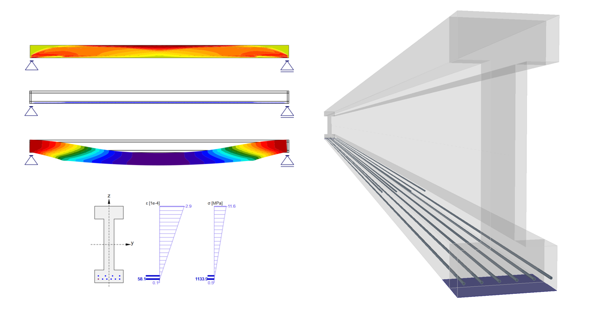
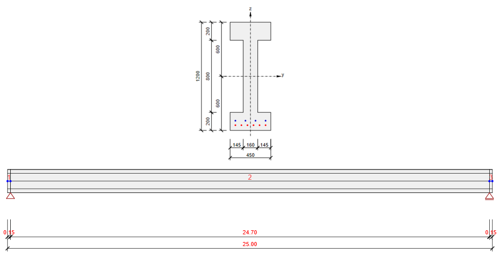
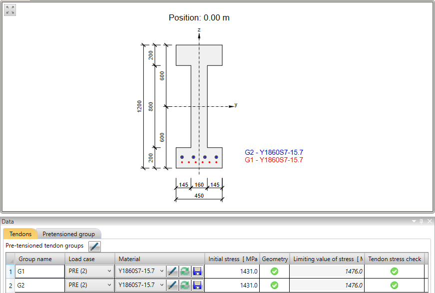
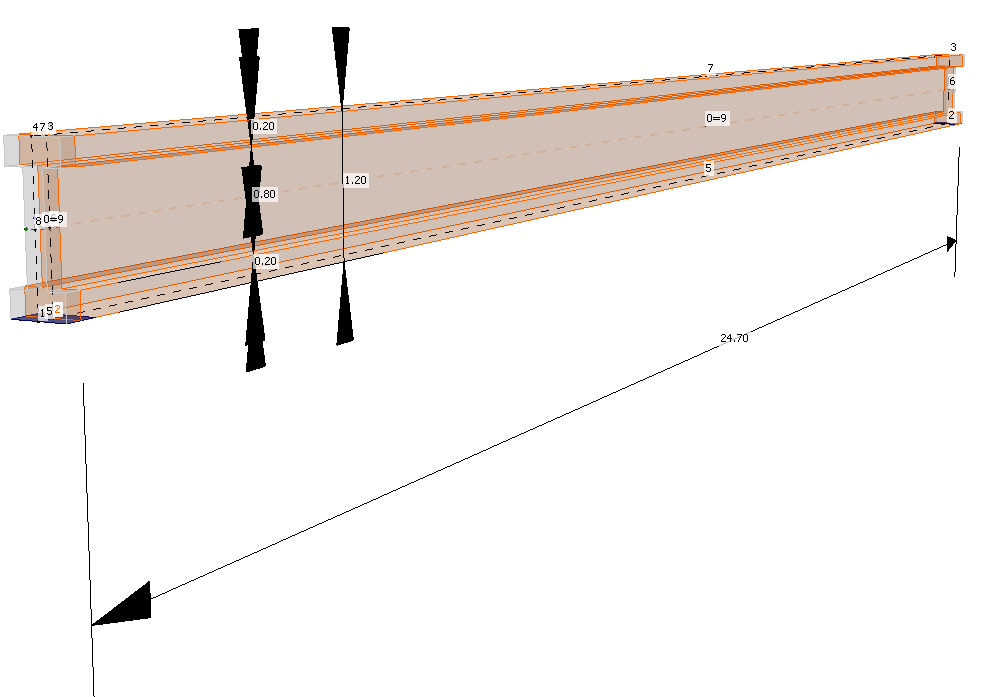
The example is a single span simple beam of I cross-section made of C45/50 concrete prestressed by pre-tensioned strands.
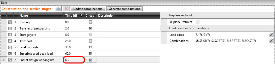
We will check the beam in three construction stages:
- Transfer of prestressing - 2 d (just after release)
- Superimposed dead load - 60 d (start of design working life)
- End of design working life - 18250 d (50 years)
The other stages can be carried out similarly.
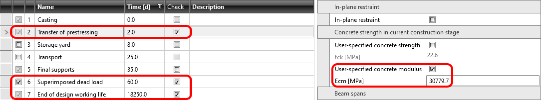
You will notice, that we used the user-specified concrete modulus. Read more in: How to input compressive strength value of concrete in construction stage?. That is because we want to show, how to model the beam which is prestressed before the concrete reaches the 28-day modulus of elasticity.
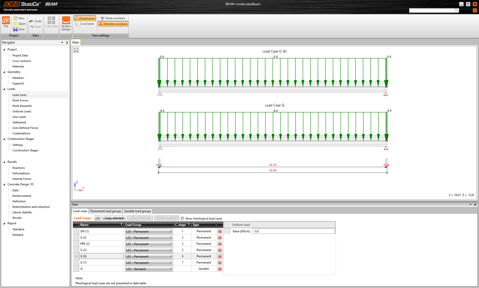
There are only four load cases input. The numbers in the brackets are the numbers of the construction stages where the individual loads are applied.
- Self-weight - SW (1)
- Prestressing - PRE (2)
- Permanent load - G (6)
- Variable load - Q
Other load cases are empty.
Now let's take a look at the prestressing. There are two rows of strands. It is worth mentioning, that the upper row has a blanketed length 3.0 m.
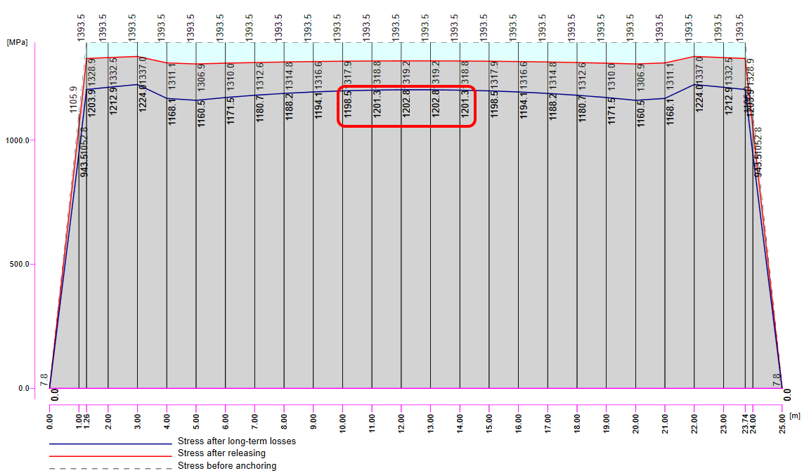
In the next figure, you can see the Tendon Stress/Losses chart.
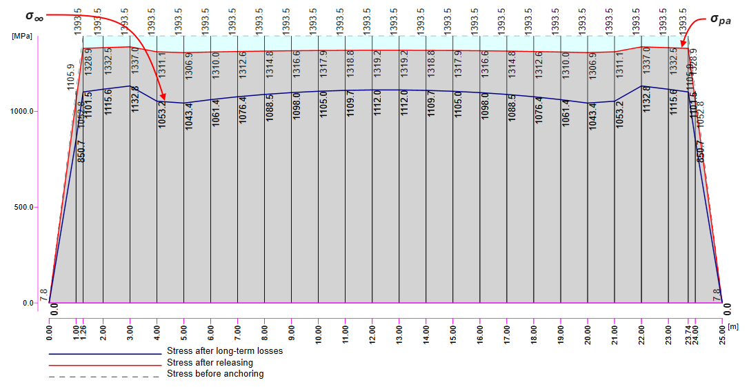
There are several values of stress in the tendon that should be controlled during the prestressing application. At this point, we will stop and briefly explain the prestressing process and individual stresses and losses.
Prestressing process for pre-tensioned beam
Stage 0 - stressing of strands -> The strands are prepared to their position, anchored on one side and prestressed by stressing jack on the other site.
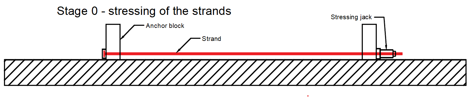
- σp,ini - Initial stress - maximum stress during tensioning. It has to be lesser than σp,max according to EN 1992-1-1 5.10.2.1. It is stress on the stressing jack. In our example σp,ini = 1431 MPa.
Stage 1 - casting -> The concrete member is being cast around the prestressed tendons in this stage.
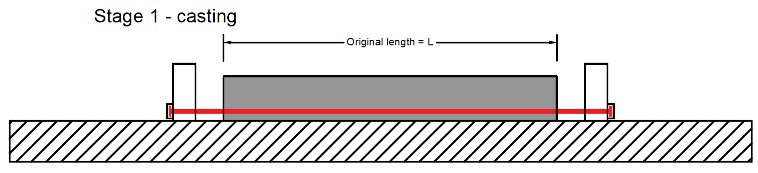
- σpr,cor - Stress after short-term relaxation that also includes anchorage set loss and loss due to the deformation of abutments. In our example σpr,cor = 1415 MPa
Stage 2 - releasing of strands -> The strands are released and the immediate elastic concrete strain is realized.
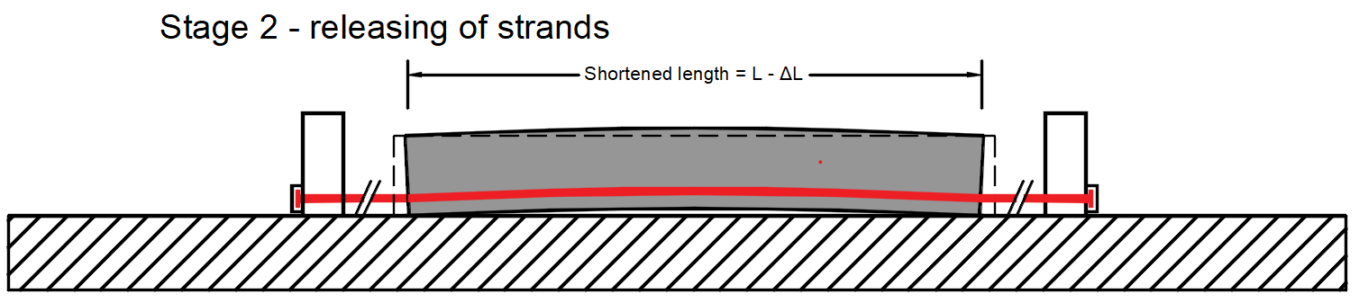
- ΔσpT - Loss due to difference of temperature of prestressing steel and stressing bed.
- σpm0 - Stress just before release - This value is the input to the Detail. It is also the stress before the loss due to immediate elastic concrete strain - Δσpe. It is calculated as σpm0 = σpr,cor - ΔσpT. In our example σpm0 = 1386 MPa
- Δσpe - Loss due to immediate elastic concrete strain.
- σpa - Stress after short-term losses. In other words, it is a stress after the transfer of prestressing to the member. It is calculated as σpa = σpr,cor - ΔσpT - Δσpe = σpm0 - Δσpe. In our example σpa = 1319.2 MPa
Stage 3 - end of working life
- σ∞ - Stress after long-term losses
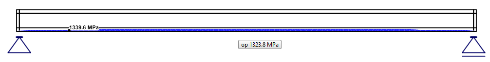
Now recall the figure above (with the Tendon Stress/Losses chart) where the values of σpa (red line) and σ∞ (blue line) are displayed.
- Read more: Prestressing in Detail - Model description
Transfer of prestressing stage
The model is defined, so let's switch to the Detail application and have a look at how to set the first stage. The model is the same, we only added stirrups for shear transfer, but it will not influence the results.
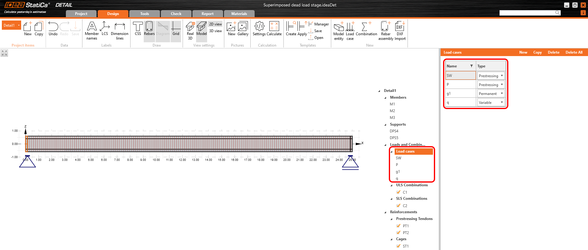
For this stage, there are only two load cases:
- SW - Prestressing type (Self-weight)
- P - Prestressing type (Prestressing)
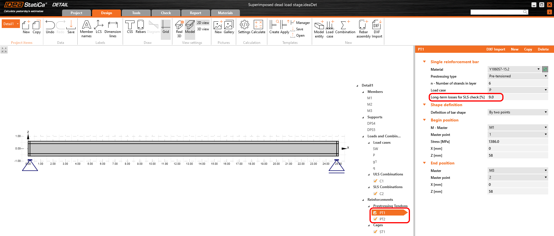
Both of them will be applied in the first load increment. Long-term losses for SLS checks are set to 0% as you can see.

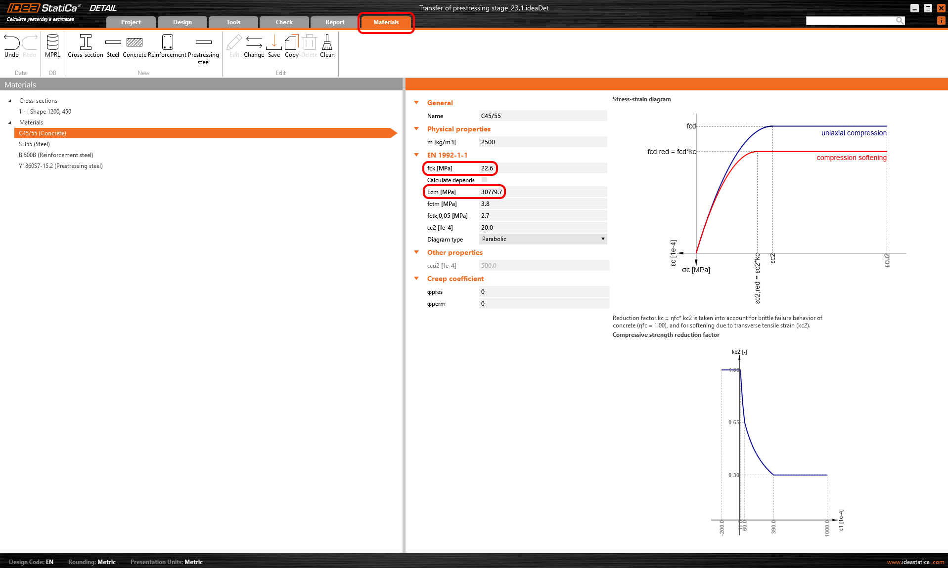
Creep coefficients are also set to zero value because we want to assess the stage just after the transfer of prestressing. And, you can see that the value of Ecm was rewritten to the same value we input into the Beam application.
So let's compare the results. Because we didn't input any creep factor or long-term loss, the long-term and short-term effects are the same.
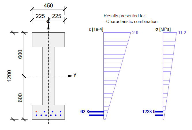
Stress in tendons in SLS:
Stress in concrete in SLS:
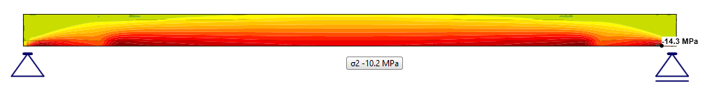
The SLS section check from Beam:
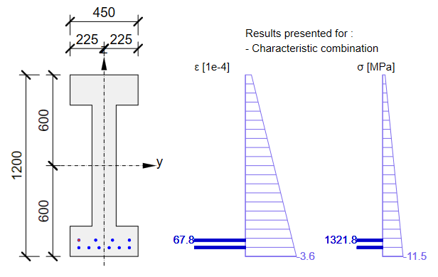
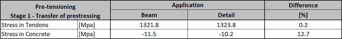
As you can see there is a good match. So it seems we have done the input for this stage correctly. Note that the coefficients rinf and rsup defined in EN 1992-1-1; 5.10.9 (1) was set as 1.0 in the Beam application.
On the other hand, for the ULS check, we can expect a significant difference between the Beam and Detail applications results. It will be caused by the loss due to immediate elastic concrete strain - Δσpe, which is calculated differently in Beam (linear approach) and in Detail (CSFM).
- In the linear approach (Beam application), loss due to immediate elastic concrete strain Δσpe is the same for ULS and SLS. The reason is that in the case of the linear approach, we use the linear material model with the modulus of elasticity Ecm, calculated from fck, for the whole analysis (also for the analytical calculation of losses) and only for ULS cross-sectional checks, we use the material model where the modulus of elasticity is calculated from fcd.
- In the Detail application approach, the whole ULS is calculated with the material model where the modulus of elasticity is calculated from fcd (also influenced by ηfc factor, see Material models (EN)). It causes greater elastic strain and consequently greater loss Δσpe. Please recall that we input the stress before loss due to immediate elastic concrete strain. This loss is calculated based on the strain of the model affected by prestressing forces (in the case of ULS with the lower modulus of elasticity).
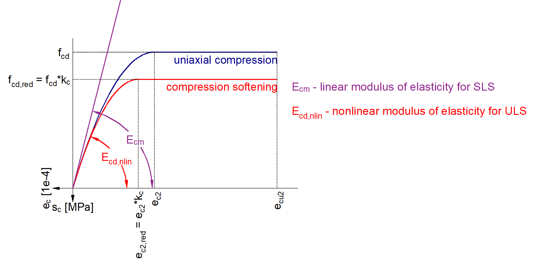
Note that SLS is calculated in the Detail application based on Ecm (not based on fck). On the other hand, ULS is calculated based on fcd from which the parabolic stress-strain diagram is determined.
Now you know how to use the Detail application for the design of prestressed concrete structures using pre-tensioned tendons for the transfer of prestressing stage. Just change the geometry and add some discontinuities like openings etc.
Superimposed dead load stage
The time (age of the concrete) for this stage is 60 days. The purpose of this stage is to check the concrete beam at the start of its working life including permanent and variable loads. So the other two load cases are added. Load impulses are of course the same as in the Beam application model.
We need to determine two values as input for Detail.
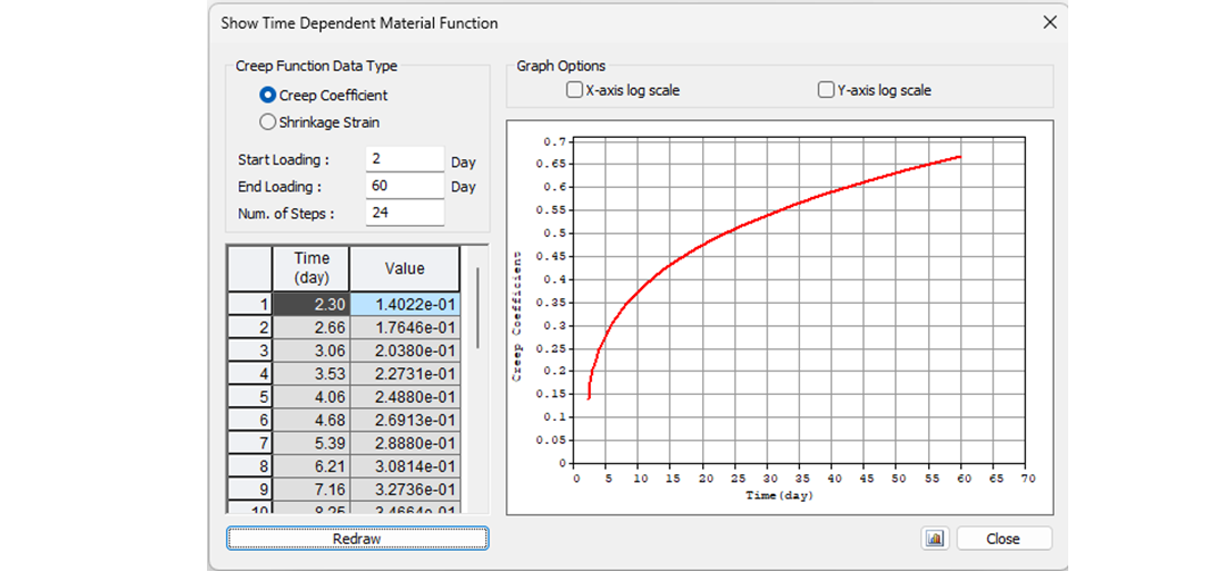
- Creep coefficient for the time from 2 days to 60 days
- Estimation of long-term losses for the time from 2 days to 60 days
Let's start with the creep coefficient. In the following figure, you can see the creep function from 2 to 60 days for concrete grade C45/55 and cement class R according to the Eurocode. The value of the creep coefficient is then φpres ≈ φ(60) - φ(2) = 0.65 - 0.15 = 0.50
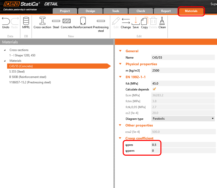
In the Detail application, the creep coefficient can be set in Materials & models. It is obvious that the modulus of elasticity has to be set as the default Ecm value (recall the Increment chapter and the chart in it). You will also notice that the value of φperm = 0.0, which is because we want to apply permanent loads as short-time loads as well as variable loads.
Now it is time for the long-term losses. Of course, you can estimate them (my estimation would be 10%). It is the easiest way, but in our example, we want to do it precisely. So we calculated σ60 - Stress after long-term losses in 60 days (blue line) in the Beam application by setting the final time to 60 days.
The value of σ60 = 1200 MPa as can be seen in the following figure (blue line).
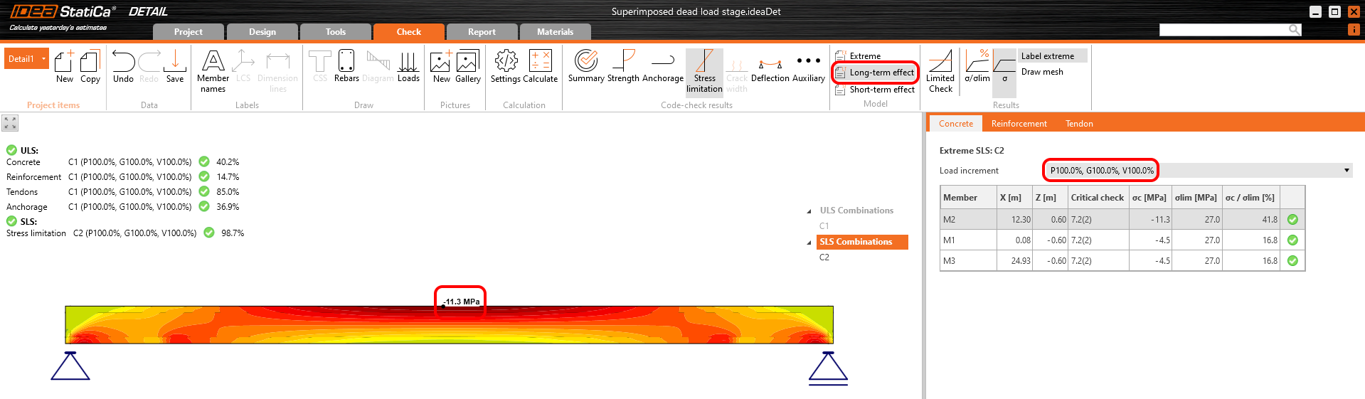
Then we need to calculate the model in the Detail application with the creep coefficient set and with zero long-term losses for the first increment - P100% to determine σdet,60. The important thing is that we need to read the results for long-term effects to have the creep coefficient included.
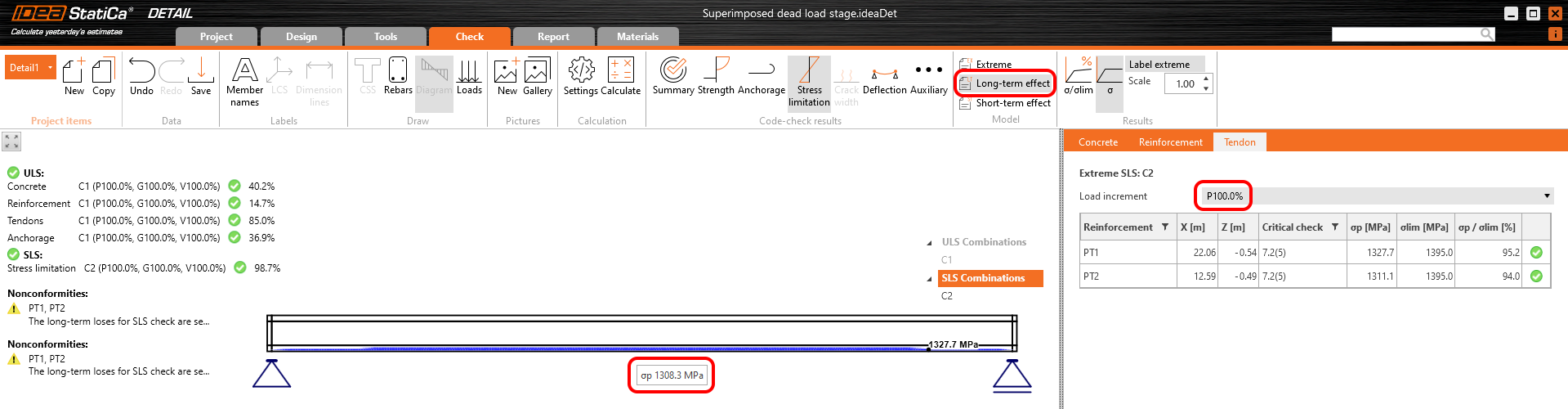
In the figure, we can see that σdet,60 = 1308.5 MPa.
The long-term losses can then be calculated as σ60 / σdet,60 = 1200 / 1308.5 = 0.91 -> long-term loss is 9%. Let's input the value and compare the results.
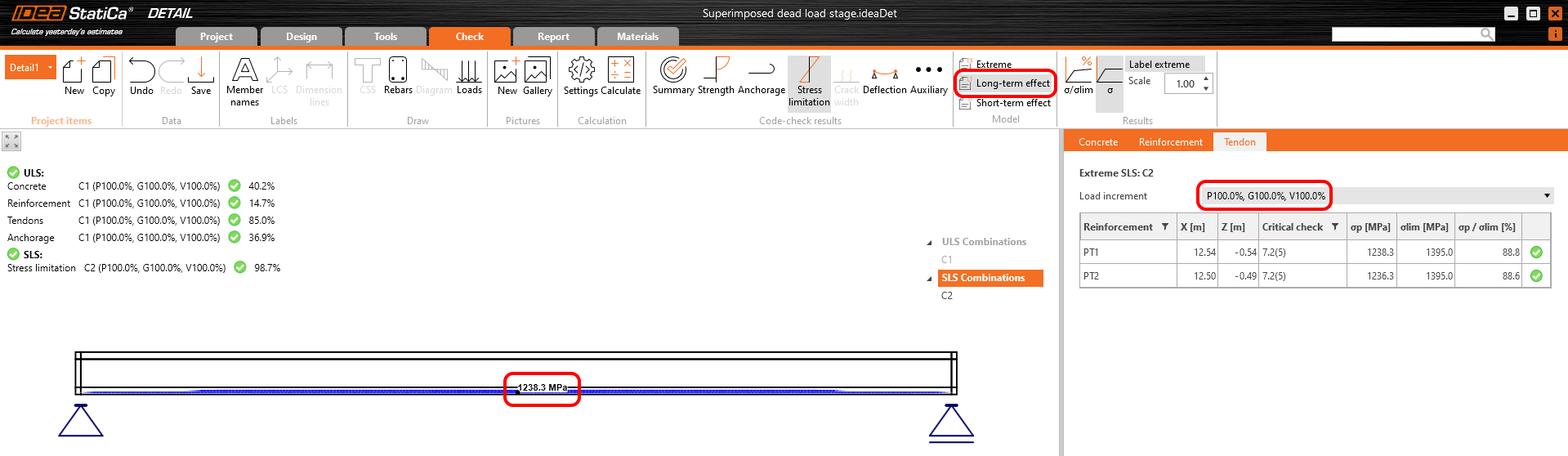
The results are read for long-term losses (we want to have creep and losses included) and for all increments (we want to have all loads included).
Stress in tendons in SLS:
Stress in concrete in SLS:
The SLS section check from the Beam application:
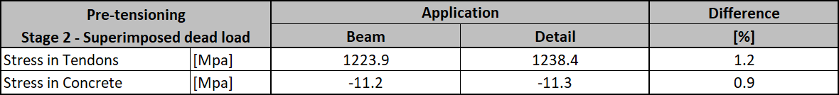
Again, there is a good match. So, it seems we have done the input for this stage correctly. For ULS there will be the same issue described in the previous stage. Note that the coefficients rinf and rsup defined in EN 1992-1-1; 5.10.9 (1) was set as 1.0 in the Beam application.
Now recall the beginning of this article where the increments were described. In the Detail application model for this stage, you can go through the individual increments to see the influence of individual load cases. You can also check the short-term effects which will differ from the previous Detail application model for the transfer of prestressing stage. The reason is the different modulus of elasticity Ecm used in these models.
What you can actually see in the model for the superimposed dead load stage in short-term effects is a transfer of prestressing stage where t=28 days. So, if you don't need to prestress the beam before 28 days you don't need to create a special model for the design of prestressed concrete beams in the transfer of prestressing stage.
End of design working life
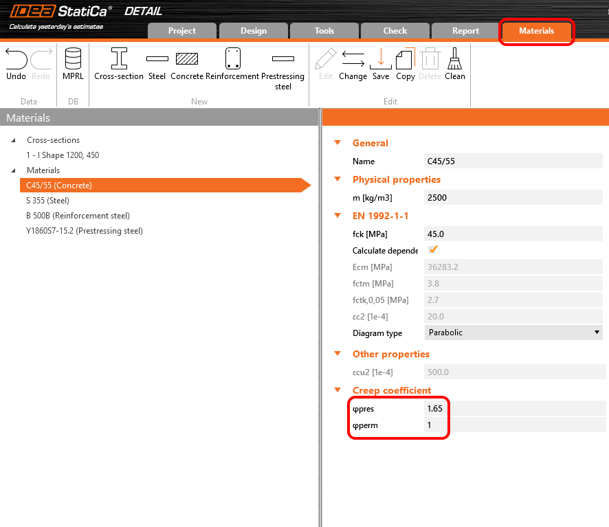
The approach will be the same as for the previous stage. First, we need to determine creep coefficients. In the following figure, you can see the creep coefficient function.
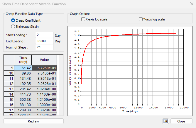
The value φpres ≈ 1.65 for the time from 2 to 18250 days for cement class R according to the Eurocode. The value φperm = φ(18250) - φ(60) ≈ 1.65 - 0.65 = 1.00 for the time from 60 to 18250 days. Note the highlighted value φ(60) in the table above.
Secondly, we need long-term losses. Again, we used the same approach, we calculated the model in the Detail application with the creep coefficients set and with zero long-term losses for the first increment - P100%. The important thing is that we need to read the results for long-term losses to have the creep coefficient included.
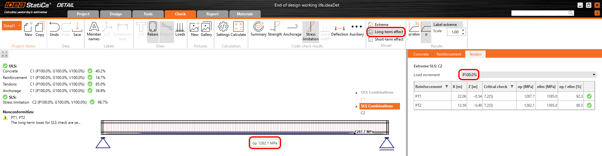
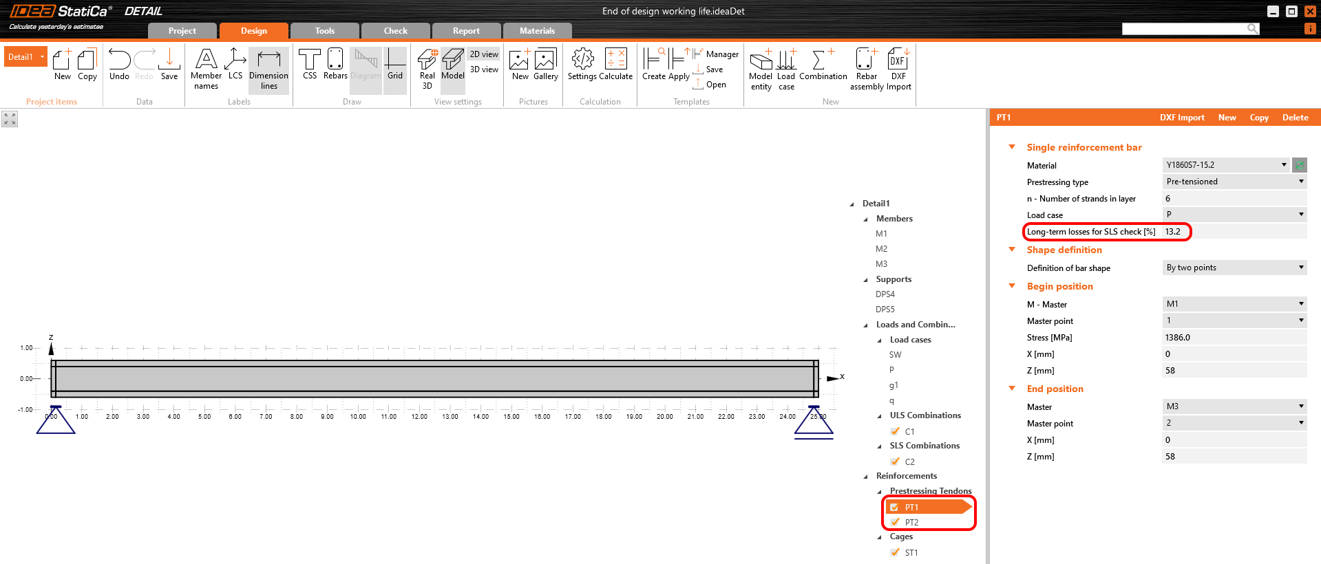
The long-term losses can be calculated as σ∞ / σdet,∞ = 1100 / 1267 = 0.868 -> long-term loss is 13.2%. The value of σ∞ is determined in The beam parameters chapter in the Tendon Stress/Losses chart. Let's input the value and compare the results.
Stress in tendons in SLS:
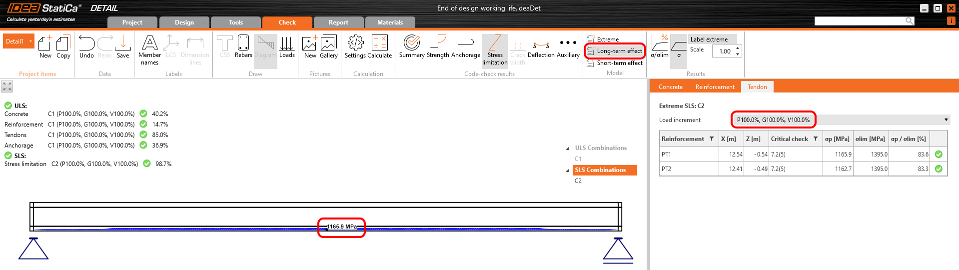
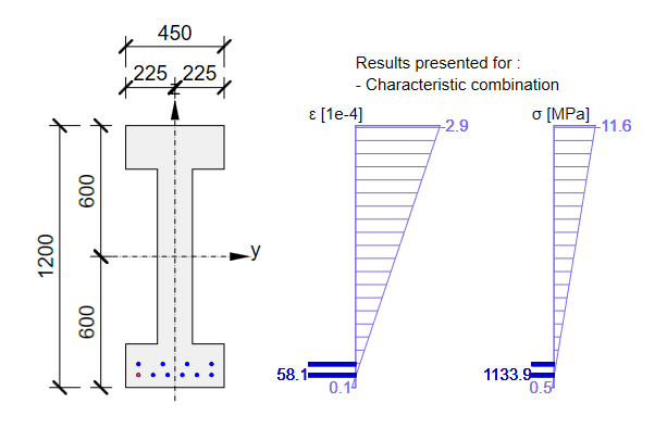
Stress in concrete in SLS:
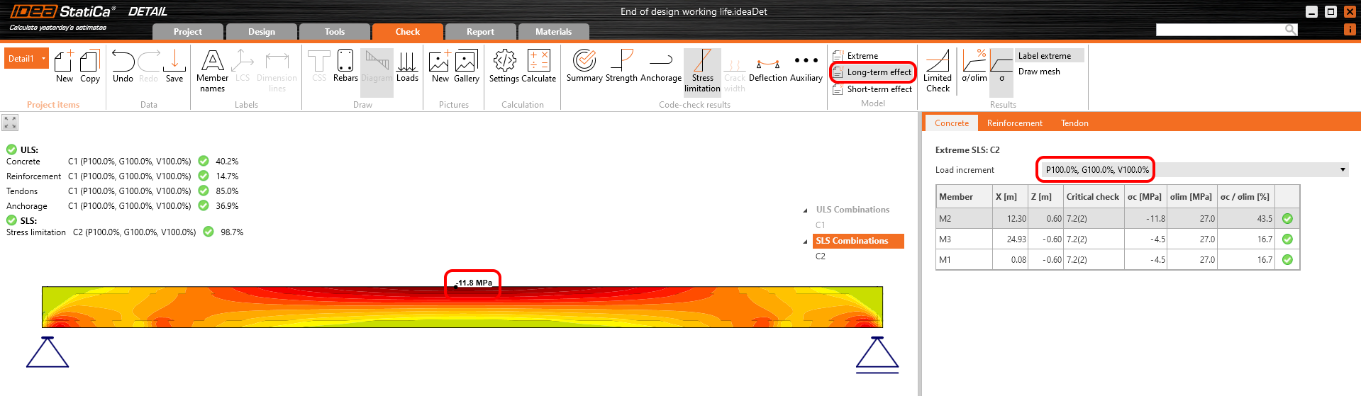
The SLS section check from Beam:

Conclusion
Finally, here is a simple workflow, where you can find the above-described procedure of designing the prestressed concrete structures in the Detail application using pre-tensioned tendons.
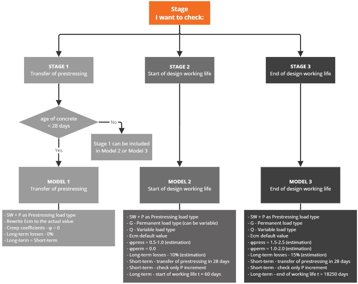
It's worth repeating that for pre-tensioned strands the stress just after release (but before the loss due to immediate elastic concrete strain) has to be input. An estimate of the long-term losses due to shrinkage and relaxation should be input. Creep losses are calculated automatically.
It follows from the preceding that for Model 2 and Model 3 for short-term effects, only the first increment P needs to be considered (since no other permanent loads, nor variable loads will be applied during applying prestressing). It is valid only if the age of concrete when applying prestressing is greater than 28 days, otherwise, you have to do a special model for Stage 1 (for short-term effects).
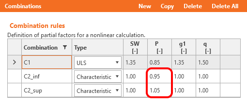
Long-term losses for ULS have to be set as a combination factor. The estimation of long-term losses which can be set in reinforcement is taken into account only for SLS checks. The input for the estimation of 15% should look like this:
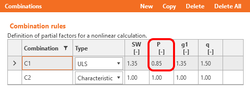
Coefficients rinf and rsup defined in EN 1992-1-1; 5.10.9 (1) for prestressing effects for SLS should be also taken into account in combinations. It means you should create at least two combinations. See the figure.
Read about the implementation of these coefficients in the Beam application in How the rinf and rsup coefficients are taken into account for SLS checks
You have read how to use IDEA StatiCa Detail a concrete design software where you can, among other things, do a design of prestressed concrete beams with discontinuities. But let's not forget about the IDEA StatiCa Beam, which is used for concrete beam design including TDA, and which we used for comparing the results.
Csatolt letöltések
- BEAM model.ideaBeam (IDEABEAM, 959 kB)
- Transfer of prestressing stage.ideaDet (IDEADET, 13 kB)
- Superimposed dead load stage.ideaDet (IDEADET, 15 kB)
- End of design working life.ideaDet (IDEADET, 15 kB)