Prestressing in Detail - Model description
Introduction and material models
The Compatible Stress Field Method (CSFM) is a computational method based on 2D plane stresses in which concrete is modelled using 2D finite elements to which 1D reinforcement elements are connected by constraints. There can be also special types of 1D elements representing bonded prestressing reinforcement added to the model, which can be modelled as pre-tensioned and post-tensioned.
Prestressed reinforcement is modelled similarly to conventional reinforcement using linear elements transmitting the axial force. Each individual prestressed reinforcement element is characterised by its area and material properties. These properties are given by the characteristic material curve according to the used code (EN 1992-1-1, ACI 318-19, etc.)
EUROCODE
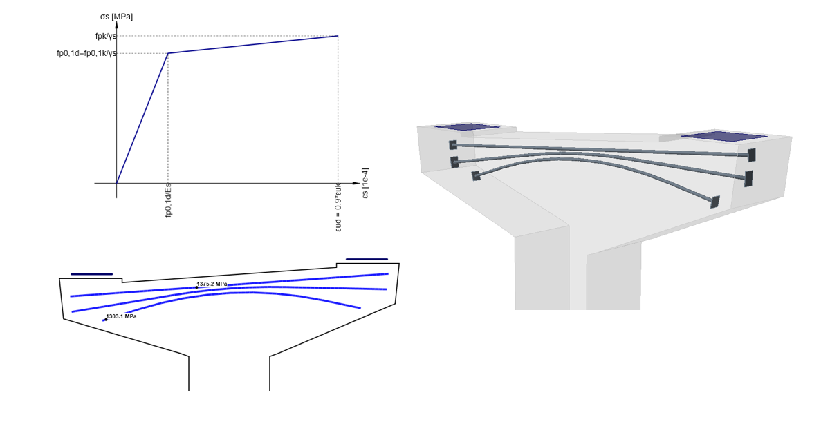
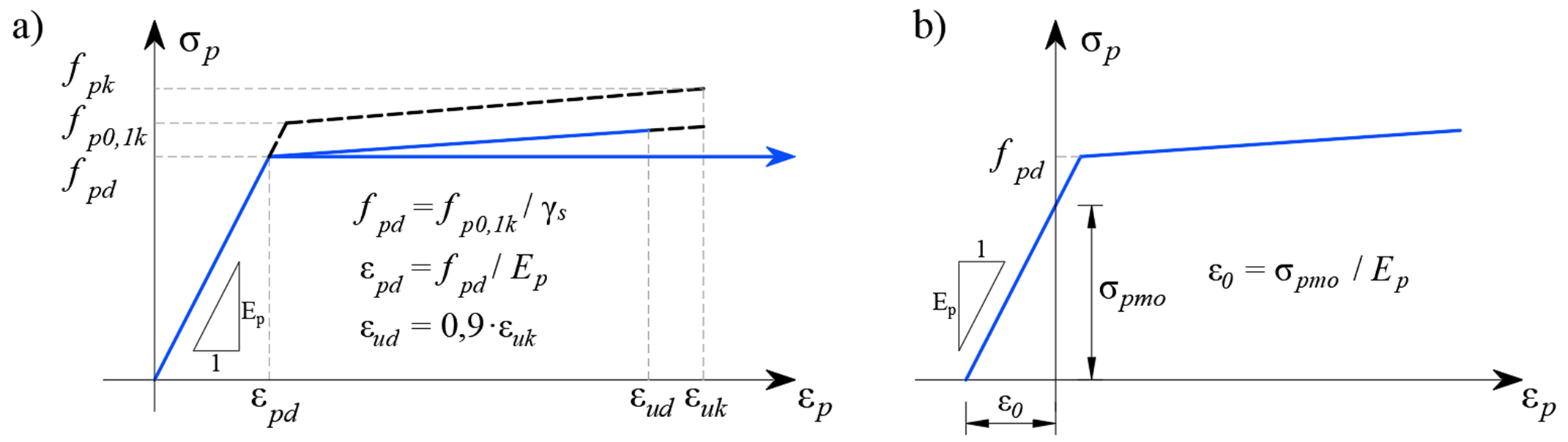
Stress-strain diagram of prestressing reinforcement: a) Stress-strain diagram as defined in EN 1992-1-1; b) initial strain for pre-tensioned reinforcement
ACI
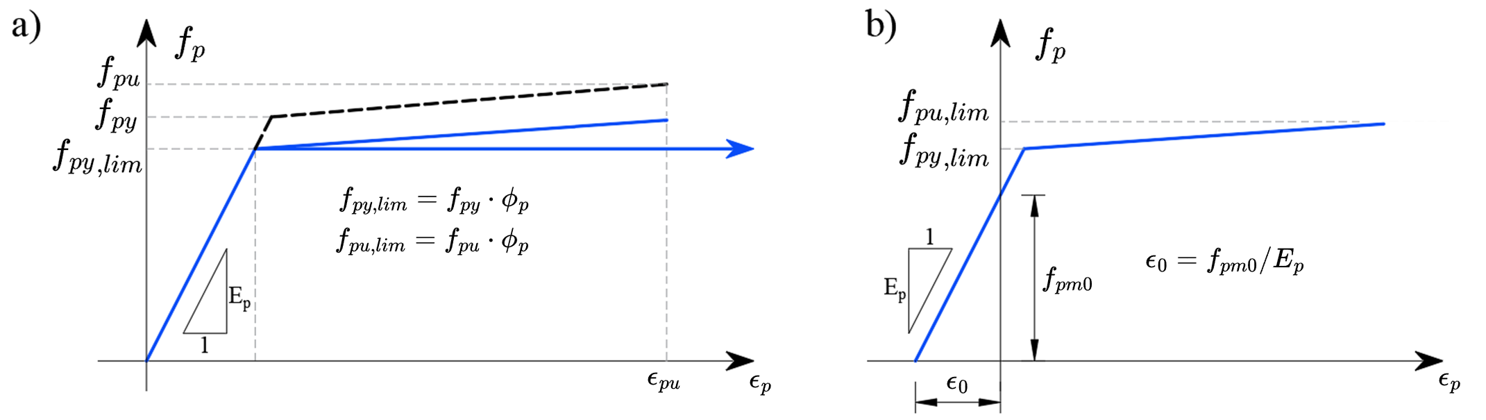
Stress-strain diagram of prestressing reinforcement: a) Stress-strain diagram; b) initial strain for pre-tensioned reinforcement
The reinforcement elements are connected by a bond model to the 2D elements of the concrete model in the same way as the classical concrete reinforcement.
- Read Finite element types
The bond model elements allow the relative deformation of the prestressed reinforcement and the concrete with appropriate nonlinear characteristics. This correctly models the cohesion of the reinforcement with the concrete and also the anchorage model of the pre-tensioned reinforcement. The end modifications of the post-tensioned reinforcement e.g., the anchor plate, are modelled by an element with a stiffness corresponding to the anchor at the end of the prestressing reinforcement, and the end prestressing force is applied as an area load into the concrete model over an area of the anchoring plate size. The model cannot correctly describe the local triaxial stress in the sub-anchor region, and this region must be considered separately.
The tension stiffening of the reinforcement due to concrete interactions is not considered in the prestressing reinforcement because the concrete in the vicinity of the prestressing reinforcement is assumed to be in compression.
Pre-tensioned reinforcement
The pre-tensioned reinforcement is prestressed before the casting of the element, the prestressing reinforcement is almost always routed as a straight line, therefore no frictional prestressing losses occur. Once the required concrete strength is reached, the reinforcement is released from the anchor blocks, thus activating the prestressed reinforcement and transferring the forces from the reinforcement to the concrete. This effect is physically equivalent to the subcooling of the reinforcement and is modelled by an initial strain similar to that of thermal loading. This gives a stress-strain diagram of prestressed reinforcement as shown in the figure above in b). The computational model automatically calculates the deformation response of the structure to the applied prestress, and therefore directly determines the prestress losses by elastic strain of the element.
Since the prestressing force is known, and therefore also the prestressing stress σpmo, the material diagram of the reinforcement is used for the stress dependence on the deformation and can be written as:
\[{{σ}_{p}}=~{{f}}({{ε}}-{{ε}_{0}})\]
Assuming that the prestress in the reinforcement is lower than the yield strength (i.e. the conditions defined in EN 1992-1-1, chapter 5.10.3 are fulfilled), the initial deformation can also be calculated as:
\[{{ε}_{0}}=\frac{{{σ}_{pm0}}}{{{E}_{p}}}\]
ε0 - initial strain from prestressing
σpm0 - stress just before release
Ep - modulus of elasticity for restressing reinforcement
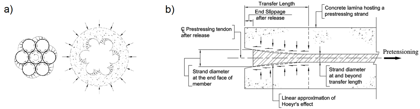
Pre-tensioned reinforcement is specific in that its anchoring of the ends is accomplished by several different mechanisms - adhesion of the reinforcement and concrete at the molecular level, the friction generated at the interface between the surface of the reinforcement and concrete, mechanical pushing of the spiral reinforcement into the concrete, and an increase in the diameter of the prestressing reinforcement known as the wedge mechanism or Hoyer effect. The aforementioned effects are included in the CSFM computational model by modifying the properties of the anchorage model in the end region of the pre-tensioned reinforcement.
Interaction of pre-tensioned reinforcement and concrete: a) spiral reinforcement pushing into concrete; b) Hoyer effect
Post-tensioned reinforcement
The post-tensioned reinforcement is prestressed after the structure has been cast. The prestressing device is supported directly in the structure, thus eliminating the losses due to the elastic strain of the structure from prestressing. Once the desired prestressing force is achieved, the reinforcement is anchored, and then the cable ducts are grouted, thereby achieving a reinforcement bond with the structure. When modelling post-tensioned reinforcement, the calculation is therefore divided into several loading steps - prestressing, application of other permanent loads and application of variable loads.
Finite-element concrete mesh with attached 1D prestressing reinforcement elements:
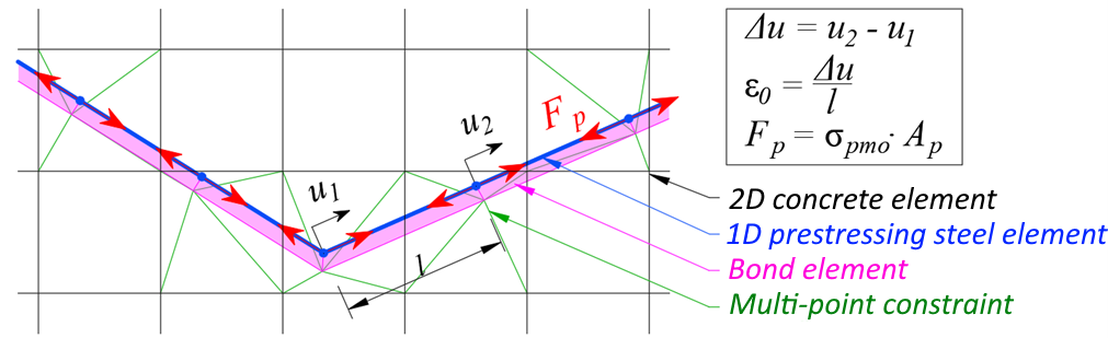
Load step "prestressing"
When prestressing the reinforcement, the stiffness of the reinforcement is not incorporated into the stiffness of the structure. In this loading step, the stiffness of the linear element is not considered in the model, the reinforcement elements are replaced by a substitute load corresponding to the prestressing stress and reinforcement area as shown in the figure above. After reaching the full load from the prestress and convergence of this loading step, the deformation of the specific linear element is read off, based on the deformation the initial strain ε0 of the individual linear elements of the prestressing reinforcement is determined.
The prestressing stress can be defined manually along the length of the reinforcement or calculated automatically based on the geometry of the reinforcement. If the automatic calculation of losses is chosen, frictional loss (according to EN 1992-1-1, 5.10.5.2, or ACI 318-19, 20.3.2) and reinforcement slip (pressing of anchor wedges) during anchoring are considered. As all prestressing reinforcement is applied in one step, loss by successive prestressing is not considered.
Subsequent loading steps with prestressing reinforcement engaged
In the following loading steps (application of other permanent and variable loads) the same procedure is followed as for pre-tensioned reinforcement. The full stiffness of the prestressed reinforcement is considered, the bond between the reinforcement and the surrounding concrete is considered, and the stress-strain diagram of the prestressed reinforcement is modified by the initial strain ε0. This strain is different for each element and was obtained from the previous loading step "prestressing". Due to the bond of the reinforcement and the concrete, the change of prestress due to the elastic deformation of the structure from the external load is correctly considered in the model.