Uniones empalmadas atornilladas de perfil de ala ancha (AISC)
Este ejemplo de verificación fue elaborado por Mark D. Denavit y Kayla Truman-Jarrell en un proyecto conjunto de The University of Tennessee e IDEA StatiCa.
1 Descripción
En este estudio se presenta una comparación entre los resultados del método de los elementos finitos basado en componentes (CBFEM) y los métodos de cálculo tradicionales utilizados en la práctica en EE. UU. para uniones empalmadas atornilladas de perfil de ala ancha (Fig. 1).

Fig. 1 Esquema de la unión empalmada atornillada de perfil de ala ancha estudiada en este trabajo
Los métodos de cálculo tradicionales empleados en este trabajo se basan en los requisitos de diseño por factores de carga y resistencia (LRFD) de la Specification de AISC (2016). Los estados límite evaluados en los cálculos tradicionales incluyen rotura por cortante, aplastamiento y desgarro para la resistencia de los tornillos; plastificación a tracción, rotura a tracción, rotura por desgarro en bloque y plastificación a compresión para la resistencia de las placas de empalme; y plastificación a tracción, rotura a tracción, plastificación a compresión y plastificación a flexión para los elementos de ala ancha. Se consideró que la deformación en el agujero del tornillo bajo carga de servicio es un criterio de diseño. El deslizamiento se evaluó en algunas uniones.
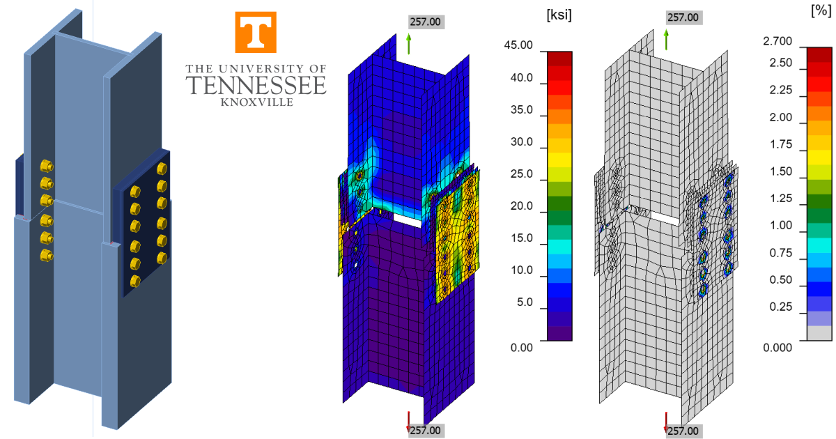
Los resultados del CBFEM se obtuvieron con IDEA StatiCa versión 22.1. En la Fig. 2 se muestran modelos de ejemplo. Las cargas máximas admisibles se determinaron de forma iterativa ajustando la carga aplicada a un valor que el programa considera seguro, pero que si se incrementa en una pequeña cantidad (p. ej., 1 kip) el programa consideraría inseguro.
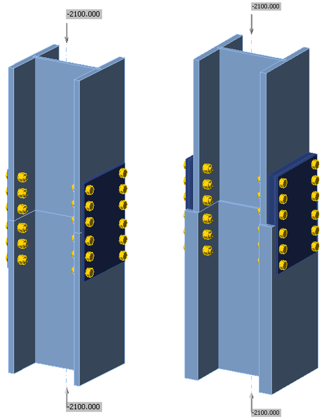
Fig. 2 Uniones empalmadas atornilladas de perfil de ala ancha modeladas en IDEA StatiCa.
En las comparaciones presentadas en este estudio, el pilar superior fue siempre un W14×159 y el pilar inferior fue un W14×159 o un W14×370. Se asumió que todos los perfiles de ala ancha cumplen con ASTM A992 (Fy = 50 ksi, Fu = 65 ksi). La unión de empalme se basó en la Tabla 14-3 del Manual de AISC (2017). Se utilizaron un total de 24 tornillos A490 de 7/8 in. de diámetro (roscas no excluidas de los planos de cortante) en la unión (6 para cada una de las uniones de la placa de empalme con el ala del pilar). La unión no era resistente al deslizamiento, salvo que se indique lo contrario. No había separación entre los pilares. Las uniones se evaluaron tanto considerando el apoyo por contacto (Muir 2015) como sin considerarlo. La separación entre tornillos fue s = 3 in. y las distancias al borde vertical fueron lev1 = 1,5 in. y lev2 = 1,75 in., con una longitud total de 18,5 in. para la placa de empalme. La placa de empalme tenía 14 in. de ancho. El intereje de tornillos fue g = 11,5 in. y la distancia horizontal al borde fue leh = 1,25 in. en algunos casos, según lo recomendado por la Tabla 14-3. En otros casos, el intereje de tornillos fue g = 8 in. y la distancia horizontal al borde fue leh = 3 in. para evitar la rotura por desgarro en bloque. El espesor de la placa de empalme varió en el análisis. La Tabla 14-3 recomienda un espesor de placa de 0,5 in. para pilares W14×159. Se asumió que las placas de empalme cumplen con ASTM A36 (Fy = 36 ksi, Fu = 58 ksi).
Este diseño de empalme de pilar es más adecuado para conectar dos pilares cargados axialmente mediante apoyo por contacto. Este estudio investiga casos en los que se desprecia el apoyo por contacto, así como casos en los que los pilares están cargados a tracción o con flexión combinada en el eje principal. Se utilizó la misma unión de empalme a lo largo del estudio para uniformidad y facilidad de comparación; sin embargo, distintas uniones serían probablemente más eficientes para casos con tracción significativa o flexión combinada.
2 Carga axial
En primer lugar, se investigó la resistencia de la unión bajo carga axial para el caso de pilares de igual canto e intereje de tornillos g = 11,5 in. En la Fig. 3 se presenta la variación de la carga máxima de compresión axial aplicada en función del espesor de la placa de empalme. La resistencia de la unión es mucho mayor con apoyo por contacto que sin él. Con apoyo por contacto, el límite de deformación plástica en el alma del pilar fue determinante para IDEA StatiCa, y la plastificación a compresión del pilar fue determinante para los cálculos tradicionales. Los tornillos y las placas de empalme están esencialmente sin tensión en estos análisis; por lo tanto, la resistencia no varió con el espesor de la placa de empalme. IDEA StatiCa proporciona una carga máxima admisible aproximadamente un 4% mayor que los cálculos tradicionales, principalmente debido a la pequeña cantidad de endurecimiento por deformación asumida en el modelo y a pequeñas diferencias en el área de la sección transversal del perfil de ala ancha (es decir, IDEA StatiCa no modela los acuerdos y una parte del área en cada intersección del alma y el ala se contabiliza dos veces).
Sin apoyo por contacto, la carga se transfiere de un perfil de ala ancha al otro a través de los tornillos y las placas de empalme. Para la placa de empalme más delgada (es decir, 3/8 in.), el límite de deformación plástica en la placa de empalme fue determinante para IDEA StatiCa, y la plastificación a compresión de la placa de empalme fue determinante para los cálculos tradicionales. Nótese que Lc/r ≤ 25 para la placa de empalme cuando el factor de longitud efectiva se toma como 0,65 para una condición empotrado-empotrado, por lo que no se aplicó reducción por estabilidad. La carga máxima aplicada fue de 309 kips para IDEA StatiCa y de 340 kips para los cálculos tradicionales. IDEA StatiCa proporciona una carga máxima aplicada menor porque la tensión en la placa de empalme se concentra cerca de los agujeros de los tornillos. Para todos los demás espesores de placa de empalme, la rotura por cortante de los tornillos fue determinante tanto para IDEA StatiCa como para los cálculos tradicionales, y la carga máxima aplicada fue idéntica.
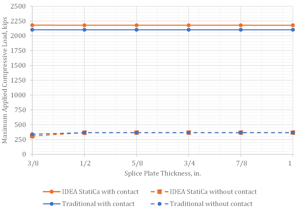
Fig. 3 Carga máxima de compresión aplicada frente al espesor de la placa de empalme
En la Fig. 4 se presenta la variación de la carga máxima de tracción axial aplicada en función del espesor de la placa de empalme. Los análisis de IDEA StatiCa se realizaron con y sin operaciones de contacto por apoyo; sin embargo, los resultados de ambos casos fueron idénticos. La rigidez de contacto a tracción es despreciable.
Para las uniones con placas de empalme más gruesas (5/8 in. de espesor o más), la rotura por cortante de los tornillos fue determinante tanto para IDEA StatiCa como para los cálculos tradicionales. La carga máxima aplicada fue la misma para ambos métodos. Para las uniones con placas de empalme más delgadas, el desgarro controló la resistencia según IDEA StatiCa, y la rotura por desgarro en bloque de la placa de empalme controló la resistencia según los cálculos tradicionales. La discrepancia en los estados límite determinantes se resuelve refinando la malla en IDEA StatiCa. Para la unión con placas de empalme de 1/2 in. de espesor y la malla por defecto (tamaño máximo de malla de 1,969 in.), el desgarro controla con una carga máxima de tracción aplicada de 341 kips. Para un tamaño máximo de malla de 1 in., el límite de deformación plástica se alcanza en las placas de empalme con una carga aplicada de 338 kips. Un refinamiento adicional hasta un tamaño máximo de malla de 0,25 in. produce una carga máxima aplicada de 328 kips, siendo la deformación plástica de las placas de empalme el criterio determinante. El patrón de deformación plástica para esta unión es coherente con un fallo por rotura en bloque por desgarro (Fig. 5). Incluso con la malla refinada, IDEA StatiCa proporciona una carga máxima aplicada mayor que los cálculos tradicionales. Para la unión con placas de empalme de 1/2 in. de espesor, la carga máxima aplicada según los cálculos tradicionales es de 308 kips.
Investigadores han señalado que las disposiciones sobre rotura por desgarro en bloque de la Specification de AISC (2016) pueden ser conservadoras en comparación con datos de ensayos físicos, y han propuesto ecuaciones alternativas para predecir mejor la resistencia a la rotura por desgarro en bloque (Teh y Deierlein 2017). Su ecuación propuesta para la resistencia nominal a la rotura por desgarro en bloque, Rn = FuAnt + 0,6FuAev, utiliza un área de cortante efectiva, Aev, igual a la media de las áreas de cortante bruta y neta actualmente utilizadas en la Specification de AISC (es decir, Aev = (Agv + Anv)/2). La resistencia disponible a la rotura por desgarro en bloque para la unión con placas de empalme de 1/2 in. de espesor utilizando esta ecuación es de 391 kips, por lo que otros estados límite serían determinantes. Si la ecuación propuesta por Teh y Deierlein (2017) es precisa, los resultados de IDEA StatiCa serían conservadores.

Fig. 4 Carga máxima de tracción aplicada frente al espesor de la placa de empalme
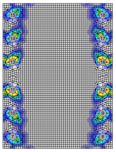
Fig. 5 Deformación plástica en la placa de empalme con una carga aplicada de 328 kips para la unión con placa de empalme de 1/2 in. de espesor y tamaño máximo de malla de 0,25 in.
Para explorar más el comportamiento de esta unión bajo carga de tracción, el análisis se repitió utilizando un intereje de tornillos de g = 8 in. La rotura por desgarro en bloque no controla la resistencia a tracción de la placa de empalme con este valor de g. En la Fig. 6 se presenta la variación de la carga máxima de tracción axial aplicada en función del espesor de la placa de empalme para este caso. Los resultados de IDEA StatiCa son esencialmente los mismos que para el caso con el intereje de tornillos mayor. Para IDEA StatiCa y las uniones con las dos placas de empalme más delgadas (es decir, 3/8 in. y 1/2 in.), el estado límite determinante fue el desgarro, alcanzando únicamente los tornillos en los extremos del empalme el 100% de utilización (Fig. 7). La rotura por cortante de los tornillos fue determinante para las demás uniones en IDEA StatiCa, con todos los tornillos alcanzando el 100% de utilización. Para los cálculos tradicionales, la resistencia del grupo de tornillos fue determinante en todos los casos. Sin embargo, la carga máxima aplicada en los cálculos tradicionales fue mayor que en IDEA StatiCa para las uniones con las dos placas de empalme más delgadas. En los cálculos tradicionales, la resistencia efectiva de cada tornillo del grupo se evalúa y se suma para obtener la resistencia del grupo de tornillos. Por lo tanto, algunos tornillos están controlados por desgarro mientras que otros lo están por rotura a cortante, pero todos contribuyen con su resistencia máxima al grupo de tornillos. En IDEA StatiCa, todos los tornillos se modelan con la misma rigidez, por lo que todos experimentan aproximadamente la misma carga en esta unión. Para las placas más delgadas, el desgarro controla la resistencia de los tornillos extremos y estos alcanzan su resistencia antes de que los tornillos restantes puedan alcanzar la suya. Esto es análogo al método del tornillo crítico, que se utiliza más habitualmente para grupos de tornillos con carga excéntrica en los cálculos tradicionales. La aplicación del método del tornillo crítico en este caso produce resultados de resistencia más similares a los de IDEA StatiCa.

Fig. 6 Carga máxima de tracción aplicada frente al espesor de la placa de empalme (intereje de tornillos, g = 8 in.)

Fig. 7 Representación de la utilización de los tornillos con una carga aplicada de 256 kips para la unión con placa de empalme de 3/8 in. de espesor
3 Carga axial con pilares de distinto canto
Cuando los pilares a conectar tienen cantos diferentes, se utilizan placas de relleno para compensar el canto del pilar menor y crear una superficie nivelada para las placas de empalme. Las placas de relleno pueden ser desarrolladas o no desarrolladas. Las placas de relleno desarrolladas tienen fijación adicional al pilar más allá de las placas de empalme. Las placas de relleno no desarrolladas no tienen fijación adicional. La Specification de AISC (2016) exige reducciones en la resistencia a cortante y al deslizamiento para uniones atornilladas con rellenos no desarrollados.
Los resultados presentados en esta sección corresponden a una unión de empalme con un pilar superior W14×159 y un pilar inferior W14×370. La diferencia de canto entre estas dos secciones es de 2,90 in.; por lo tanto, se asumió que el espesor total de las placas de relleno era de 1,45 in., lo que se consiguió con dos capas, una de 1-1/4 in. de espesor y otra de 3/16 in. de espesor.
En la Fig. 8 se presenta la variación de la carga máxima de compresión axial aplicada en función del espesor de la placa de empalme. El intereje de tornillos se tomó como g = 11,5 in. para este caso, como sería habitual en un empalme de pilar. Con apoyo por contacto, los resultados son esencialmente los mismos que para el caso con pilares de igual canto y sin rellenos. Nótese, sin embargo, que el contacto se definió tanto entre el perfil de ala ancha superior y el inferior como entre las placas de relleno y el perfil de ala ancha inferior. Si el contacto se definía únicamente entre los dos elementos de ala ancha, el descentramiento de los ejes de las alas producía flexión del ala (Fig. 9) y resistencias algo reducidas en IDEA StatiCa (1879 kips sin contacto de las placas de relleno frente a 2121 kips con contacto de las placas de relleno para la unión con placas de empalme de 1/2 in. de espesor). Se alcanza el apoyo por contacto completo dado que los dos pilares pertenecen a la misma familia (es decir, W14) y la distancia entre alas es la misma, por lo que los cálculos tradicionales no se ven afectados.
Sin apoyo por contacto, la resistencia del empalme es mucho menor e IDEA StatiCa muestra exactamente la misma resistencia que los cálculos tradicionales para todas las uniones excepto para la de las placas de empalme más delgadas (es decir, 3/8 in. de espesor). Nótese que la reducción de la resistencia a cortante para rellenos definida en la Sección J5.2 de la Specification de AISC (2016) se aplica tanto en IDEA StatiCa como en los cálculos tradicionales. Para la unión con las placas de empalme más delgadas, la deformación plástica en las placas de empalme es determinante en IDEA StatiCa, lo que resulta en una resistencia menor que la de los cálculos tradicionales.

Fig. 8 Carga máxima de compresión aplicada frente al espesor de la placa de empalme para uniones con placas de relleno

Fig. 9 Resultados de deformación plástica con una carga aplicada de 1920 kips para la unión con placa de empalme de 1/2 in. de espesor y sin contacto entre las placas de relleno y el perfil de ala ancha inferior (factor de escala de deformación = 10)
En la Fig. 10 se presenta la variación de la carga máxima de tracción axial aplicada en función del espesor de la placa de empalme. El intereje de tornillos se tomó como g = 8 in. para este caso con el fin de evitar el estado límite de rotura por desgarro en bloque. Al igual que en el caso de compresión, IDEA StatiCa y los cálculos tradicionales proporcionan la misma resistencia para todas las uniones excepto para la de las placas de empalme más delgadas. Para la unión con las placas de empalme más delgadas, el desgarro controla algunos de los tornillos y surge una diferencia de resistencia debido a las distintas formas en que IDEA StatiCa y los cálculos tradicionales tratan los grupos de tornillos con tornillos de diferente resistencia.
También se aplica una reducción de resistencia al estado límite de deslizamiento para uniones con dos o más rellenos entre las partes conectadas. La reducción se define mediante hf, un factor para rellenos, en la Ecuación J3-4 de la Specification de AISC (2016); hf = 0,85 para casos con dos o más rellenos entre las partes conectadas y hf = 1,0 en caso contrario. Si la unión de empalme fuera resistente al deslizamiento, la resistencia disponible sería de 199 kips para el caso sin rellenos o con rellenos de una sola capa, y de 169 kips para el caso con rellenos de varias capas. Sin apoyo por contacto y definiendo la unión como resistente al deslizamiento, la carga axial máxima aplicada a tracción según IDEA StatiCa es de 152 kips para la unión con rellenos y placas de empalme de 1/2 in. de espesor. IDEA StatiCa detecta los rellenos múltiples y aplica el factor correspondiente para rellenos. La menor resistencia obtenida con IDEA StatiCa se debe a que este programa considera la carga excéntrica de las placas de relleno, que es resistida por un par formado por la presión de contacto y la tracción en los tornillos (Fig. 11). IDEA StatiCa desprecia de forma conservadora la fricción debida a la presión de contacto, teniendo en cuenta la tracción aplicada en el tornillo mediante el factor de reducción ksc. (Specification de AISC (2016), Sección J3.9).
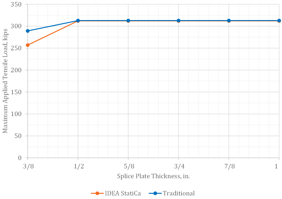
Fig. 10 Carga máxima de tracción aplicada frente al espesor de la placa de empalme para uniones con placas de relleno

Fig. 11 Resultados de tensión en los contactos y fuerza en los tornillos con una carga de tracción aplicada de 152 kips para la unión con placa de empalme de 1/2 in. de espesor y tornillos de fricción (resistentes al deslizamiento) (factor de escala de deformación = 10)
4 Carga axial combinada con flexión en el eje principal
Las uniones de empalme pueden necesitar soportar más que simples cargas axiales. Para el caso de un momento flector de 1000 kip-in en el eje principal aplicado simultáneamente con la carga axial, la variación de la carga máxima de compresión aplicada en función del espesor de la placa de empalme se presenta en la Fig. 12, y la variación de la carga máxima de tracción aplicada en función del espesor de la placa de empalme se presenta en la Fig. 13. El intereje de tornillos se tomó como g = 8 in. para los análisis de esta sección con el fin de evitar el estado límite de rotura por desgarro en bloque.
A compresión y con apoyo por contacto, la resistencia del elemento fue determinante tanto en los análisis de IDEA StatiCa como en los cálculos tradicionales. Ambas cargas máximas aplicadas se reducen respecto al caso de compresión pura (Fig. 3) debido al momento flector simultáneo. A compresión sin apoyo por contacto y a tracción, IDEA StatiCa proporciona cargas máximas aplicadas ligeramente mayores que los cálculos tradicionales para las uniones con placas de empalme más gruesas, donde la rotura por cortante de los tornillos es determinante. En cambio, IDEA StatiCa y los cálculos tradicionales proporcionaron la misma resistencia bajo carga concéntrica. Para los cálculos tradicionales, la fuerza en cada grupo de tornillos se determinó como P/2 ± M/d, donde d es el canto del perfil de ala ancha (Tamboli 2016). Esta ecuación asume que el cortante en los tornillos es la única fuerza en la superficie de contacto entre el ala del pilar y la placa de empalme. Con el modelado explícito de la unión en IDEA StatiCa, se observa tensión de contacto en las superficies de contacto (Fig. 14), lo que no incrementa directamente la capacidad (ya que la fricción en las superficies de contacto se desprecia en IDEA StatiCa), pero desplaza hacia el exterior el brazo de palanca que resiste el momento y reduce el cortante en los tornillos.
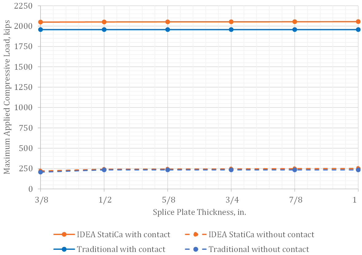
Fig. 12 Carga máxima de compresión aplicada frente al espesor de la placa de empalme para la unión con flexión simultánea en el eje principal

Fig. 13 Carga máxima de tracción aplicada frente al espesor de la placa de empalme para la unión con flexión simultánea en el eje principal
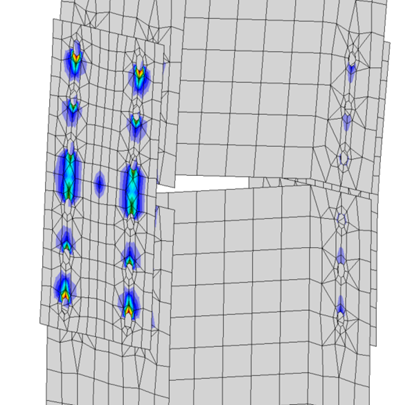
Fig. 14 Tensión en los contactos con una carga de tracción aplicada de 212 kips y un momento en el eje principal aplicado de 1000 kip-in para la unión con placa de empalme de 1/2 in. de espesor (factor de escala de deformación = 10)
La variación de la carga axial máxima aplicada en función del momento en el eje principal aplicado para la unión con placas de empalme de 1/2 in. de espesor, sin apoyo por contacto e intereje de tornillos g = 8 in. se muestra en la Fig. 15. Estos resultados confirman que IDEA StatiCa concuerda bien con los cálculos tradicionales en todo el rango de carga axial aplicada y momento flector para esta unión.

Fig. 15 Carga axial máxima aplicada frente al momento en el eje principal aplicado (compresión negativa)
5 Resumen
Este estudio comparó el diseño de uniones empalmadas atornilladas de perfil de ala ancha utilizando los métodos de cálculo tradicionales empleados en la práctica en EE. UU. e IDEA StatiCa. Las principales observaciones del estudio incluyen:
- La resistencia disponible obtenida con IDEA StatiCa concuerda bien con los cálculos tradicionales.
- Entre las mayores diferencias de resistencia se encontraron las uniones en las que el desgarro controlaba la resistencia de algunos tornillos. IDEA StatiCa alcanzó el 100% de utilización de los tornillos controlados por desgarro mientras que otros tornillos no alcanzaron el 100% de utilización, lo que resultó en comparaciones conservadoras respecto a los cálculos tradicionales, que permiten obtener simultáneamente la resistencia de todos los tornillos de un grupo de tornillos con carga concéntrica.
- IDEA StatiCa proporciona resistencias algo mayores que los cálculos tradicionales cuando la rotura por desgarro en bloque es determinante.
- IDEA StatiCa identificó correctamente todas las uniones de este estudio con placas de relleno no desarrolladas y aplicó posteriormente las reducciones de resistencia a cortante o al deslizamiento de los tornillos definidas en la Specification de AISC (2016). Sin embargo, el algoritmo de IDEA StatiCa para identificar placas de relleno no desarrolladas no cubre todos los casos, y se requiere criterio de ingeniería en casos no estándar para garantizar que los resultados de resistencia se aplican cuando corresponde.
6 Referencias
AISC. (2016). Specification for Structural Steel Buildings. American Institute of Steel Construction, Chicago, Illinois.
AISC. (2017). Steel Construction Manual, 15th Edition. American Institute of Steel Construction, Chicago, Illinois.
Muir, L. (2015). "Bear It and Grin." Modern Steel Construction, (December).
Tamboli, A. (2016). Handbook of Structural Steel Connection Design and Details, Third Edition. McGraw Hill, New York, NY.
Teh, L. H., and Deierlein, G. G. (2017). "Effective Shear Plane Model for Tearout and Block Shear Failure of Bolted Connections." Engineering Journal, AISC, 54(3), 181–194.