Descripción
El objetivo de este capítulo es la verificación del método de los elementos finitos basado en componentes (CBFEM) de perfiles en T conectados con dos tornillos cargados a tracción mediante el método de componentes (CM) y el modelo de elementos finitos de investigación (RM) creado en el software Midas FEA; véase (Gödrich et al. 2019).
Modelo analítico
El perfil en T soldado y el tornillo a tracción son los componentes examinados en el estudio. Ambos componentes se diseñan según EN 1993-1-8:2005. Las soldaduras se diseñan para que no sean el componente más débil. Las longitudes efectivas para fallos circulares y no circulares se consideran según EN 1993-1-8:2005 cl. 6.2.6. Solo se consideran cargas de tracción. Se consideran tres modos de colapso según EN 1993-1-8:2005 cl. 6.2.4.1: 1. modo con plastificación total del ala, 2. modo con dos líneas de plastificación junto al alma y rotura de los tornillos, y 3. modo por rotura de los tornillos; véase Fig. 5.1.1. Los tornillos se diseñan según cl. 3.6.1 en EN 1993-1-8:2005. La resistencia de cálculo considera la resistencia al punzonamiento y la rotura del tornillo.

\[ \textsf{\textit{\footnotesize{Fig. 5.1.1 Collapse modes of T-stub}}}\]
Modelo numérico de cálculo
El perfil en T se modela mediante elementos de lámina de 4 nodos tal como se describe en el Capítulo 3 y se resume a continuación. Cada nodo tiene 6 grados de libertad. Las deformaciones del elemento comprenden contribuciones de membrana y de flexión. El estado del material elastoplástico no lineal se investiga en cada capa del punto de integración. La evaluación se basa en la deformación máxima dada según EN 1993‑1‑5:2006 con un valor del 5 %. Los tornillos se dividen en tres subcomponentes. El primero es el fuste del tornillo, que se modela como un muelle no lineal y solo trabaja a tracción. El segundo subcomponente transmite la fuerza de tracción a los alas. El tercer subcomponente resuelve la transmisión del cortante.
Modelo numérico de investigación
En los casos en que el CBFEM proporciona una resistencia, rigidez inicial o capacidad de deformación mayor, se utiliza el modelo de elementos finitos de investigación (RM) de elementos sólidos validado experimentalmente (Gödrich et al. 2013) para verificar el modelo CBFEM. El RM se crea en el software Midas FEA con elementos sólidos hexaédricos y octaédricos, véase Fig. 5.1.2. Se realizó un estudio de sensibilidad de malla para obtener resultados adecuados en un tiempo razonable. El modelo numérico de los tornillos se basa en el modelo de (Wu et al. 2012). El diámetro nominal se considera en el fuste y el diámetro efectivo del núcleo se considera en la parte roscada. Las arandelas están acopladas con la cabeza y la tuerca. La deformación causada por el deslizamiento de las roscas en la zona de contacto rosca-tuerca se modela mediante elementos de interfaz. Los elementos de interfaz no pueden transferir tensiones de tracción. Entre las arandelas y los alas del perfil en T se utilizan elementos de contacto que permiten la transmisión de presión y fricción. Se modeló un cuarto de la muestra aprovechando la simetría.

\[ \textsf{\textit{\footnotesize{Fig. 5.1.2 Research FEM model}}}\]

\[ \textsf{\textit{\footnotesize{Fig. 5.1.3 Geometry of the T-stubs}}}\]
Rango de validez
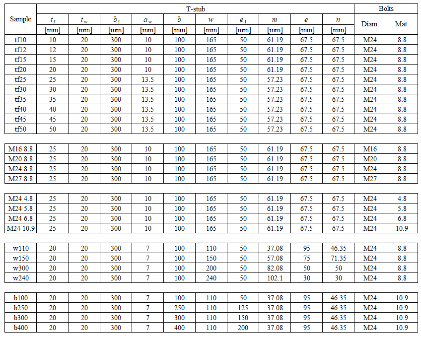
El CBFEM fue verificado para las geometrías típicas seleccionadas de perfiles en T. El espesor mínimo del ala es de 8 mm. La distancia máxima de los tornillos al diámetro del tornillo está limitada por p/db ≤ 20. La distancia de la línea de tornillos al alma está limitada a m/db ≤ 5. El resumen de las muestras consideradas con placas de acero S235: fy = 235 MPa, fu = 360 MPa, E = Ebolt = 210 GPa se muestra en la Tab. 5.1.1 y en la Fig. 5.1.3.
Tab. 5.1.1 Resumen de las muestras consideradas de perfiles en T
Comportamiento global
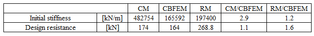
Se preparó una comparación del comportamiento global del perfil en T descrito mediante diagramas fuerza-deformación para todos los procedimientos de cálculo. La atención se centró en las características principales: rigidez inicial, resistencia de cálculo y capacidad de deformación. Se eligió la muestra tf20 como referencia; véase Fig. 5.1.4 y Tab. 5.1.2. El CM generalmente proporciona una rigidez inicial mayor en comparación con el CBFEM y el RM. En todos los casos, el RM proporciona la mayor resistencia de cálculo, como se muestra en el capítulo 6. También se compara la capacidad de deformación. La capacidad de deformación del perfil en T se calculó según (Beg et al. 2004). El RM no considera la fisuración del material, por lo que la predicción de la capacidad de deformación es limitada.

\[ \textsf{\textit{\footnotesize{Fig. 5.1.4 Force–deformation diagram}}}\]
Tab. 5.1.2 Resumen del comportamiento global
Verificación de la resistencia
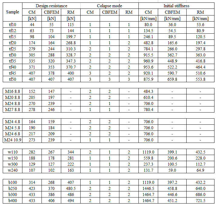
En el siguiente paso, las resistencias de cálculo calculadas por CBFEM se compararon con los resultados del CM y del RM. La comparación también se centró en la capacidad de deformación y la determinación del modo de colapso. Todos los resultados están ordenados en la Tab. 5.1.3. El estudio se realizó para cinco parámetros: espesor del ala, tamaño del tornillo, material del tornillo, separación de tornillos y anchura del perfil en T.
Tab. 5.1.3 Resumen del comportamiento global
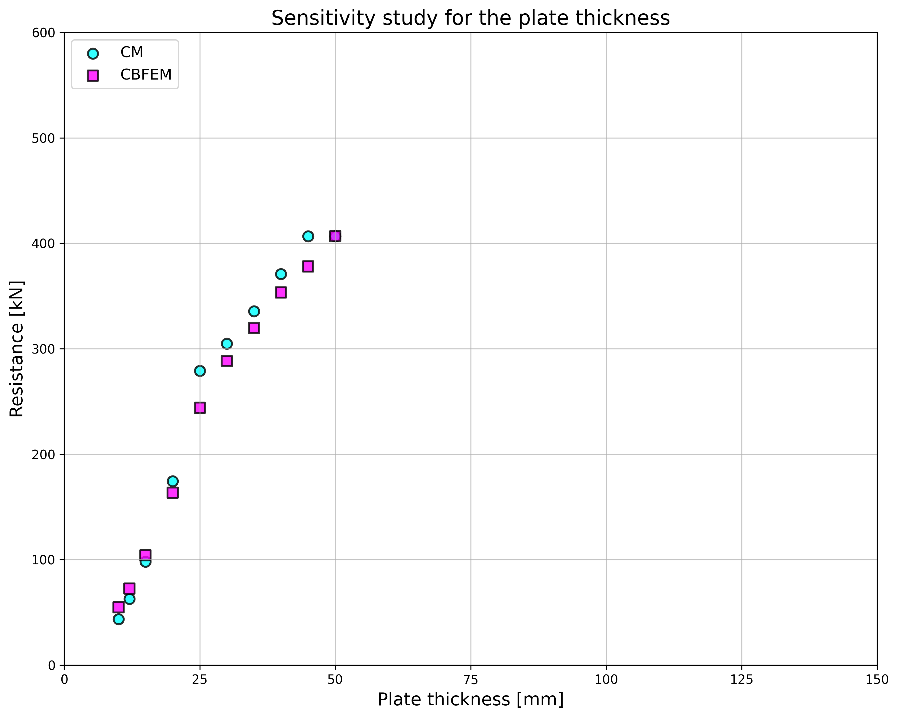
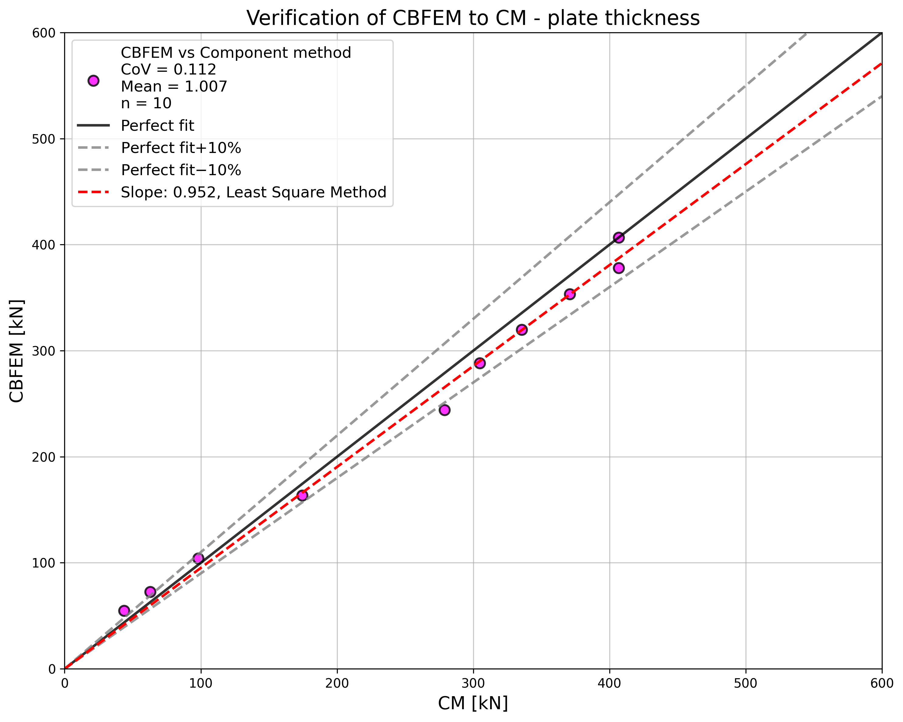
\[ \textsf{\textit{\footnotesize{Fig. 5.1.5 Sensitivity study of flange thickness}}}\]
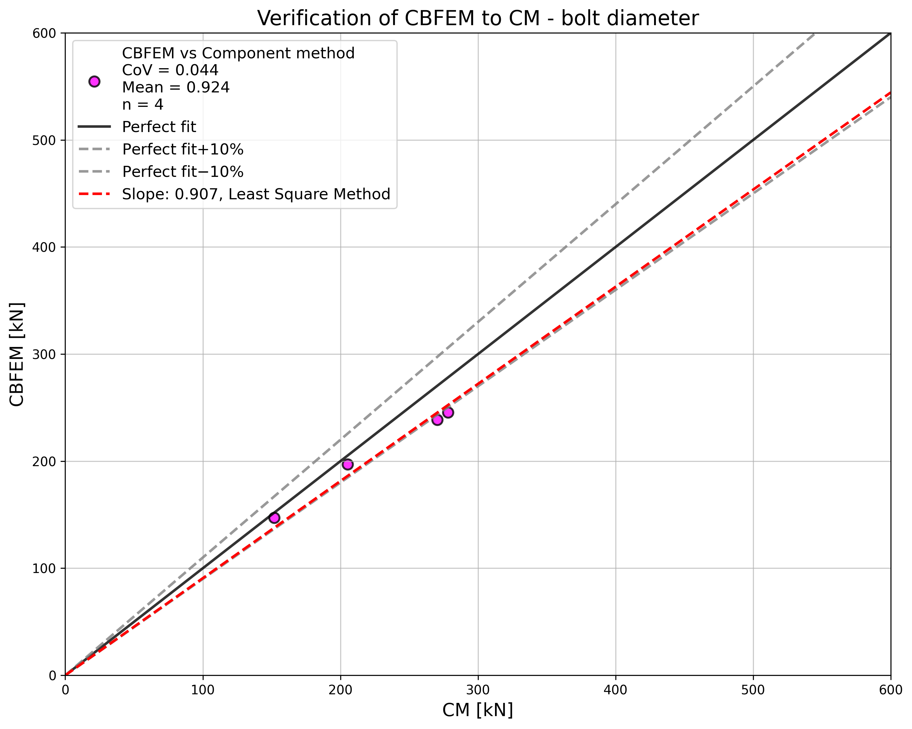
El estudio de sensibilidad del espesor del ala muestra una resistencia mayor según el CBFEM en comparación con el CM para muestras con espesores de ala de hasta 20 mm. El RM proporciona una resistencia aún mayor para estas muestras; véase Fig. 5.1.5. La mayor resistencia de ambos modelos numéricos se explica por la omisión del efecto de membrana en el CM. En el caso del diámetro del tornillo y el material del tornillo (véase Fig. 5.1.6 y Fig. 5.1.7, respectivamente), los resultados del CBFEM coinciden con los del CM. Debido a la buena concordancia entre ambos métodos, no se requieren los resultados del RM.
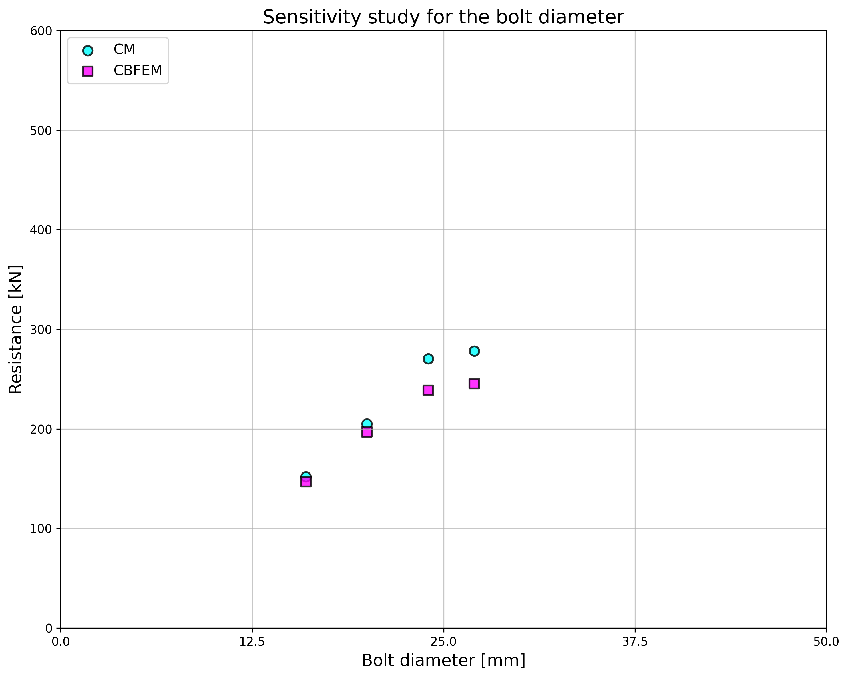
\[ \textsf{\textit{\footnotesize{Fig. 5.1.6 Sensitivity study of the bolt diameter}}}\]
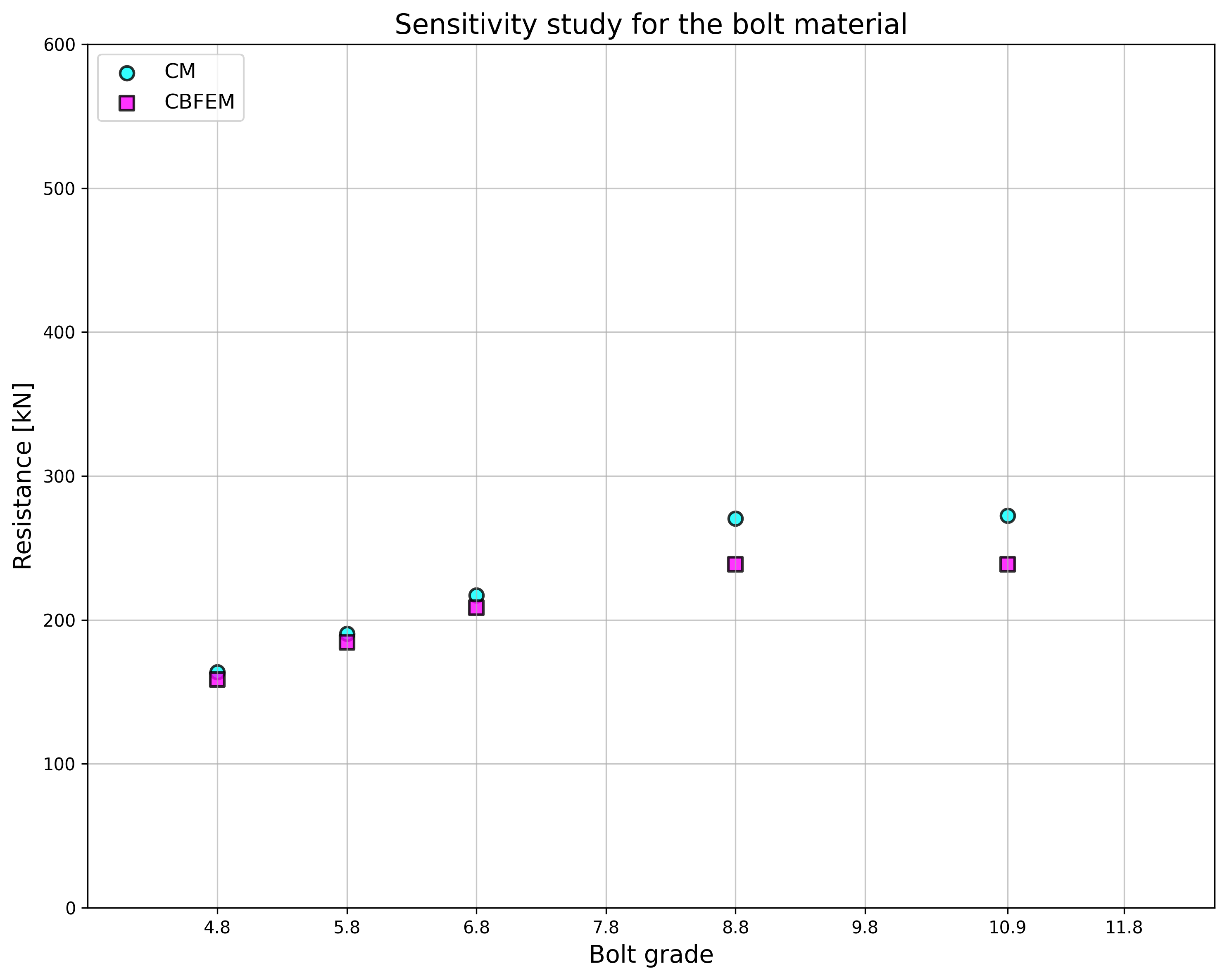
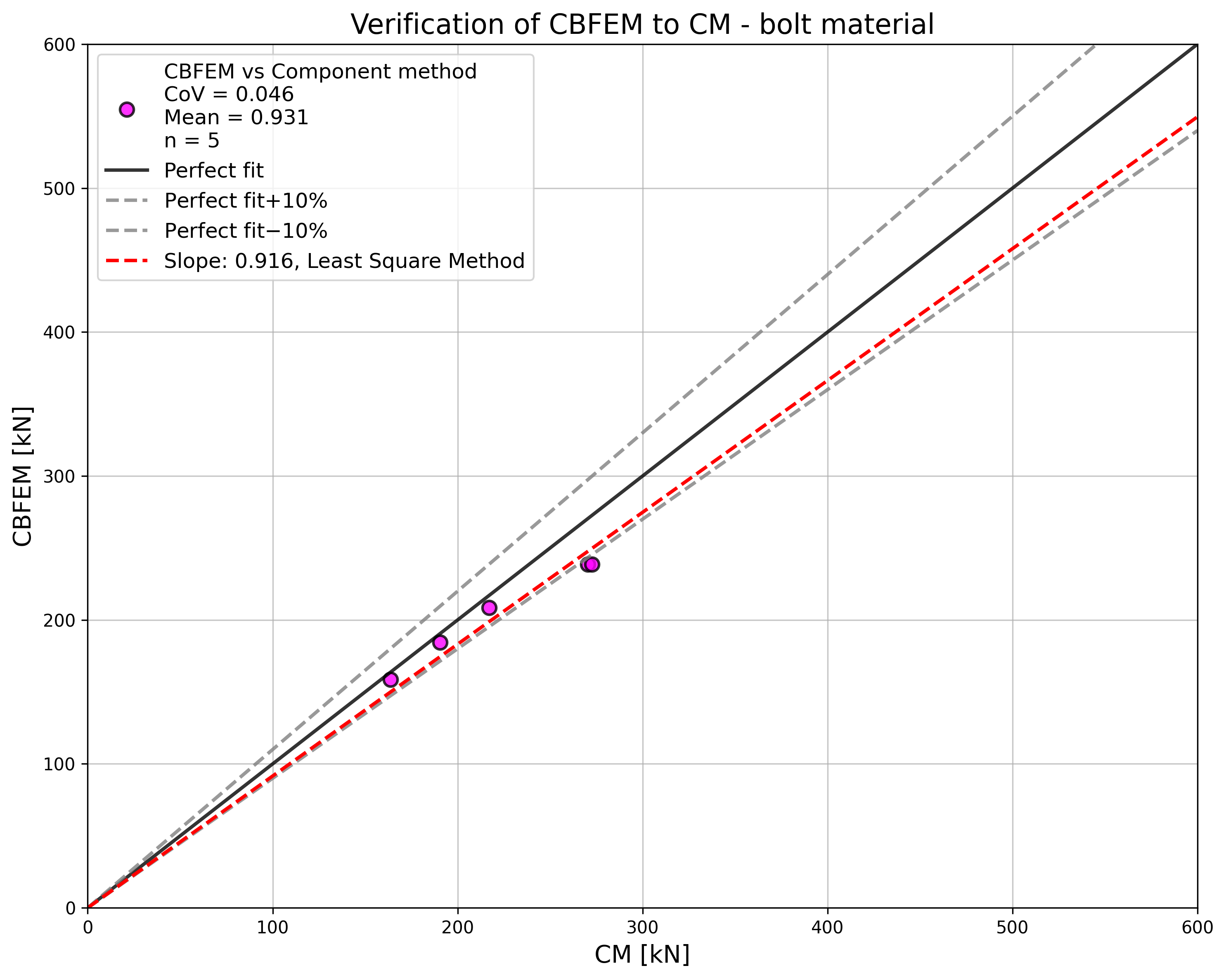
\[ \textsf{\textit{\footnotesize{Fig. 5.1.7 Sensitivity study of the bolt material}}}\]
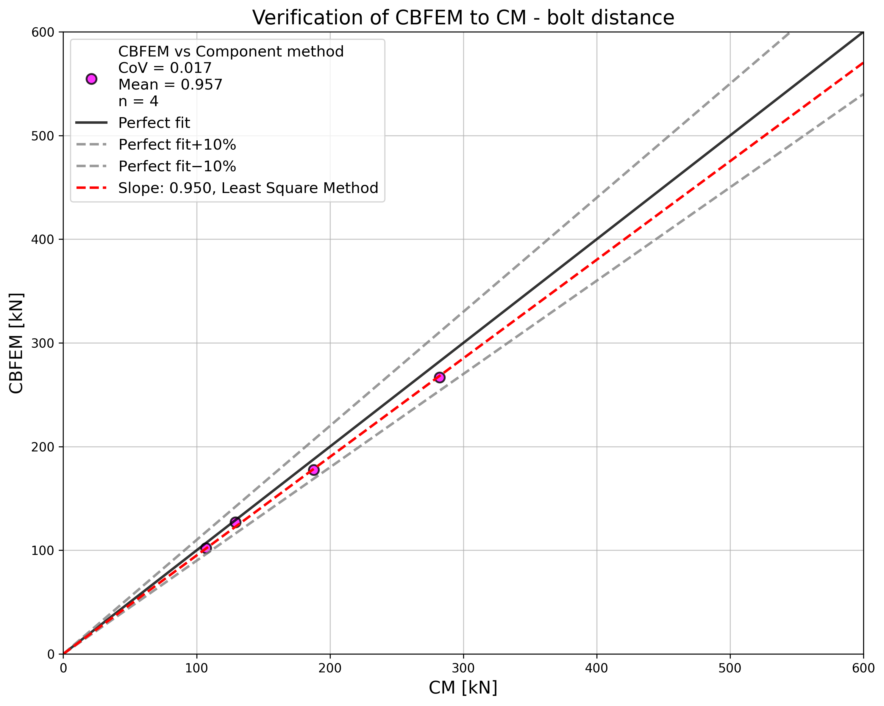
En el caso de las distancias entre tornillos, los resultados del CBFEM y del CM muestran en general una buena concordancia; véase Fig. 5.1.8. Con el aumento de la separación entre tornillos, el CBFEM proporciona una resistencia ligeramente mayor en comparación con el CM. Por esa razón, también se muestran los resultados del RM. El RM proporciona la mayor resistencia en todos los casos.
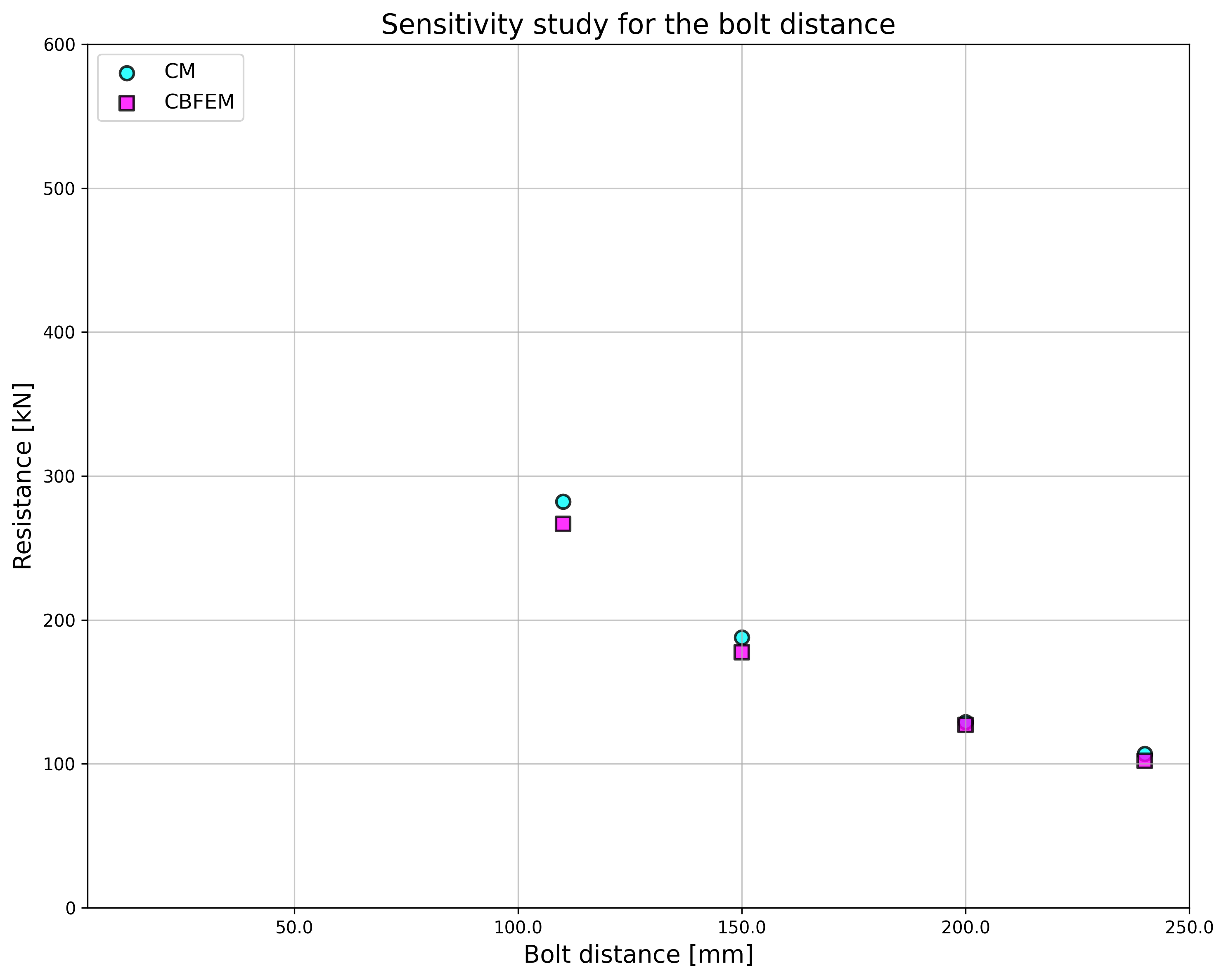
\[ \textsf{\textit{\footnotesize{Fig. 5.1.8 Sensitivity study of the bolt distance}}}\]
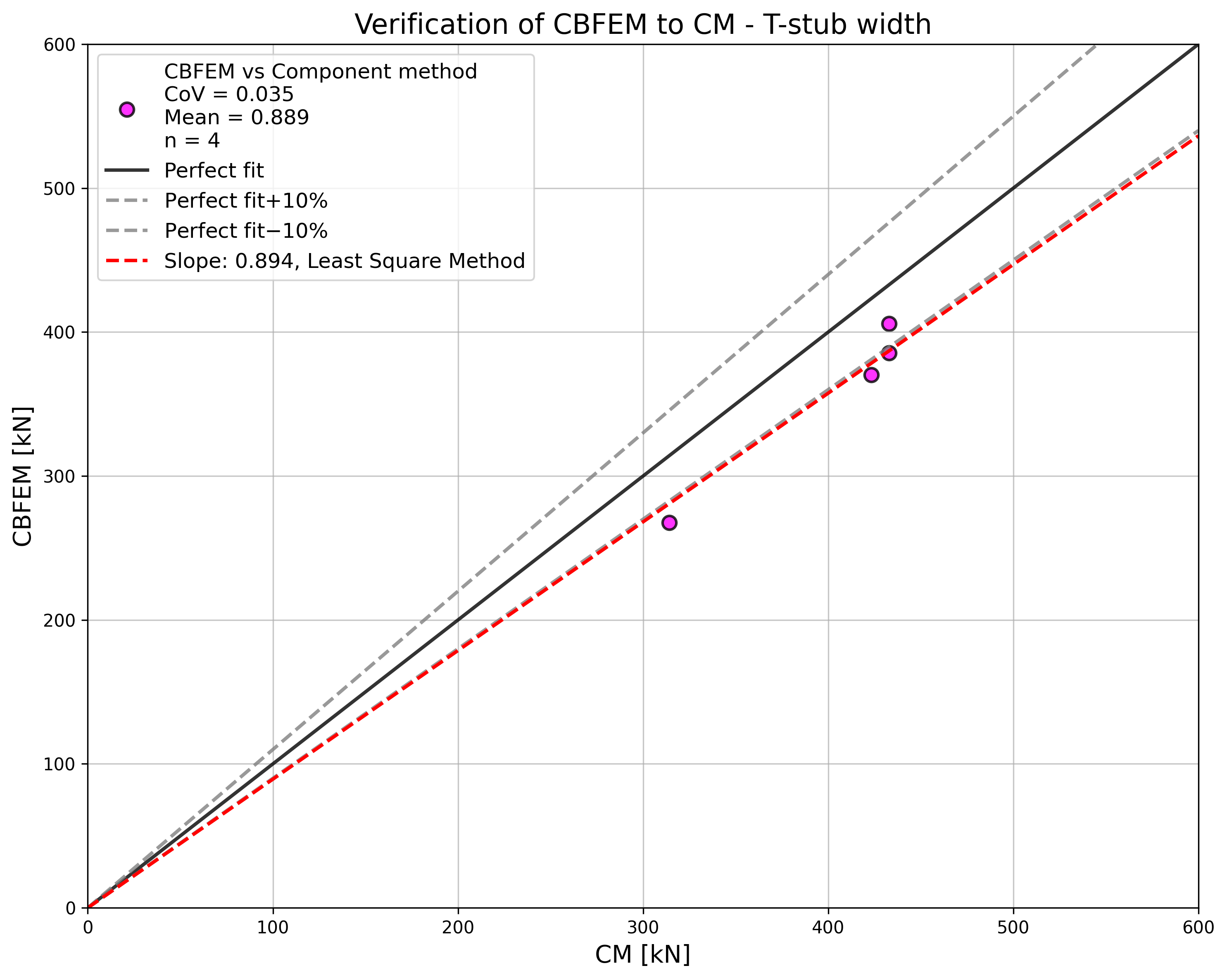
En el estudio de la anchura del perfil en T, el CBFEM muestra una resistencia mayor en comparación con el CM al aumentar la anchura. Se prepararon los resultados del RM, que nuevamente proporcionan la mayor resistencia en todos los casos; véase Fig. 5.1.9.
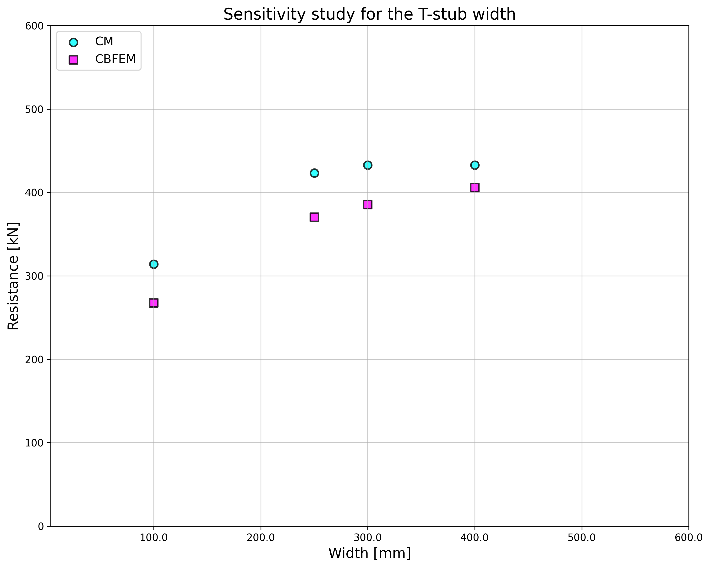
\[ \textsf{\textit{\footnotesize{Fig. 5.1.9 Sensitivity study of T-stub width}}}\]
Para mostrar la predicción del modelo CBFEM, los resultados de los estudios se resumieron en un gráfico que compara las resistencias obtenidas por CBFEM y CM; véase Fig. 5.1.10. Los resultados muestran que la diferencia entre los dos métodos de cálculo es en su mayoría de hasta el 10 %. En los casos con CBFEM/CM > 1,1, la precisión del CBFEM fue verificada mediante los resultados del RM, que proporciona la mayor resistencia en todos los casos seleccionados.
\[ \textsf{\textit{\footnotesize{Fig. 5.1.10 Summary of verification of CBFEM to CM}}}\]
Ejemplo de referencia
Datos de entrada
Perfil en T, véase Fig. 5.1.11
- Acero S235
- Espesor del ala tf = 20 mm
- Espesor del alma tw = 20 mm
- Anchura del ala bf = 300 mm
- Longitud b = 100 mm
- Soldadura en ángulo doble aw = 10 mm
Tornillos
- 2 × M24 8.8
- Distancia entre tornillos w = 165 mm
Configuración del código – Modelo y malla
- Número de elementos en el elemento o ala más grande 16
Resultados
- Resistencia de cálculo a tracción FT,Rd = 164 kN
- Modo de colapso – plastificación total del ala con deformación máxima del 5 %
- Utilización de los tornillos 86,4 %
- Utilización de las soldaduras 45,7 %

\[ \textsf{\textit{\footnotesize{Fig. 5.1.11 Benchmark example for the T-stub}}}\]
Referencias
EN 1993-1-5, Eurocode 3, Diseño de estructuras de acero – Parte 1-5: Elementos estructurales en chapa, CEN, Bruselas, 2005.
EN 1993-1-8, Eurocode 3, Diseño de estructuras de acero – Parte 1-8: Diseño de uniones, CEN, Bruselas, 2005.
Beg D., Zupančič E., Vayas I. On the rotation capacity of moment connections, Journal of Constructional Steel Research, 60 (3–5), 2004, 601–620.
Gödrich L., Wald F., Sokol Z. To Advanced modelling of end plate joints, Connection and Joints in Steel and Composite Structures, Rzeszow, 2013.
Gödrich L., Wald F., Kabeláč J., Kuříková M. Design finite element model of a bolted T-stub connection component, Journal of Constructional Steel Research. 2019, (157), 198-206.
Wu Z., Zhang S., Jiang S. Simulation of tensile bolts in finite element modelling of semi-rigid beam-to-column connections, International Journal of Steel Structures 12 (3), 2012, 339-350.