Normové posouzení součástí ocelového přípoje (HKG)
Normové posouzení plechů podle Hong Kong Code
Výsledné ekvivalentní napětí (HMH, von Mises) a plastické přetvoření jsou vypočítány na pleších. Když je dosaženo návrhové meze kluzu, \(p_y\) (Cl. 3.1.2), na bilineárním materiálovém diagramu, provede se kontrola ekvivalentního plastického přetvoření. Limitní hodnota 5 % je navržena v Eurokódu (EN 1993-1-5 App. C, Par. C8, Note 1). Tuto hodnotu lze upravit v nastavení normy, přičemž ověřovací studie byly provedeny pro tuto doporučenou hodnotu.
Prvek plechu je rozdělen do pěti vrstev a v každé z nich je zkoumáno elastické/plastické chování. Program zobrazuje nejhorší výsledek ze všech vrstev.
Napětí může být mírně vyšší než návrhová mez kluzu. Důvodem je mírný sklon plastické větve diagramu napětí-přetvoření, který je použit v analýze ke zlepšení stability výpočtu.
\[ p_y = \min \left \{ \frac{Y_s}{\gamma_{m1}}, \frac{U_s}{\gamma_{m2}} \right \} \]
kde:
- \(p_y\) – návrhová mez kluzu
- \(Y_s\) – charakteristická mez kluzu
- \(U_s\) – minimální pevnost v tahu
- \(\gamma_{m1}\) – součinitel materiálu (Table 4.1); výchozí hodnota \(\gamma_{m1} = 1\) upravitelná v nastavení normy
- \(\gamma_{m2}\) – součinitel materiálu (Table 4.1); výchozí hodnota \(\gamma_{m2} = 1.2\) upravitelná v nastavení normy
Normové posouzení svarů podle Hong Kong Code
Tupé svary
Předpokládají se tupé svary s plným průvarem a jejich únosnost se považuje za rovnocennou základnímu materiálu – čl. 9.2.5.2.1.
Koutové svary
Koutové svary jsou navrženy zjednodušenou metodou podle čl. 9.2.5.1.6.
\[ f_w \le p_w \]
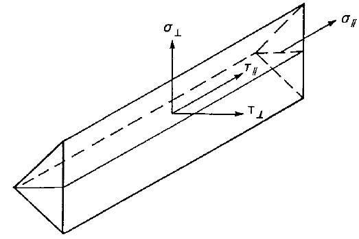
- \(f_w = \sqrt{\sigma_\perp ^2 + \tau_\perp ^2 + \tau_\parallel ^2}\) – vektorový součet napětí v krčku svaru ve všech směrech
- \(p_w\) – návrhová pevnost koutového svaru stanovená podle tabulek 9.2a a 9.2b; pro případy, na které se tabulky 9.2a a 9.2b nevztahují:
- \(p_w = \min \{0.5 U_e, 0.55 U_s\}\) – pro elektrody EN použité s ocelí EN
- \(p_w = 0.38 \min \{U_e, U_s\}\) – pro ostatní případy
- \(U_e\) – minimální mez pevnosti elektrody v tahu
- \(U_s\) – minimální mez pevnosti v tahu
Účinná délka koutového svaru je snížena o \(2\cdot s\) podle čl. 9.2.5.1.3, kde \(s\) je délka odvěsny koutového svaru uvažovaná jako \(a\cdot \sqrt{2}\).
| Elektroda | |||
| Třída oceli | 35 | 42 | 50 |
| S 275 | 220 | 220 | 220 |
| S 355 | 220 | 250 | 250 |
| S 460 | 220 | 250 | 280 |
| Třída oceli | Elektroda | Návrhová pevnost |
| Q235 | E43 | 160 |
| Q345 | E50 | 200 |
| Q390, Q420 | E55 | 220 |
Tabulky 9.2a a 9.2b: Návrhové pevnosti \(p_w\) [MPa]
| Svařovací elektroda | Minimální mez pevnosti v tahu \(U_e\) [MPa] |
| 35 | 440 |
| 42 | 500 |
| 50 | 560 |
| E43 | 421.1 |
| E50 | 526.3 |
| E55 | 578.9 |
Výchozí minimální mez pevnosti elektrody v tahu \(U_e\) [MPa]
Diagramy svarů zobrazují napětí podle následujícího vzorce:
\[ \sigma = \sqrt{\sigma_{\perp}^2 + \tau_{\perp}^2 + 3 \tau_{\parallel}^2 } \]
Normové posouzení šroubů podle Hong Kong Code
Šrouby v tahu
Únosnost šroubu v tahu je posouzena podle Cl. 9.3.7.1 jako:
\[ P_t = A_s \cdot p_t \]
kde:
- \(A_s\) – plocha průřezu v tahu
- \(p_t\) – pevnost v tahu získaná z Tabulky 9.8
Páčící síly jsou zohledněny analýzou metodou konečných prvků.
Šrouby ve smyku
Únosnost šroubu ve smyku je převzata podle Cl. 9.3.6.1.1 jako:
\[ P_s = p_s \cdot A_s \]
kde:
- \(p_s\) – návrhová pevnost ve smyku získaná z Tabulky 9.5
- \(A_s\) – efektivní plocha ve smyku; \(A_s = A_t\) pokud závity jsou přerušeny smykovou rovinou, jinak se \(A_s\) uvažuje jako průřezová plocha dříku
- \(A_t\) – plocha průřezu v tahu
Podle Cl. 9.3.6.1.6, pokud šroub prochází podložkou o tloušťce \(t_{pa}\) větší než jedna třetina jmenovitého průměru \(d\), jeho únosnost ve smyku \(P_s\) musí být snížena vynásobením redukčním součinitelem \(\beta_p\) získaným z:
\[ \beta_p = \frac{9d}{8d+3t_{pa}} \le 1 \]
Šrouby v kombinaci tahu a smyku
Kombinace tahu a smyku je posouzena podle Cl. 9.3.8.1 jako:
\[ \frac{F_s}{P_s} + \frac{F_{tot}}{P_t} \le 1.4 \]
kde:
- \(F_s\) – smyková síla ve šroubu
- \(P_s\) – únosnost šroubu ve smyku
- \(F_{tot}\) – celková tahová síla ve šroubu včetně páčící síly
- \(P_t\) – tahová únosnost šroubu
Šrouby v otlačení
Únosnost šroubu v otlačení je převzata podle Cl. 9.3.6.1.2 jako:
\[ P_{bb} = d \cdot t_p \cdot p_{bb} \]
kde:
- \(d\) – jmenovitý průměr šroubu
- \(t_p\) – tloušťka připojeného plechu
- \(p_{bb}\) – pevnost šroubu v otlačení získaná z Tabulky 9.6
Každý plech je posouzen samostatně a je zobrazen nejhorší výsledek.
Únosnost připojených částí v otlačení je převzata podle Cl. 9.3.6.1.3 jako minimum z následujících:
\[ P_{bs} = k_{bs} \cdot d \cdot t_p \cdot p_{bs} \]
\[ P_{bs} = 0.5 \cdot k_{bs} \cdot e \cdot t_p \cdot p_{bs} \]
\[ P_{bs} = 1.5 \cdot l_c \cdot t_p \cdot U_s \le 2.0 \cdot d \cdot t_p \cdot U_b \]
kde:
- \(k_{bs}\) – součinitel otvoru uvažovaný jako
- pro standardní otvory \(k_{bs} = 1.0\)
- pro zvětšené a krátké drážkové otvory \(k_{bs} = 0.7\)
- pro dlouhé drážkové otvory \(k_{bs} = 0.5\)
- \(d\) – jmenovitý průměr šroubu
- \(t_p\) – tloušťka připojeného plechu
- \(p_{bs}\) – pevnost připojených částí v otlačení
- pro ocel třídy S275, \(p_{bs} = 460\) MPa
- pro ocel třídy S355, \(p_{bs} = 550\) MPa
- pro ocel třídy S460, \(p_{bs} = 670\) MPa
- pro ocel jiných tříd, \(p_{bs} = 0.67 (U_s+Y_s)\)
- \(e\) – vzdálenost okraje ve směru smykové síly měřená od osy šroubu
- \(l_c\) – čistá vzdálenost mezi otlačovaným okrajem otvorů a blízkým okrajem sousedního otvoru ve stejném směru přenosu zatížení
- \(U_s\) – minimální pevnost připojeného plechu v tahu
- \(Y_s\) – charakteristická mez kluzu připojeného plechu
- \(U_b\) – stanovená minimální pevnost šroubu v tahu
Normové posouzení šroubů a předepnutých šroubů podle Hong Kong Code
Únosnost ve smyku
Únosnost předepnutých šroubů ve smyku je stanovena podle Cl. 9.3.6.2 jako:
\[ P_{SL} = 0.9 \cdot K_s \cdot \mu \cdot P_0 \]
kde:
- \(K_s\) – součinitel otvoru, uvažovaný jako
- pro standardní otvory \(K_s = 1.0\)
- pro zvětšené otvory \(K_s = 0.85\)
- pro drážkové otvory \(K_s = 0.7\)
- \(\mu\) – součinitel prokluzu mezi spojenými částmi z Tabulky 9.7; editovatelný v nastavení normy
- \(P_0\) – minimální předpínací síla šroubů stanovená příslušnými mezinárodními nebo místními normami
Kombinace tahu a smyku
Kombinace tahu a smyku je posuzována podle Cl. 9.3.8.2 jako:
\[ \frac{F_s}{P_{SL}}+\frac{F_{tot}}{0.9\cdot P_0} \le 1.0 \]
kde:
- \(F_s\) – smyková síla ve šroubu
- \(P_{SL}\) – únosnost předepnutého šroubu v prokluzu
- \(F_{tot}\) – celková působící tahová síla ve šroubu včetně páčící síly
- \(P_0\) – stanovená minimální předpínací síla předepnutého šroubu
Normové posouzení betonového bloku podle Hong Kong Code
Beton v otlačení
Beton v otlačení je posuzován podle CoP – SUoS – Cl. 9.4.1 jako:
\[ \sigma \le w \]
kde:
- \(\sigma\) – průměrné tlakové napětí na účinné ploše \(A_{eff}\), která je průnikem dvou ploch:
- \(A_{CM}\) – účinná plocha stanovená podle Cl. 9.4.1 pro čistý tlak
- \(A_{FEM}\) – plocha pod patní deskou v kontaktu s betonem stanovená metodou konečných prvků
- \(w = 0.6 f_{cu}\) – únosnost betonu v tlaku při soustředěném zatížení
- \(f_{cu}\) – minimální charakteristická pevnost betonu v tlaku
Účinná plocha \(A_{CM}\) je plocha ocelového prvku včetně výztuh přivařených k patní desce, zvětšená o přesah \(c\):
\[ c = t_p \sqrt{\frac{p_{yp}}{3w}} \]
kde:
- \(t_p\) – tloušťka patní desky
- \(p_{yp}\) – návrhová hodnota meze kluzu patní desky
Tlak pod tlačenou zónou je uvažován jako rovnoměrný.
Přenos smyku
Předpokládá se, že smykové účinky v patní desce jsou přenášeny ze sloupu do betonového základu:
- Třením mezi patní deskou a betonem/zálivkou
- Smykovou zarážkou
- Kotevními šrouby
Kotvy
Tahové síly v kotvách zahrnují páčící síly a jsou stanoveny metodou konečných prvků.
Kotvy nejsou v softwaru posuzovány.
Detailování šroubů a svarů podle hongkongské normy
Šrouby
Minimální rozteč šroubů je podle Cl. 9.3.1.1: Vzdálenost středů šroubů musí být větší než \(2.5 \cdot d\), kde \(d\) je jmenovitý průměr šroubu.
Minimální okrajová vzdálenost měřená od osy šroubu je podle Tabulky 9.3:
| Velikost šroubu | Minimální okrajová vzdálenost [mm] |
| M12 | 18 |
| M16 | 22 |
| M18 | 24 |
| M20 | 26 |
| M22 | 28 |
| M24 a větší | \(1.25 \cdot d\) |
Svary
Minimální délka odvěsny koutového svaru je posuzována podle Tabulky 9.1.
| Tloušťka nejsilnější části [mm] | Minimální délka odvěsny [mm] | Minimální tloušťka hrdla [mm] |
| \(t \le 6\) | 3 | 2.121 |
| \(6 < t \le 13\) | 5 | 3.536 |
| \(13 < t \le 19\) | 6 | 4.243 |
| \(19 > t \) | 8 | 5.657 |
Kapacitní návrh podle Hong Kong Code
Kapacitní návrh není podle hongkongských norem vyžadován.
Klasifikace podle tuhosti pro Hong Kong Code
Styčníky jsou klasifikovány podle tuhosti styčníku na:
- Tuhý – styčníky s nevýznamnou změnou původních úhlů mezi prvky,
- Polotuhý – styčníky, u nichž se předpokládá schopnost zajistit spolehlivý a známý stupeň ohybového ztužení,
- Kloubový – styčníky, které nevyvíjejí ohybové momenty.
Styčníky jsou klasifikovány podle EN 1993-1-8 – Cl. 5.2.2.
- Tuhý – \( \frac{S_{j,ini} L_b}{E I_b} \ge k_b \)
- Polotuhý – \( 0.5 < \frac{S_{j,ini} L_b}{E I_b} < k_b \)
- Kloubový – \( \frac{S_{j,ini} L_b}{E I_b} \le 0.5 \)
kde:
- Sj,ini – počáteční tuhost styčníku; tuhost styčníku se předpokládá lineární až do 2/3 hodnoty Mj,Rd
- Lb – teoretická délka posuzovaného prvku; nastavuje se ve vlastnostech prvku
- E – modul pružnosti (Youngův modul)
- Ib – moment setrvačnosti posuzovaného prvku
- kb = 8 pro rámy, kde ztužující soustava snižuje vodorovné posunutí o nejméně 80 %; kb = 25 pro ostatní rámy, za předpokladu, že v každém podlaží Kb/Kc ≥ 0,1. Hodnota kb = 25 se používá, pokud uživatel nenastaví „ztužená soustava" v nastavení normy.
- Mj,Rd – návrhová hodnota momentové únosnosti styčníku
- Kb = Ib / Lb
- Kc = Ic / Lc