
Unlock new possibilities with advanced anchoring
Whether it’s limited space for anchoring, an unconventional architectural layout, anchoring close to the edge, the need to fasten steel to irregular concrete shapes, or the demand from the construction site to design cast-in plates, these special cases demand more than just typical solutions. That’s exactly where the real design challenge begins.
How do structural engineers actually deal with these situations?
It starts with assumptions and a lot of manual work and calculations. Hours are spent iterating designs and code-checking. More than often analysed designs lead to unnecessarily oversized footings and plates due to concrete breakouts:
- Concrete edge failure
- Concrete cone failure
- Combination of failures
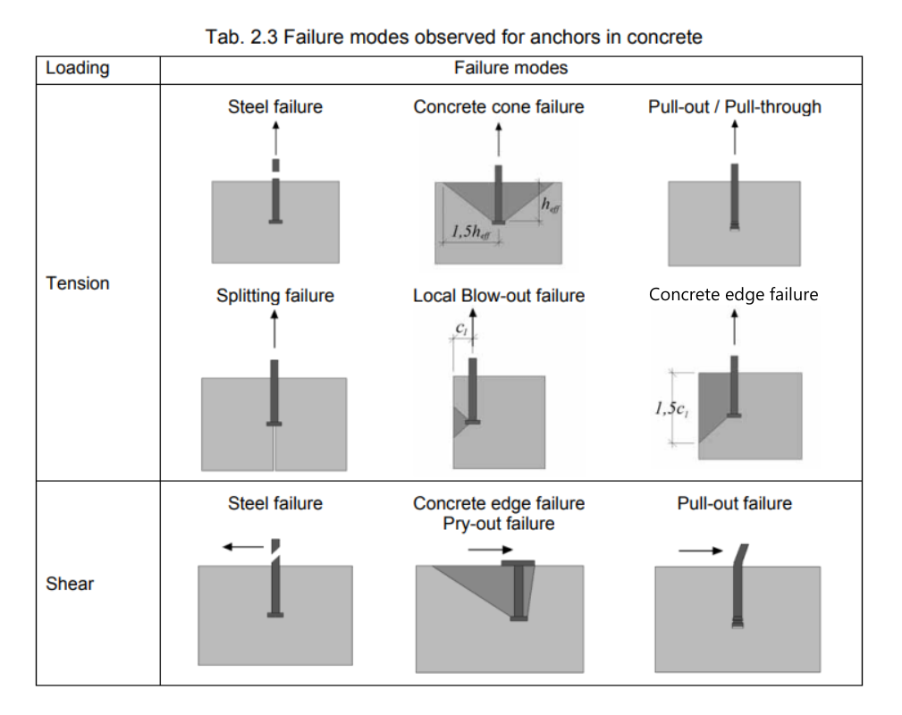
Take anchoring near the edge, for example. Without reinforcement, it's almost impossible to pass a code-check for concrete edge or cone failure. When anchors are close to each other, you’re suddenly dealing with interacting cones—something most codes advise avoiding altogether. But what do you do when your layout simply doesn't allow for the recommended spacing?
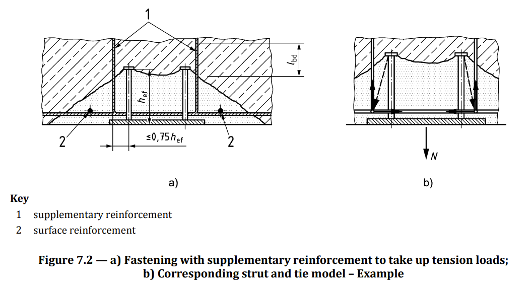
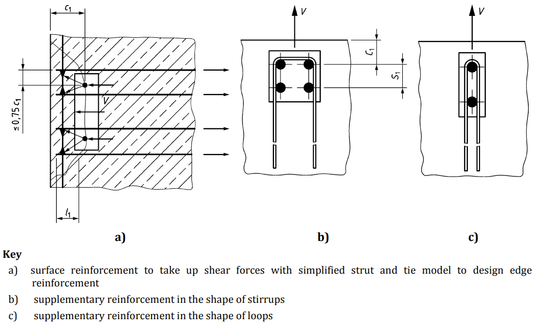
Supplementary reinforcement needs to be considered. Eurocode 1992-4 - Design of concrete structures - Part 4: Design of fastenings for use in concrete recommends establishing an appropriate strut and tie model.
But what if an atypical shape of concrete block throws a spanner in the works?
Tackling anchoring challenges of non-standard concrete block geometries
Especially when dealing with irregular geometries or unique layouts that go beyond standard textbook cases, the process is not only time-consuming but also leaves too much room for uncertainty. In such cases, the general shapes can be unpredictable, making it crucial to carefully consider edge distances on all sides. Embedment depth may vary due to differences in block thickness or anchor positioning, and the anchors themselves may not be in the same plane.
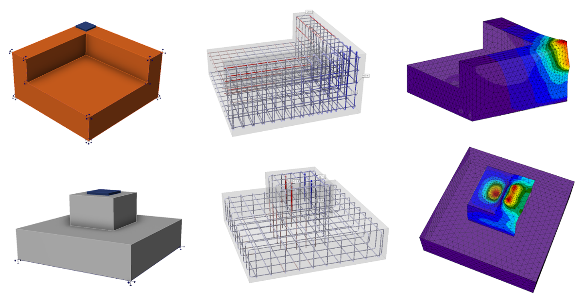
In the latest release of IDEA StatiCa, we’ve added powerful new capabilities to help you design and code-check anchoring in the real-world conditions that do not follow the textbook.
You can now design and code-check almost any shape of concrete block for anchoring. Whether it’s a pedestal, non-rectangular anchor blocks, extensions of strip foundation, any shape of a wall, or a custom geometry required by architects.
Reinforcement-aware design of cast-in plates
In the construction industry, it's common to encounter supporting structures that incorporate both steel and concrete elements. The concrete components often play a key role in providing lateral stability to the steel framework. These elements are typically linked through the use of cast-in plates. Cast-in plates offer reliable anchorage, moreover, they can be fabricated to minimize drilling on construction site. Plates sit flush with the concrete surface, allowing clean and level connections. Cast-in plates are especially favored in applications such as façade support systems, steel frame connections in hybrid concrete-steel buildings, elevator guide rail supports, anchoring mechanical equipment, bridge bearings, and precast concrete panel connections.
But while their applications are broad, the design can become significantly more complex. The axial forces are resisted by reinforcement in the concrete, which is welded to the steel plate to transfer the load through bond with the concrete. Shear studs, anchors or shear lug resist the shear forces.
The design resistance of the embedded elements is highly dependent on the position of the concrete reinforcement, especially if the cast-in plate is positioned close to the edge (supporting façade systems).
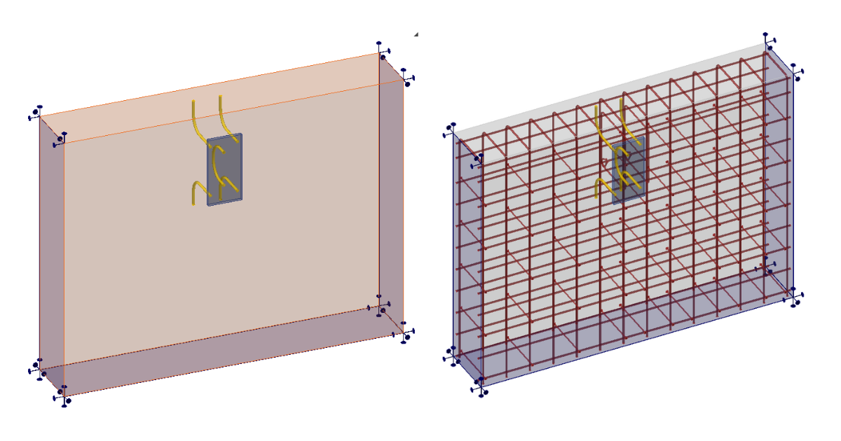
Detail (with CSFM 3D) automatically takes into account the reinforcement near the cast-in plate, which can significantly increase the loading capacity. This solution allows you to perform designs without oversimplifications and provides checks based on the Ultimate Limit State (ULS).
Taking anchor design to the next level
IDEA StatiCa provides engineers with a comprehensive solution for the design and code-check of anchoring. Engineers are no longer constrained by simplified, conservative textbook examples matching the design codes, leading to overdesigning baseplates and anchors. By taking into consideration the reinforcement in the concrete block, engineers can achieve safe, accurate, and cost-effective designs.
It’s time to move beyond the textbook and design anchorage systems that truly reflect the complexity and demands of modern structural applications.
Vyzkoušejte si IDEA StatiCa ještě dnes
Kompletní posouzení kotev a betonových bloků pomocí IDEA StatiCa
IDEA StatiCa Detail – Structural design of concrete 3D discontinuities
