Connections Workshop – case study 1
Building with Steel, in cooperation with TC10, organized a connections workshop for structural engineers at Kampstaal in Emmeloord.
During this hands-on workshop, 36 engineers, divided into six teams, and set to work on two challenging design issues. Each team was tasked with designing a steel connection with attention to both structural performance and practicability.
The teams consisted of structural engineers from engineering firms and steel fabricators, and each was guided by an experienced connection designer. After the groups presented their designs, we from IDEA StatiCa had the opportunity to model the connections with the Connection application. That way, we were able to analyze the results immediately and discuss them together.
We explain the designs and results in more detail below. In this first article, we will discuss Case 1, in which the engineers were given the following task.
Case study one
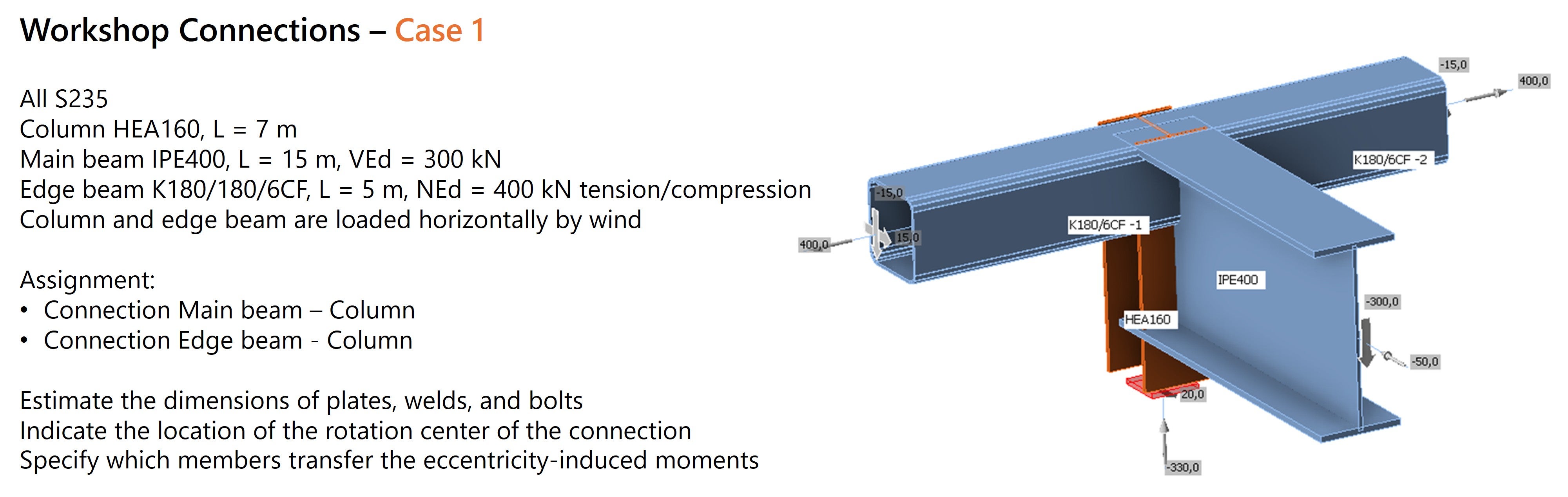
In the first case study, we looked at a node in which four bars come together. Due to the nature of the internal forces and profiles, this did not prove to be an easy design issue, and this was evident from the diversity of solutions proposed: the six teams each came up with a unique approach. This is exactly what makes this profession so fascinating; there is never one right solution.
The biggest challenge arose with the connection of the edge bars. Two rectangular tubes (180/180/6) had to be connected to a column (HEA160) or edge beam (IPE400). Combined with the imposed loads, this created a difficult design situation.
Below is an overview of the connections, sketches and models worked out in IDEA StatiCa. We then discuss each connection and highlight key insights from the discussions and results.
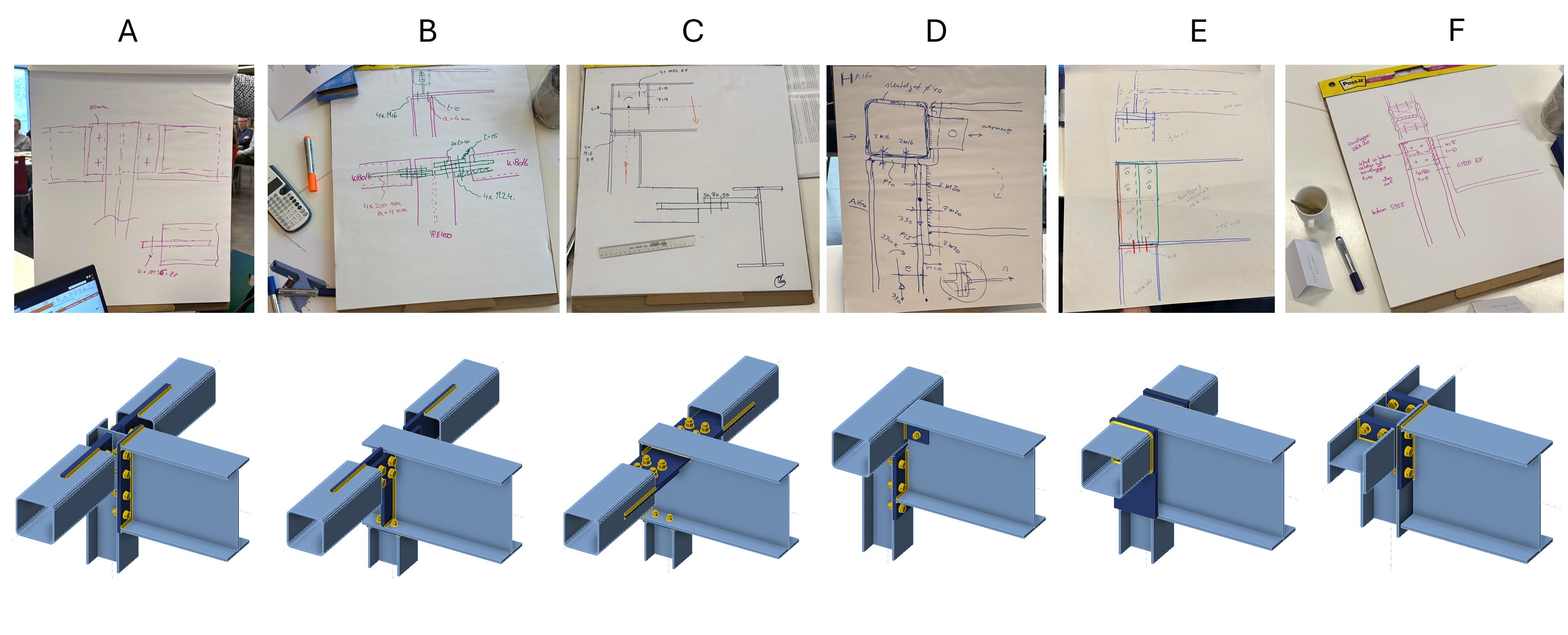
Group A
Group A chose to continue the column and connect the roof beam (IPE400) with a head plate. The challenge was mainly in connecting the edge bars to the HEA160 column. For this, a lip plate connection with two M36 bolts was proposed. When modeling in IDEA StatiCa, however, it quickly became apparent that there was insufficient space for this bolt size. As the experts at TC10 emphasized, it is essential to draw to scale to understand the manufacturability of a connection.
The group deliberately chose to extend the sketch plate through a slot in the column body to better transfer forces and reduce stresses in the body.
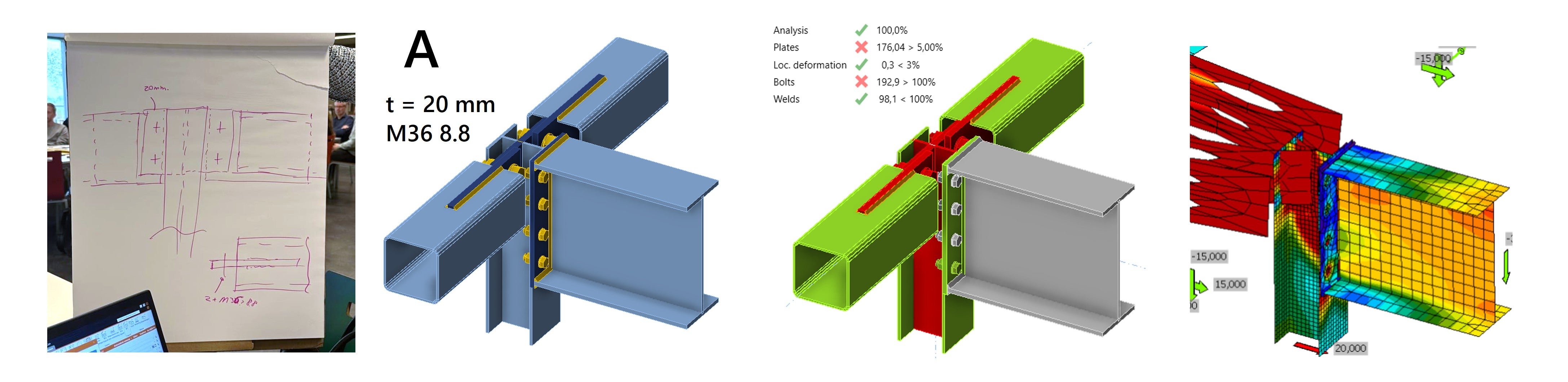
When calculating the connection in IDEA StatiCa, large plastic strains arise in the connection of the tubes. Due to the high axial compressive force of 400 kN in the edge bars and an eccentricity in the gusset plate, a bending moment occurs in the connection. In IDEA StatiCa, this quickly becomes visible through the deformations that occur.
By increasing the plate thicknesses, the connection can meet the requirements. With a continuous 35 mm sketch plate and 2x M33 8.8 bolts, sufficient strength and rigidity is achieved.
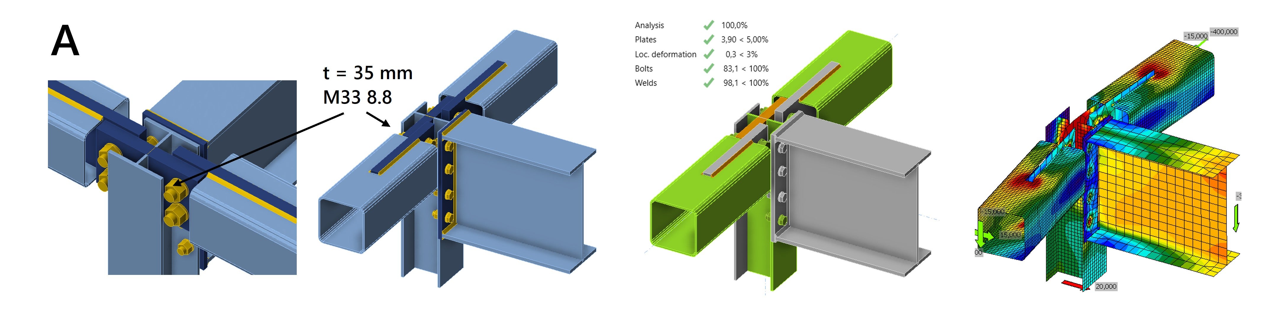
Although the solution is satisfactory, avoiding the eccentricity is worth considering and probably more structurally efficient.
Group B
Group B had a similar connection, but here the roof beam was extended. Choosing a symmetrical connection of the edge bars avoids the additional bending moment. With the prescribed plate thicknesses, we just barely fall below 5% plastic strain.
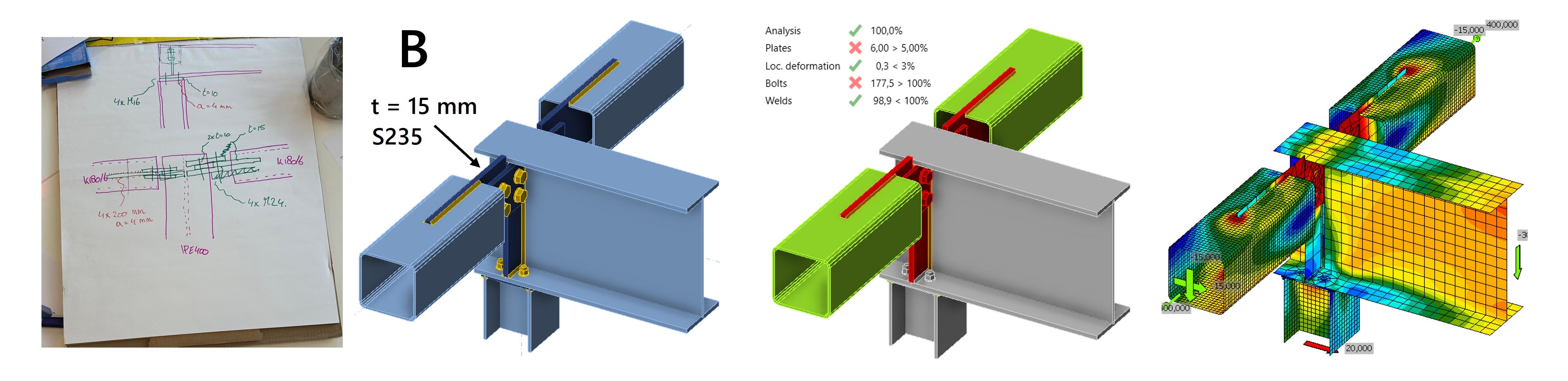
By thickening the plates, the combination of axial compression force and horizontal transverse force can be resisted and the plastic strain remains below 5%.
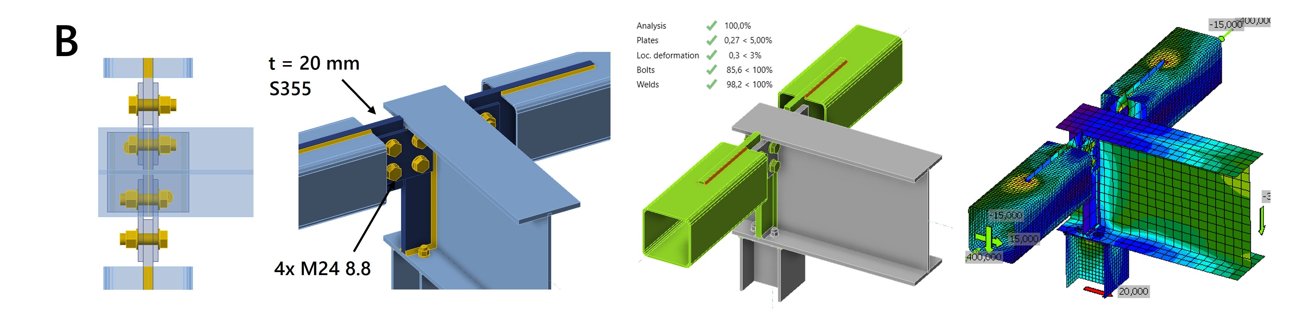
Only the bolts are still not satisfactory when using 4x M24 8.8. However, simply reinforcing the bolts does not solve the problem because the testing is limited by the thrust resistance. An alternative solution is to increase the steel grade of the connection plates to S355. With this, with minimal plate thickening and bolt size, optimum results can be achieved.
Group C
Group C has a similar connection, but unlike groups A and B, it is more suitable for horizontal loading because the sketch plate is rotated a quarter turn. We are again dealing with an eccentricity and encounter the same problems as in Group A. The use of four bolts instead of two makes the joint stiffer, but we still see high plastic strain and deformation. Welding to the stiffened end plate and increasing the plate thicknesses help make the joint stiffer, but eccentricity will always be present.
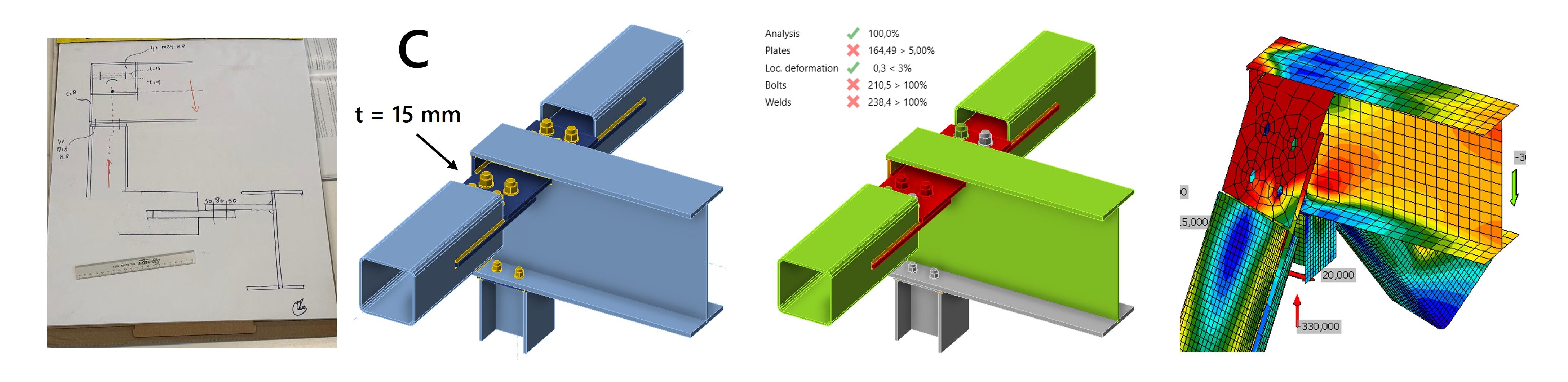
By increasing the plate thicknesses from 15 mm to 30 mm, the joint can meet the design requirements with 4x M24 8.8 bolts.
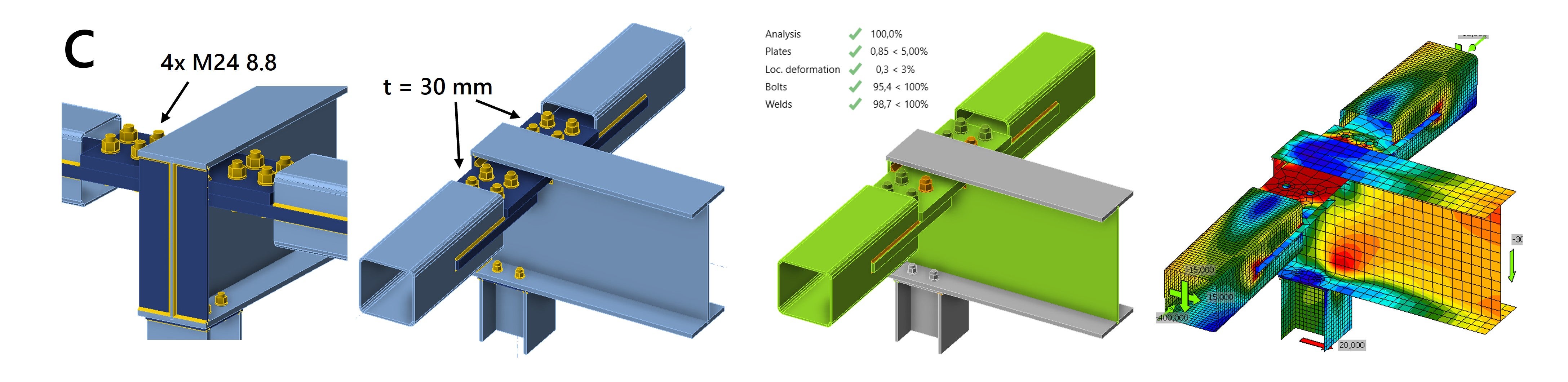
This type of joint functions most safely without eccentricities. If an eccentricity is unavoidable due to practical output, the joint will be especially suitable for transferring a transverse force in one direction, in the direction where the joint is stiffest. The combination of an eccentricity with large normal compressive force and a transverse force in the weak direction of the connection will cause the bar to bend out and risk buckling.
Buckling analysis
To properly assess this risk, it makes sense to perform an additional buckling calculation. With IDEA StatiCa, a linear buckling analysis can be performed, which shows that for too thin plate thicknesses, a buckling shape can occur that can be classified as global buckling.
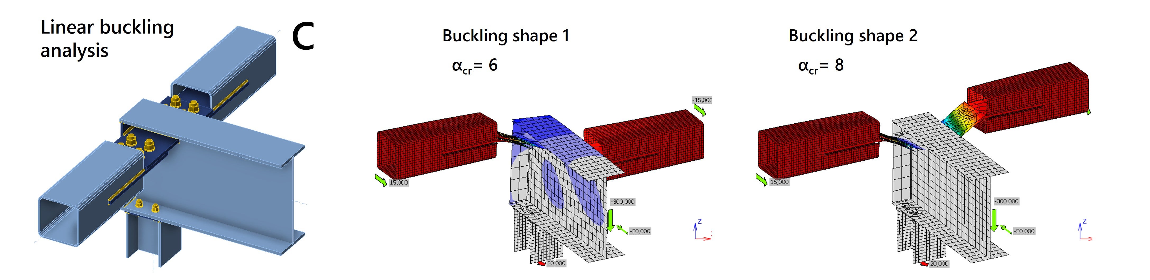
More information about this and how IDEA StatiCa performs linear buckling analysis can be found in the following article Global buckling vs. local buckling. What does it mean?
Group D
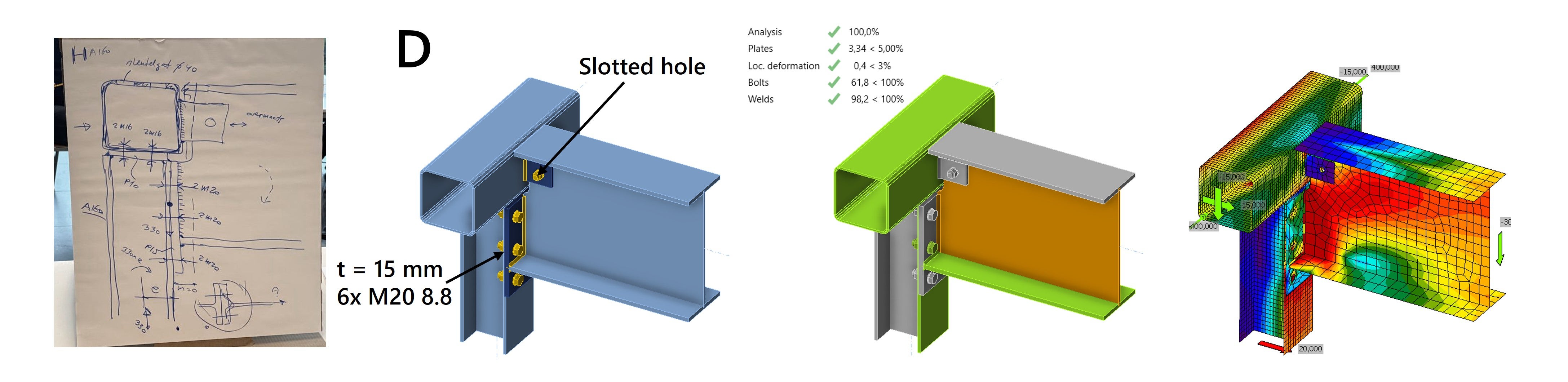
Group D takes a different approach and the problems seen in the first three groups are directly avoided by continuing the edge bar. The IPE400 is connected to the partially continuous column with a head plate and to the edge bar with a small lip plate. The results show that the connection performs constructively well and the forces are efficiently transmitted.
The group recommends a slotted hole in the lip plate to prevent too much force being transmitted through the bolt when the beam rotates. This avoids high stresses in the lip plate and box wall. This design consideration also affects the rotational stiffness of the joint.
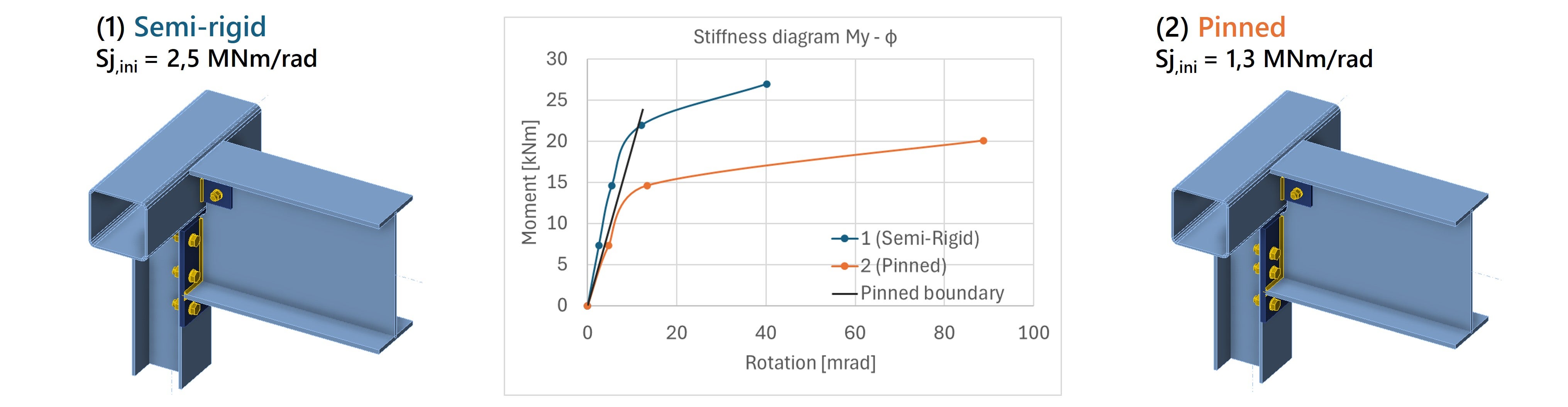
Stiffness analysis
To determine the exact stiffness of the joint, stiffness analysis can be performed with IDEA StatiCa. The moment-rotation diagram is generated and based on the Eurocode, the joint can be classified as fully rigid, flexible (semi-rigid), or pinned.
Analyzing the connection of the roof girder for Group D, IDEA StatiCa gives a rotational stiffness that is considered flexible. This stiffness can be modeled in the global structural model with a rotation spring.
However, if a hinged connection is required, the detail must be modified so that the connection is actually classified as hinged . As shown in the figure below, in situation (2) a hinge has been realized by lowering the top bolt row.
Group E
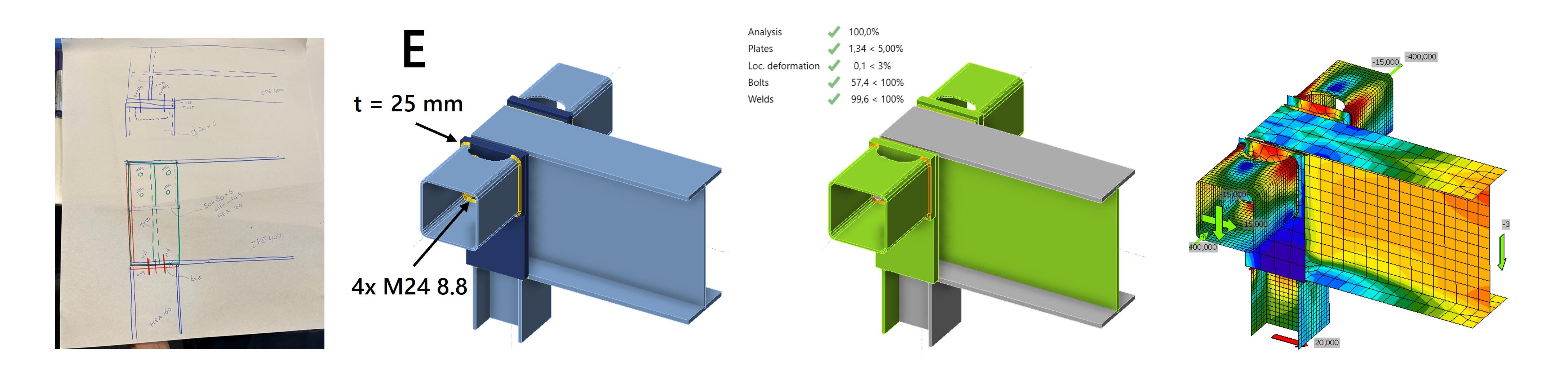
Group E extended the roof beam and placed it on top of the column. The edge rods were attached to the roof girder with end plates, ensuring that the forces are properly transmitted in the joint.
To allow for the mounting of the bolts, the group proposed a cutout in the box section. A thoughtful solution, since practicality is a major concern. The cut creates a different stress distribution in the socket, but by applying a round cutout, stress concentrations remain limited.
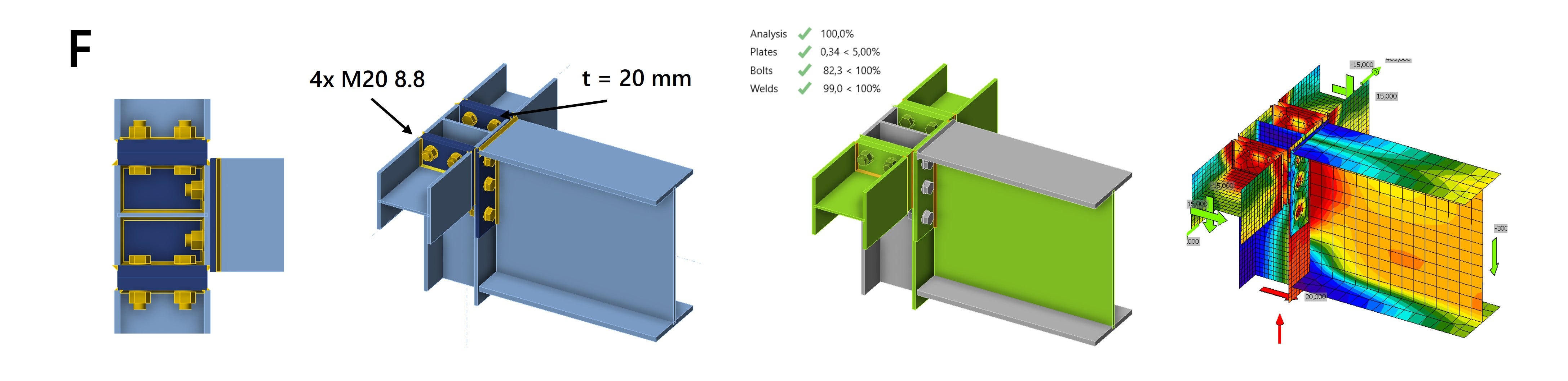
Group F
As we have seen, the connection of the edge bars creates design challenges. Group F solves these by replacing the edge bars with HEA160 sections. This makes it easier to connect the beams to the column, and provides sufficient space for mounting the bolts. The connection performs well under pressure, and the head plates efficiently channel the forces through the column.
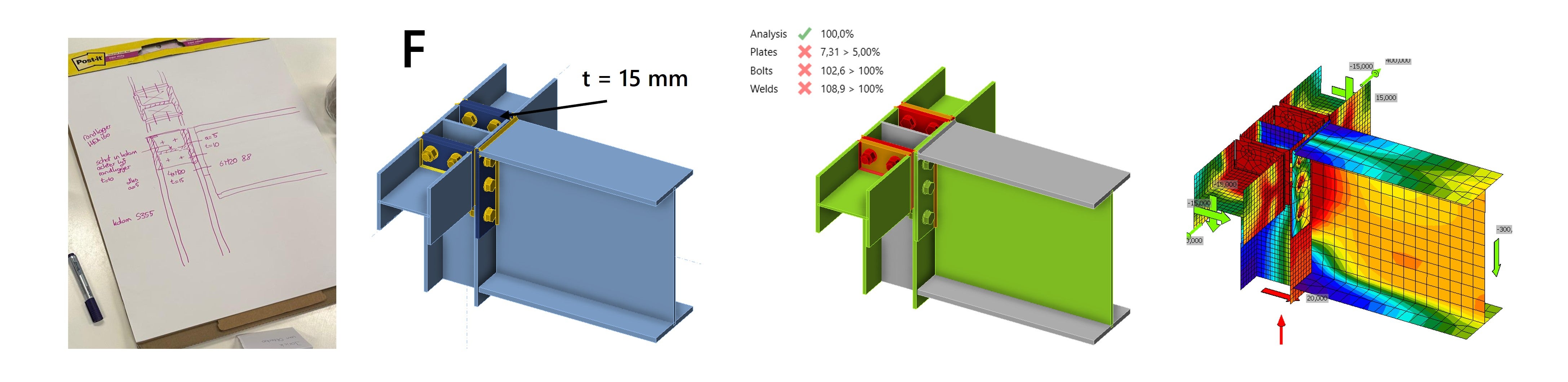
However, the edge bars can also come under a tensile load of 400 kN. In this load case, the connection is not satisfactory. By increasing the thickness of the head plates from 15 mm to 20 mm, the strength requirements are met and the connection is suitable for tensile and compressive loads.
Final word
The steel connection of case study one was designed by six groups, modeled in IDEA StatiCa and discussed with experienced structural engineers. We were able to analyze the results through the use of IDEA StatiCa, in which a number of concerns emerged. This workshop shows that many connections can be designed in an infinite number of ways and that there is never one correct solution. We experienced the importance of drawing to scale and following the path of forces in the connection. Analyzing the stiffnesses and visualizing how the joint will deform is a good thought experiment to understand how a joint will behave.
"Imagination is more important than knowledge" a man named Albert Einstein once said. And that certainly applies to steel joint design as well. Anyone who can imagine what a joint looks like, how it will be made, whether the proportions are right, how the forces will flow and how the joint will deform is already one step closer to becoming the best joint designer.
In the next article we will discuss case study two, in which engineers were asked to design a column base plate connection with wind bracing.
Vyzkoušejte si IDEA StatiCa ještě dnes