Reținere la flambaj lateral-torsional în proiectarea structurală
Descrierea modelului
Reținerea la flambaj lateral-torsional este simulată prin două rigidități adăugate oricărei plăci:
- Laterală (la forfecare) S [N] aplicată în direcția axei y a sistemului de coordonate locale al plăcii
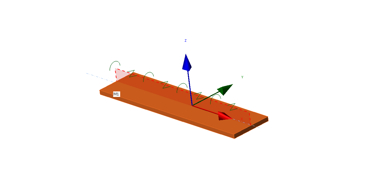
- Torsională C [Nm/m] aplicată în jurul axei x a sistemului de coordonate locale al plăcii
Utilizatorii pot selecta orice placă a unui element, lungimea reținerii, tipul (continuu sau discret cu pas prestabilit) și rigiditățile laterală și torsională.
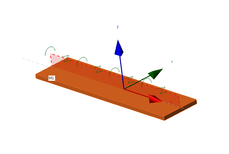
Sistemul de coordonate locale al unei plăci cu LTR aplicat
Nodurile elementelor finite sunt conectate de-a lungul lățimii plăcii prin elemente de corp rigid de tip 3 (RBE3) la un punct de pe axa longitudinală a plăcii. Rigiditatea torsională este aplicată în acest punct printr-un element special cu o singură rigiditate, rotație în jurul axei x. Acest punct este conectat și prin alte două RBE3 cu un element special între ele, cu o singură rigiditate, deplasare pe axa y.
Rigiditatea laterală este setată de utilizator ca liberă, rigidă sau cu rigiditate prestabilită. Rigiditatea rigidă este suficient de mare, setată ca de 1000 de ori rigiditatea la forfecare a plăcii. Rigiditatea \(S\) este setată pe unitatea de lungime (un metru) cu unitate de forță [N]. Rigiditatea unui element \(S_i\) are unitatea de forță împărțită la unitatea de lungime [N/m] și este:
\[ S_i = \frac{S}{s_d} \]
unde:
- \(s_d\) – distanța dintre două puncte [m]
Pentru tipul discret, pasul este setat direct de utilizator. Pentru tipul continuu, pasul este suficient de mic astfel încât comportamentul plăcii să nu fie influențat de acesta.
Similar, rigiditatea torsională este setată de utilizator ca liberă, rigidă sau cu rigiditate prestabilită. Rigiditatea rigidă este suficient de mare, setată ca de 1 000 de ori rigiditatea la încovoiere a plăcii. Rigiditatea \(C\) este setată pe unitatea de lungime (un metru) cu unitate de moment încovoietor împărțit la unitatea de lungime [Nm/m]. Rigiditatea unui element \(C_i\) are unitatea de moment încovoietor împărțită la unitatea de lungime la pătrat [Nm/m2] și este:
\[ C_i = \frac{C}{s_d} \]
Pentru o mai bună înțelegere a valorilor de rigiditate, consultați documentul Recomandări Europene privind Stabilizarea Structurilor Metalice prin Panouri Sandwich.
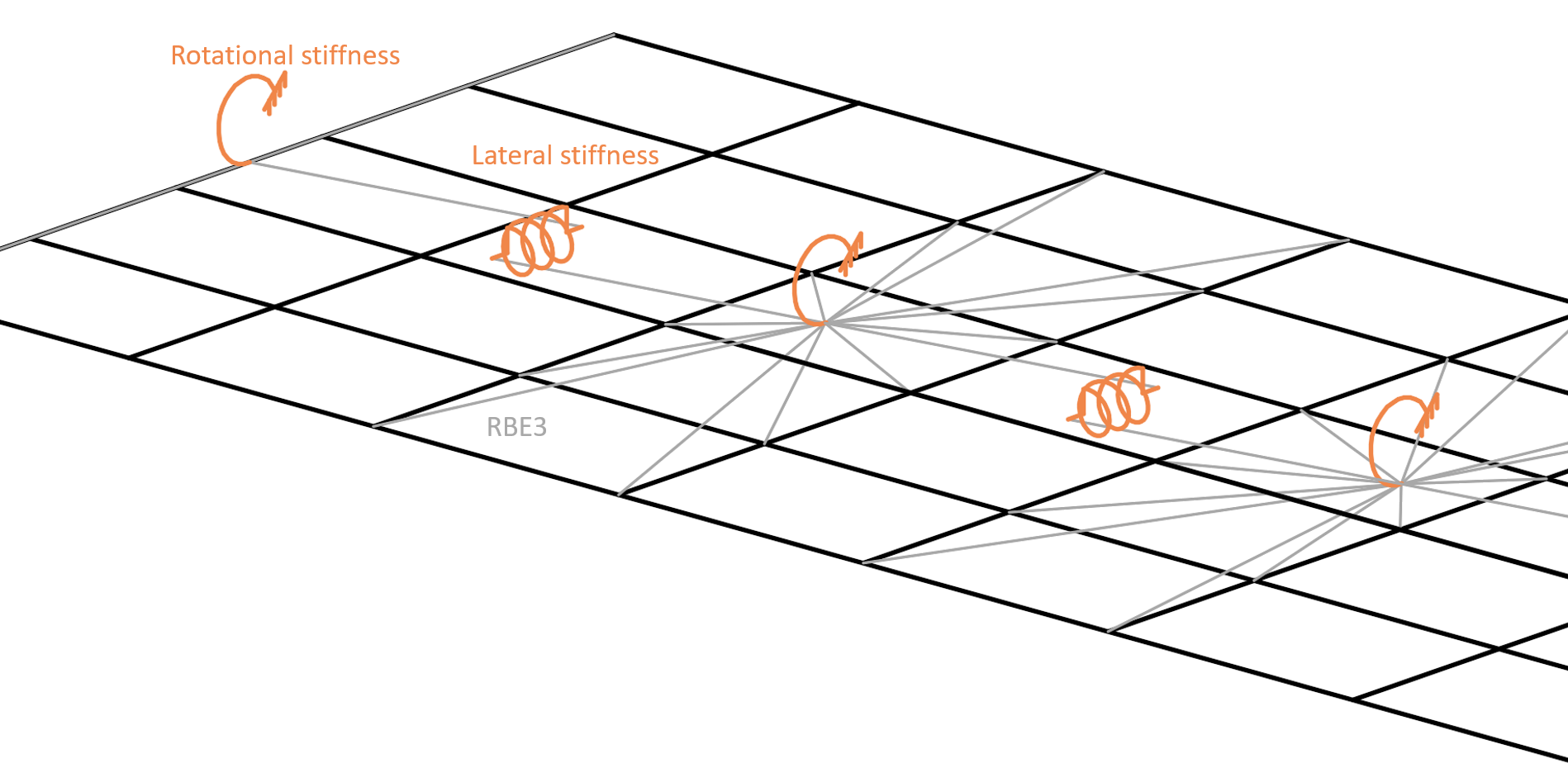
Elementele finite ascunse și RBE3 asigură rigiditatea laterală și torsională a plăcii elementului
De remarcat că RBE3 sunt doar legături de interpolare care nu asigură prin ele însele nicio rigiditate.
Verificare
Un model care asigură LTR a fost verificat cu software-ul LTBeam, care utilizează elemente de bară (1D) cu șapte grade de libertate. Aceasta înseamnă că secțiunea transversală nu se deformează, dar elementul poate surprinde încovoierea neuniformă (warping). Comparația este prezentată pe un exemplu de secțiune transversală IPE 180 din oțel S355 cu o lungime de 6 m. Grinda este încastrată la ambele capete cu o încărcare uniformă de 20 kN/m aplicată pe talpa superioară. Software-ul LTBeam poate determina momentul critic elastic care corespunde rezultatului analizei liniare de flambaj (LBA) în IDEA StatiCa Member.
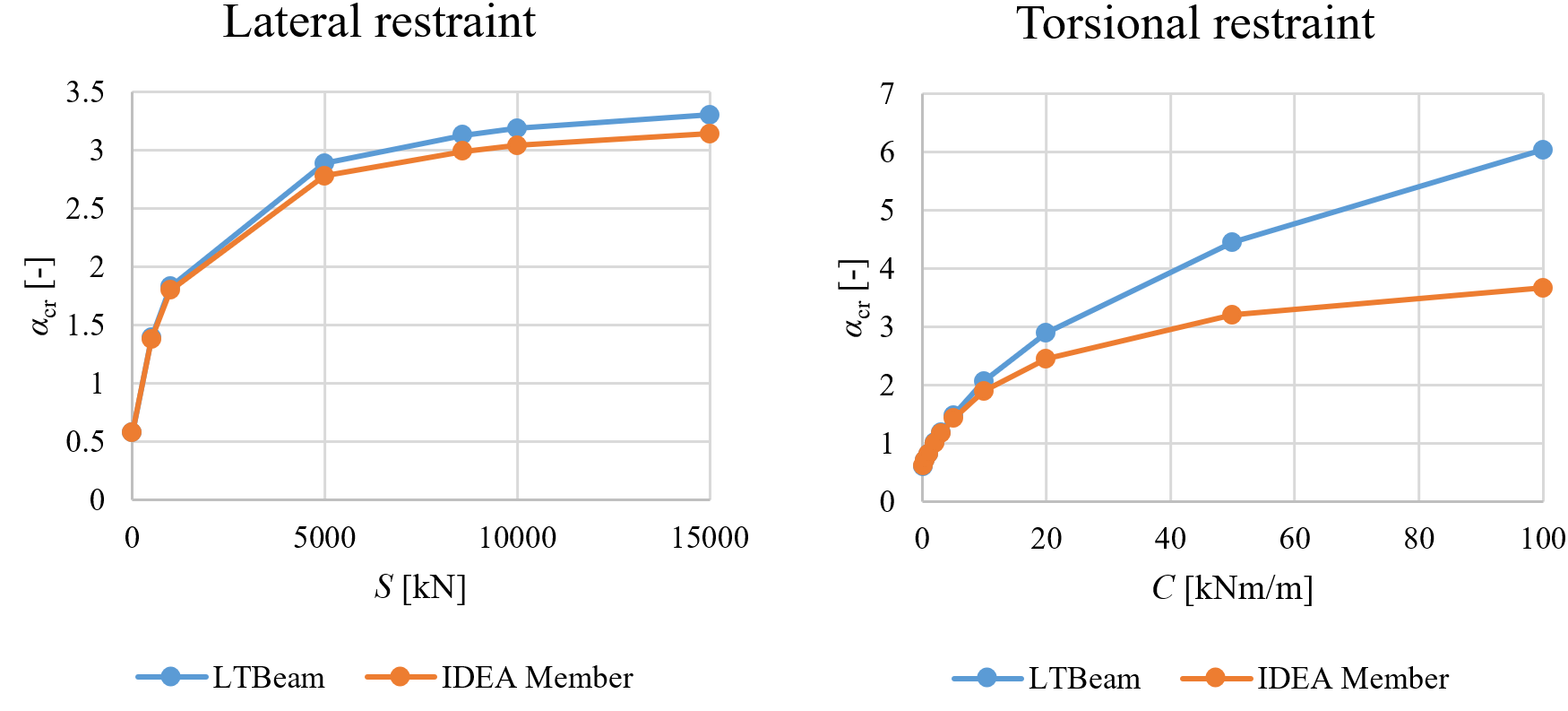
Comparație între LTBeam și IDEA StatiCa Member pentru rigiditate laterală și torsională
Multiplicatorul sarcinii critice la flambaj elastic \(\alpha_{cr}\) cu rigiditate laterală este foarte similar conform ambelor software. Rigiditatea laterală limită la care flambajul lateral-torsional are un efect de cel mult 5 % din rezistența la încovoiere a grinzii este calculată conform EN 1993-1-1 ca Slim = 8 589 kN. Cu toate acestea, rezultatele cu reținere torsională diverg la niveluri mai ridicate de rigiditate la rotație. Observând forma deformată în IDEA StatiCa Member, diferența este cauzată de deformarea secțiunii transversale, care poate fi surprinsă doar de modelul cu elemente de tip placă. LTBeam furnizează multiplicatori ai sarcinii critice nerealiste de mari pentru rigiditate torsională ridicată.
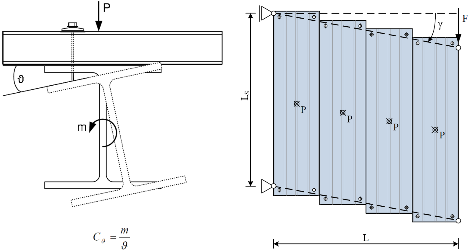
Pentru a verifica această afirmație, modelul cu elemente de tip placă ABAQUS a fost creat la Universitatea ETH. Grinda este din nou încastrată la ambele capete, din oțel S355 și cu o lungime de 6 m. A fost utilizată secțiunea transversală IPE 240. Rigiditatea torsională limită, adică flambajul lateral-torsional are un efect de cel mult 5 % din rezistența la încovoiere a grinzii, a fost calculată ca Clim = 27,13 kNm/m. Modelul este încărcat cu o forță la mijlocul deschiderii pe talpa superioară.
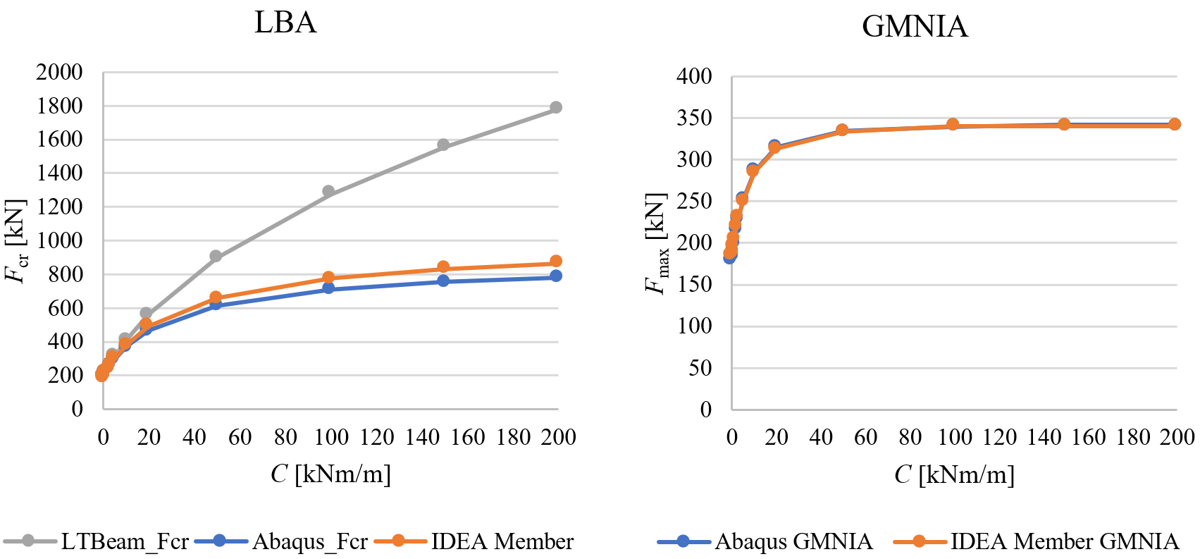
Comparație între ABAQUS, LTBeam și IDEA StatiCa Member pentru rigiditate torsională
Efectul rigidității torsionale este foarte similar în ambele modele realizate cu elemente de tip placă, iar LTBeam diverge. Cel mai important, rezistențele la flambaj furnizate de ABAQUS și IDEA StatiCa Member prin GMNIA coincid aproape perfect – diferențele sunt de până la 4 %.
Estimarea rigidității
LTR asigurată de planșee umplute cu beton și cu acțiune compozită asigurată prin dornuri cu cap poate fi considerată rigidă cel puțin în cazul rigidității laterale. Rigiditățile asigurate de tablele trapezoidale ale panourilor sandwich sunt mult mai mici și pot fi determinate prin experimente sau calcule. Cel mai adesea, valorile rigidității laterale și torsionale vor fi recomandate de producătorii de panouri sandwich sau alte tipuri de placaje.
Calculul rigidității laterale S [N] asigurată de tablele trapezoidale este prevăzut în EN 1993-1-3, Capitolul 10:
\[S=1000 \sqrt{t^3} \left ( 50+10 \sqrt[3]{b_{roof}} \right ) \frac{s}{h_w} \]
unde:
- t – grosimea de calcul a tablei trapezoidale [mm]
- broof – lățimea acoperișului, adică pentru acoperișul în două ape este distanța dintre coamă și streașină [mm]
- s – distanța dintre grinzi [mm]
- hw – înălțimea profilului tablei trapezoidale [mm]
Formula este valabilă dacă tabla trapezoidală este conectată la grindă la fiecare nervură. Dacă tabla este conectată la grindă doar la fiecare a doua nervură, atunci S trebuie înlocuit cu 0,2 S.
Rigiditatea laterală a panourilor sandwich este descrisă în recomandarea ECCS. Rigiditatea dispozitivelor de fixare este esențială:
\[S=\frac{k_v}{2B} \sum_{k=1}^{n_k}c_k^2\]
unde:
- kv – rigiditatea la forfecare a unui dispozitiv de fixare
- B – lățimea unui panou sandwich
- nk – numărul de perechi de dispozitive de fixare pe panou și reazem
- ck – distanța dintre cele două dispozitive de fixare ale unei perechi
Rigiditatea torsională este mai complexă și poate fi estimată și prin recomandarea ECCS. Aceasta include contribuția dispozitivelor de fixare, a panoului sandwich și a distorsiunii grinzii. Distorsiunea grinzii poate fi neglijată deoarece este deja inclusă în modelul cu elemente de tip placă.
Rigiditatea torsională (în stânga) și laterală (în dreapta) asigurate de panourile sandwich (ECCS, 2014)
În practica americană, reținerea împotriva flambajului lateral-torsional este de obicei considerată completă sau neglijabilă în funcție de tipul și orientarea tablelor de planșeu. De exemplu, Tabelul 8.1 din AISC Seismic Design Manual identifică condițiile de reținere pentru grinzile supuse compresiunii axiale. Cu toate acestea, acolo unde este necesar, rigiditatea laterală poate fi derivată din rigiditatea diafragmei, G', calculată conform AISI S310. Denavit et al. (2020) prezintă o metodă de calcul al rigidității torsionale.
Referințe
- CTICM, LTBeam v. 1.0.11, disponibil la: https://www.cesdb.com/ltbeam.html
- Abaqus. Manual de referință, versiunea 6.16. Simulia, Dassault Systéms. Franța, 2016.
- EN 1993-1-3: Eurocode 3: Proiectarea structurilor de oțel – Partea 1-3: Reguli generale – Reguli suplimentare pentru elemente și table formate la rece, CEN, 2006.
- ECCS TC7 – Grupul Tehnic de Lucru TWG 7.9 Panouri Sandwich și Structuri Conexe, Recomandări Europene privind Stabilizarea Structurilor Metalice prin Panouri Sandwich, ediția a 2a, 2014. ISBN 978-90-6363-081-2
- Denavit, M.D.; Jacobs, W.P.; Helwig, T.A. (2020). "Continuous Bracing Requirements for Constrained-Axis Torsional Buckling," Engineering Journal, American Institute of Steel Construction, Vol. 57, pp. 69-89.