Flambaj lateral-torsional al unei grinzi cu elemente de rigidizare transversale
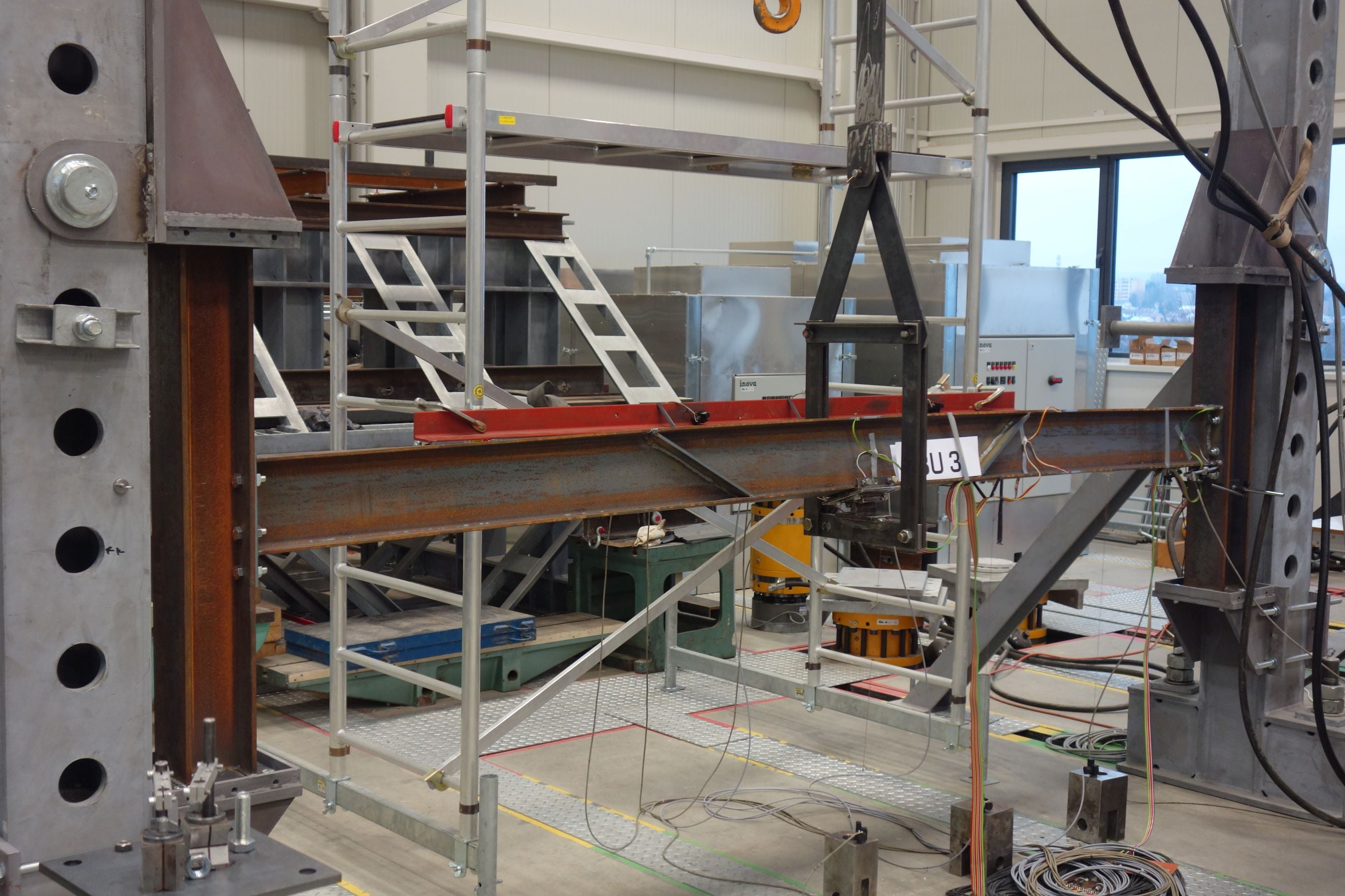
Acest studiu de verificare a fost realizat pentru aplicația IDEA StatiCa Member. Scopul a fost de a asigura că rezultatele LBA și GMNIA sunt corecte și că toate elementele de tip coajă și elementele finite ale componentelor funcționează corect. Geometria modelelor a fost bazată pe experimente efectuate la Centrul AdMaS din cadrul Universității Tehnice din Brno.
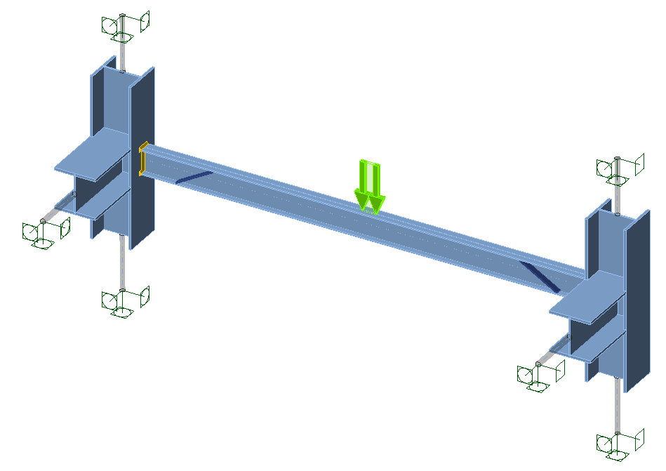
Modelele numerice au fost create în ANSYS, un software comercial de uz general pentru analiza cu elemente finite. A fost utilizată o grindă IPE 180 cu o lungime de 3,3 m din oțel S235. Au fost investigate două condiții la limită:
- Încastrat – toate nodurile de la un capăt sunt încastrate (toți gradele de libertate sunt blocate), celălalt capăt este identic, cu excepția faptului că deplasarea în direcția longitudinală a grinzii este permisă
- Articulat – doar nodurile inimii grinzii sunt blocate (rotația laterală este permisă; la un capăt, toate deplasările sunt blocate, iar la celălalt capăt, deplasarea în direcția longitudinală a grinzii este permisă)
Elementele de rigidizare au fost înclinate la 60 de grade față de axa verticală. Cele două elemente de rigidizare au fost plasate simetric, cu distanță mutuală variabilă. Nu au fost modelate suduri; nodurile plaselor vecine au fost direct îmbinate.
În ANSYS, au fost efectuate analiza statică liniară, analiza liniară de flambaj și analiza geometrică și material neliniară cu imperfecțiuni. Imperfecțiunile au fost egale cu L/300, unde L este lungimea elementului (3,3 m).
Deformația plastică poate fi observată în imaginea următoare:

Modelele corespunzătoare au fost create în IDEA StatiCa Member. Secțiunea transversală a elementelor aferente a fost aleasă ca fiind foarte mare și scurtă în comparație cu grinda analizată, astfel încât să nu influențeze rezultatele.

Comparația rezultatelor este prezentată în tabelul de mai jos. FRd este rezistența la flambaj lateral-torsional determinată prin GMNIA, wy este săgeata laterală la mijlocul deschiderii grinzii la sarcina maximă atinsă, iar Fcr este sarcina critică de flambaj determinată prin LBA. Pozițiile elementelor de rigidizare indică poziția X a elementului de rigidizare față de nodul stâng în IDEA StatiCa Member.
| GMNIA | LBA | ||||||
| FRd [kN] | FRd [kN] | wy [mm] | wy [mm] | Fcr [kN] | Fcr [kN] | ||
| Condiții la limită | Poziții elemente de rigidizare | ANSYS | MEMBER | ANSYS | MEMBER | ANSYS | MEMBER |
| Încastrat | 1550,2050 | 56.79 | 56.97 | 22.07 | 23.30 | 104.4 | |
| 1250,2350 | 61.56 | 63.27 | 21.36 | 21.40 | 121.5 | ||
| 550,3050 | 60.21 | 60.84 | 18.46 | 19.70 | 122.4 | ||
| Articulat | 1550,2050 | 38.39 | 40.77 | 33.69 | 36.10 | 57.0 | 55.8 |
| 1250,2350 | 41.52 | 43.92 | 32.60 | 30.40 | 64.8 | 63.9 | |
| 550,3050 | 44.01 | 47.07 | 22.40 | 23.60 | 82.6 | 81 |
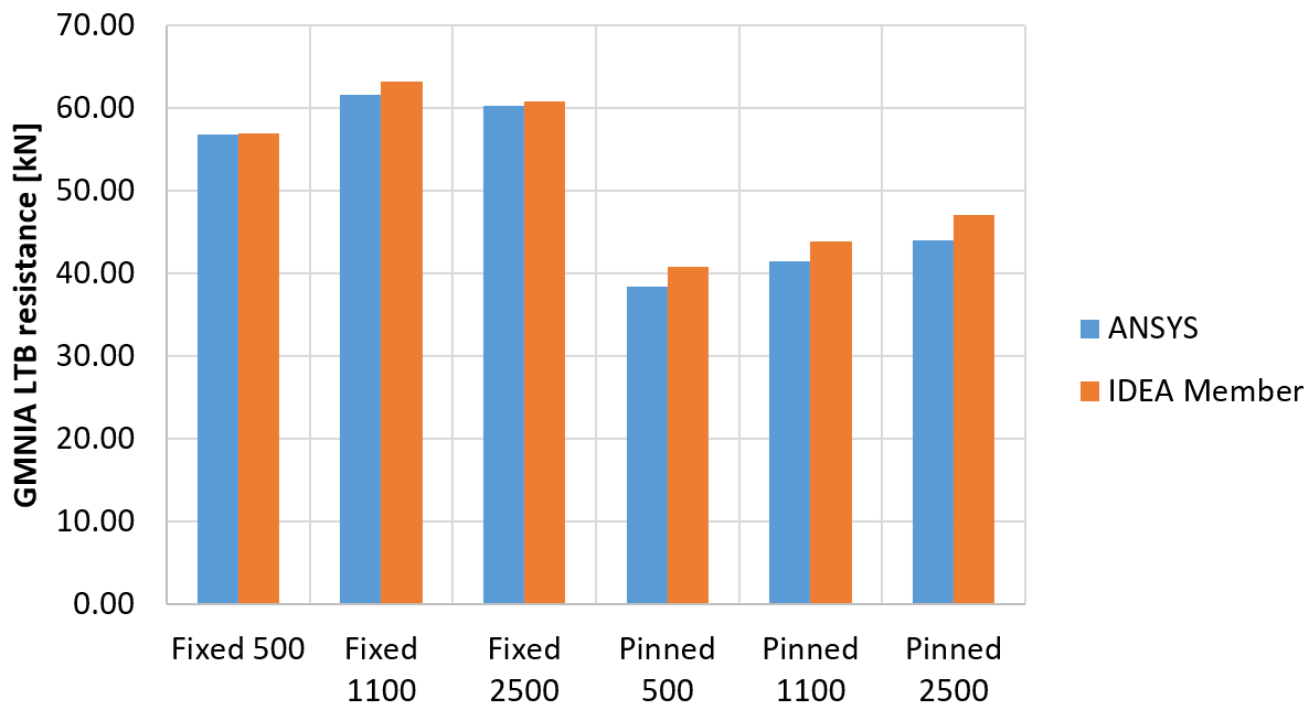
Rezultatele ambelor pachete software corespund îndeaproape. IDEA Member furnizează o sarcină critică de flambaj ușor mai mică și o rezistență la flambaj lateral-torsional ușor mai mare.
Diferența este cauzată în principal de modelarea elementelor de rigidizare. În Ansys, nodurile sunt îmbinate la liniile mediane ale plăcilor, însă în Member, elementul de rigidizare este mai scurt. Acesta se termină la suprafața plăcii, iar golul este umplut cu suduri. Rezultatul este că placa mai scurtă din IDEA Member este ușor mai rigidă decât cea mai lungă din Ansys.