
Pilar articulado com armadura (ACI)
1 Iniciar um novo projeto
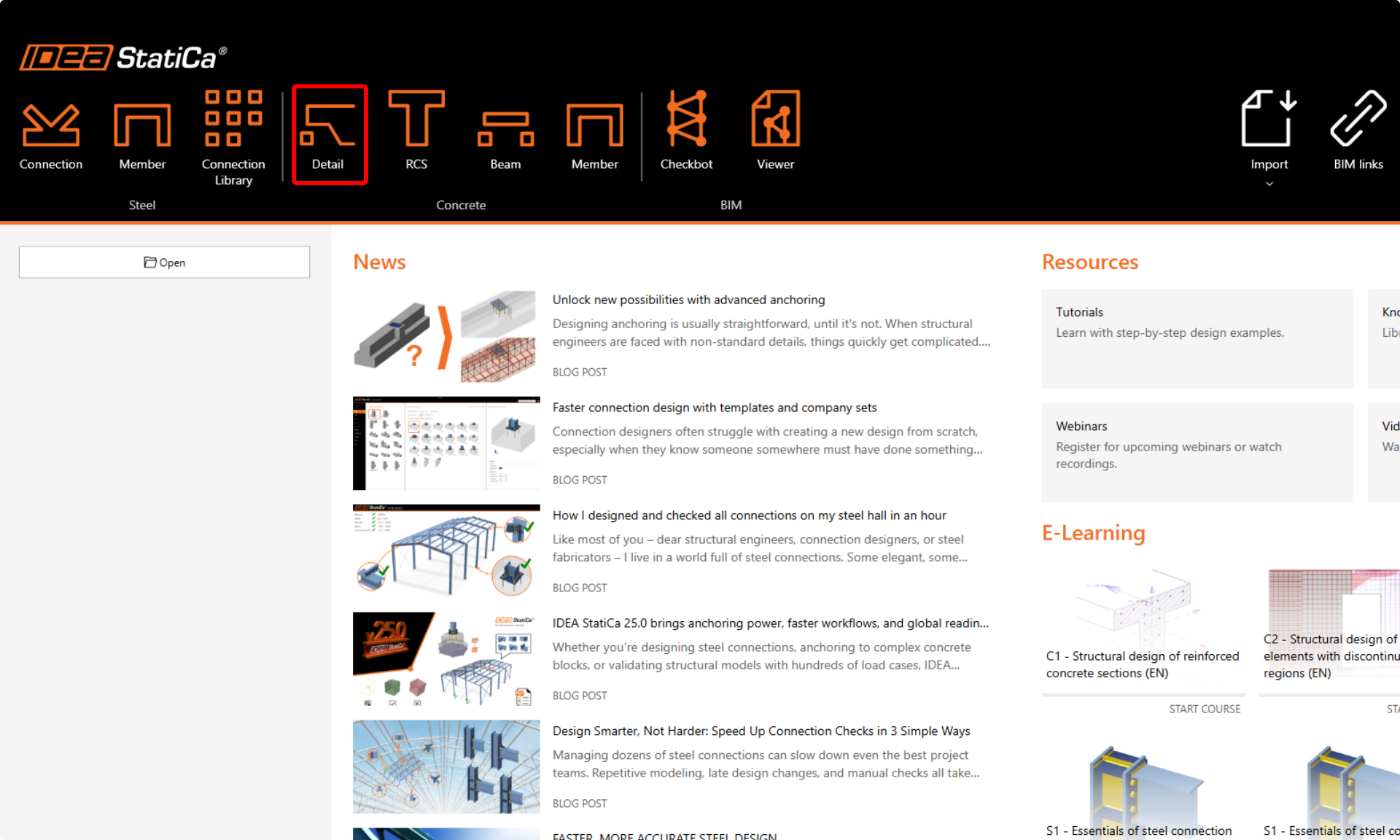
Vamos iniciar a aplicação IDEA StatiCa Detail (descarregue a versão mais recente). Na janela principal do IDEA StatiCa, abra a aplicação Detail para iniciar um novo projeto.
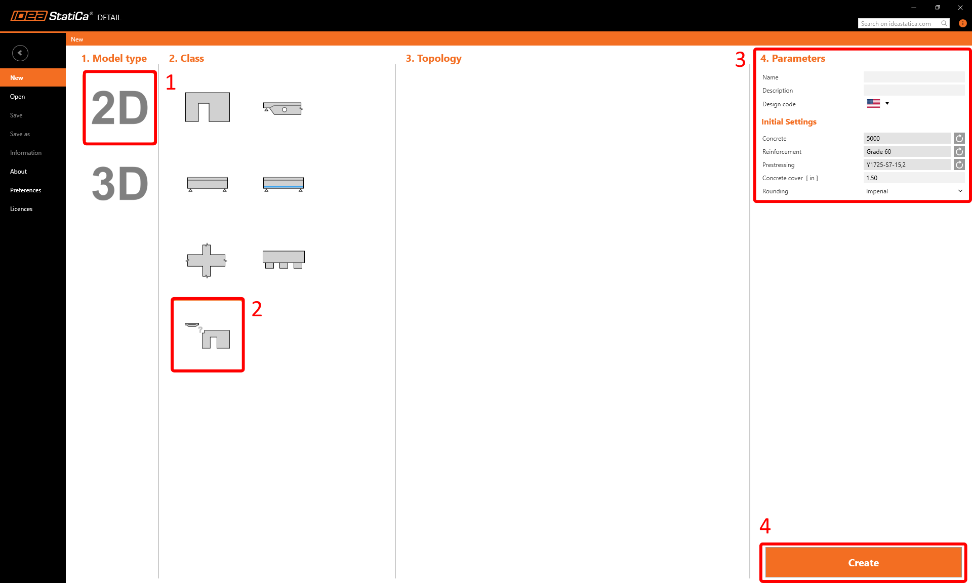
Neste tutorial, criaremos um pilar articulado de raiz, pelo que deve escolher a opção de iniciar sem utilizar um modelo. No entanto, os modelos podem ser muito úteis para os seus projetos futuros.
Neste passo, define também o código de dimensionamento (escolha ACI), bem como a classe do betão e o cobrimento (utilize betão 5000 e cobrimento 1,50 in). Pode alterar a sua escolha de material (ou adicionar outro) posteriormente. No entanto, o código de dimensionamento só pode ser escolhido neste primeiro passo do projeto.
2 Geometria
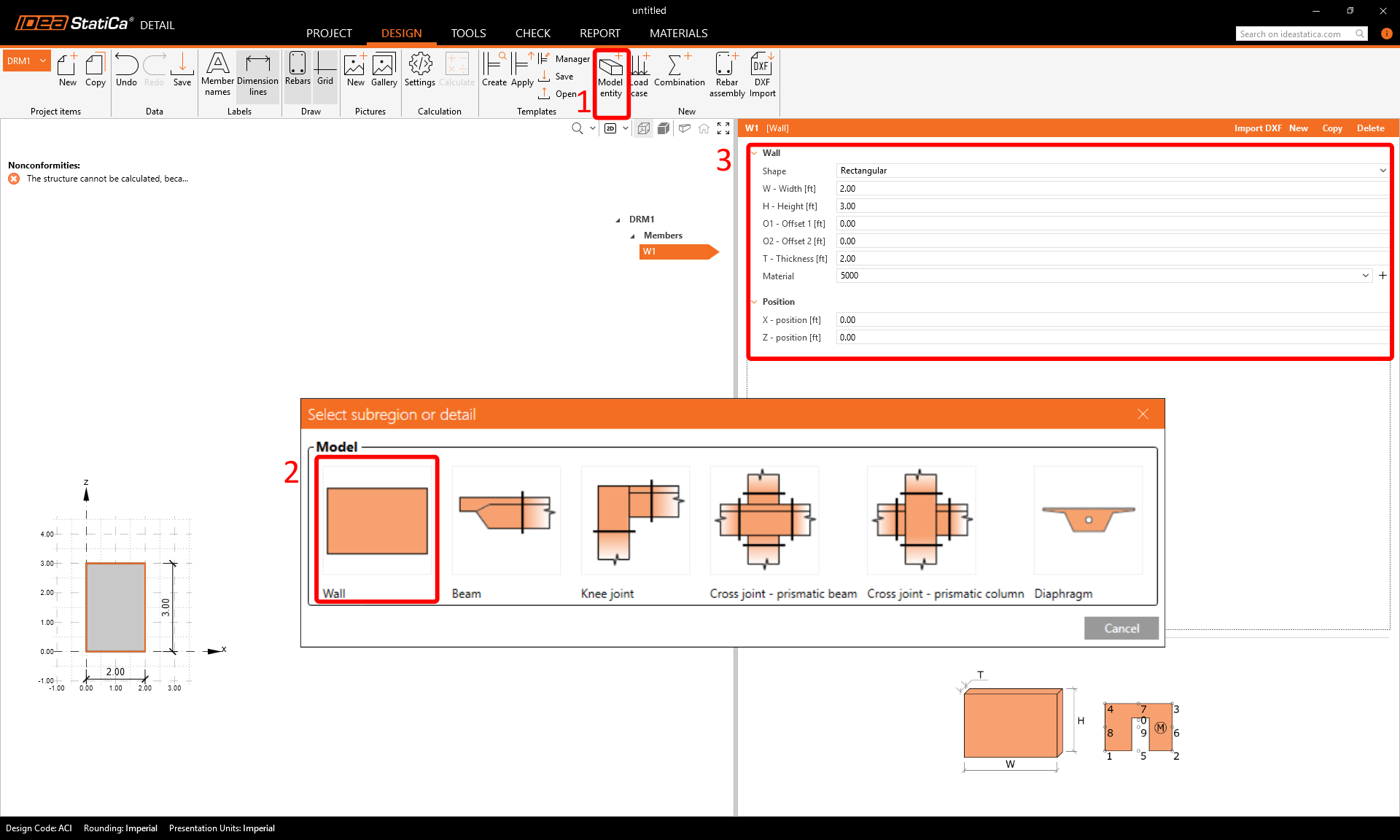
A aplicação Detail abrirá com o separador Design automaticamente selecionado. Pode definir novos itens utilizando os comandos na faixa de opções superior e, em seguida, editar esses itens no menu em árvore. Se pretender conhecer melhor o ambiente da aplicação, consulte o seguinte artigo - Interface geral na aplicação Detail.
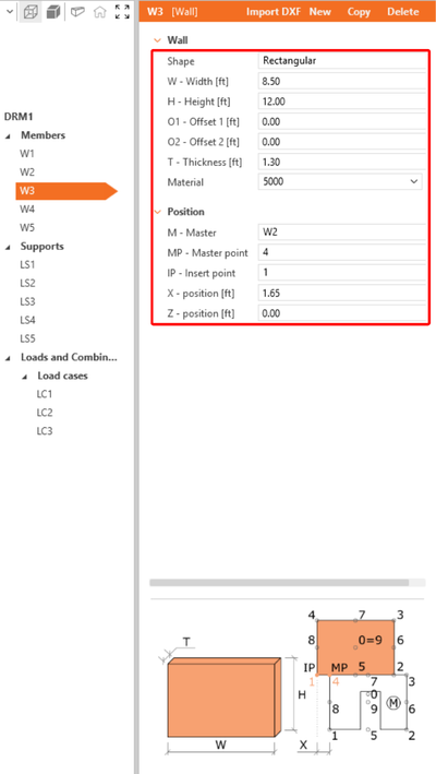
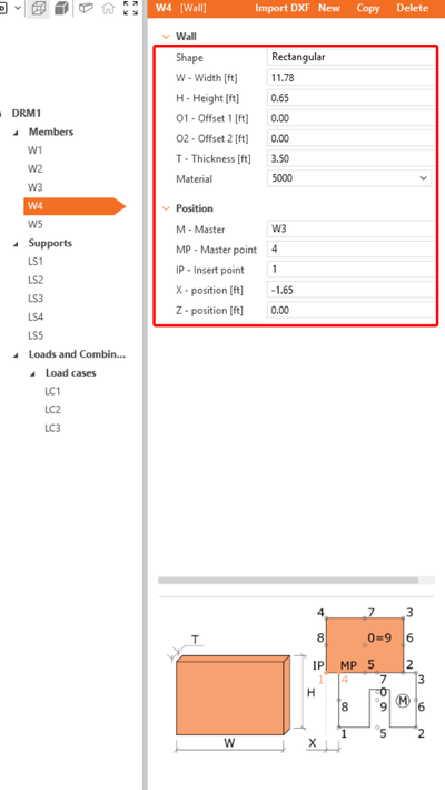
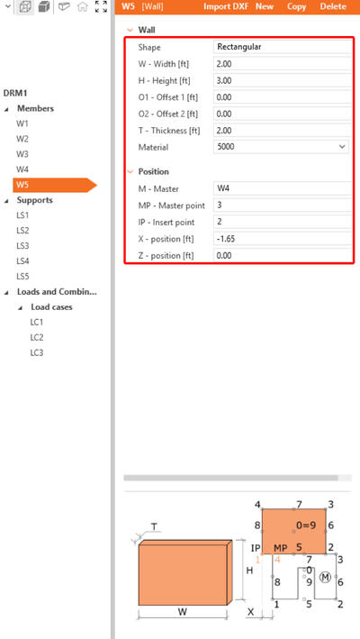
Começaremos por criar os Elementos. Utilize o botão na faixa de opções superior para adicionar uma nova entidade ao modelo - Parede. Em seguida, edite as dimensões e a posição da parede conforme indicado na imagem.
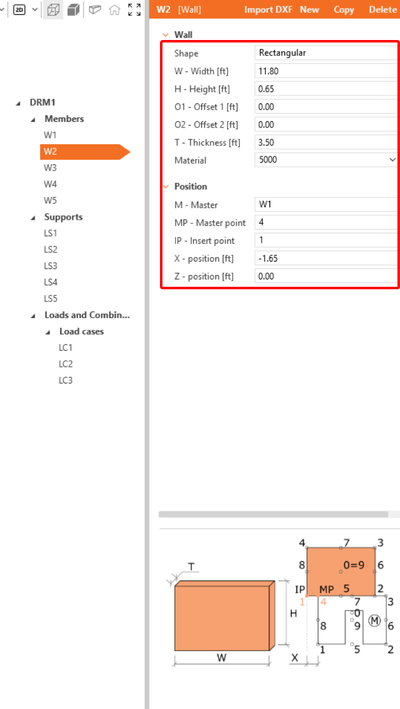
Repita este processo para criar as entidades de parede adicionais W2-W5.
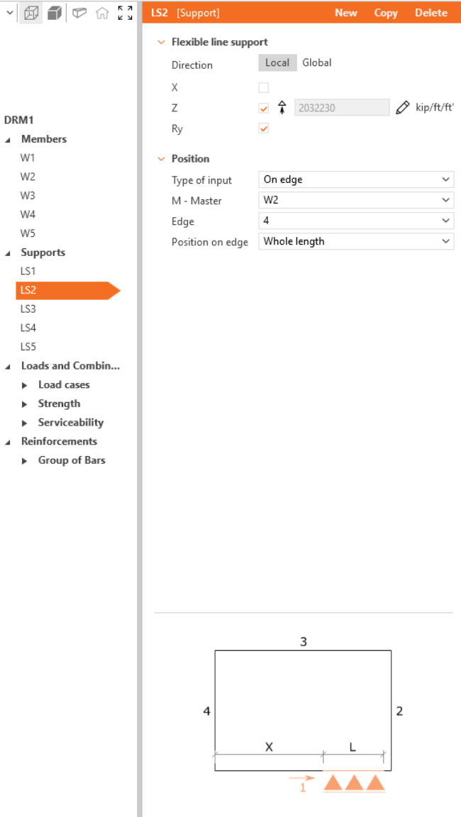
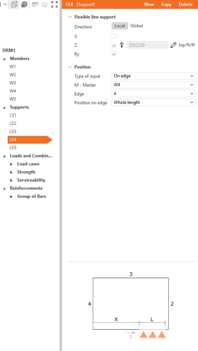
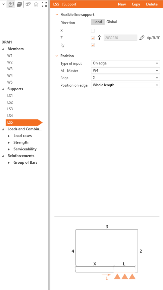
Para concluir a geometria, adicione apoios. Novamente, insira uma nova entidade no modelo - desta vez escolha Apoio de linha.
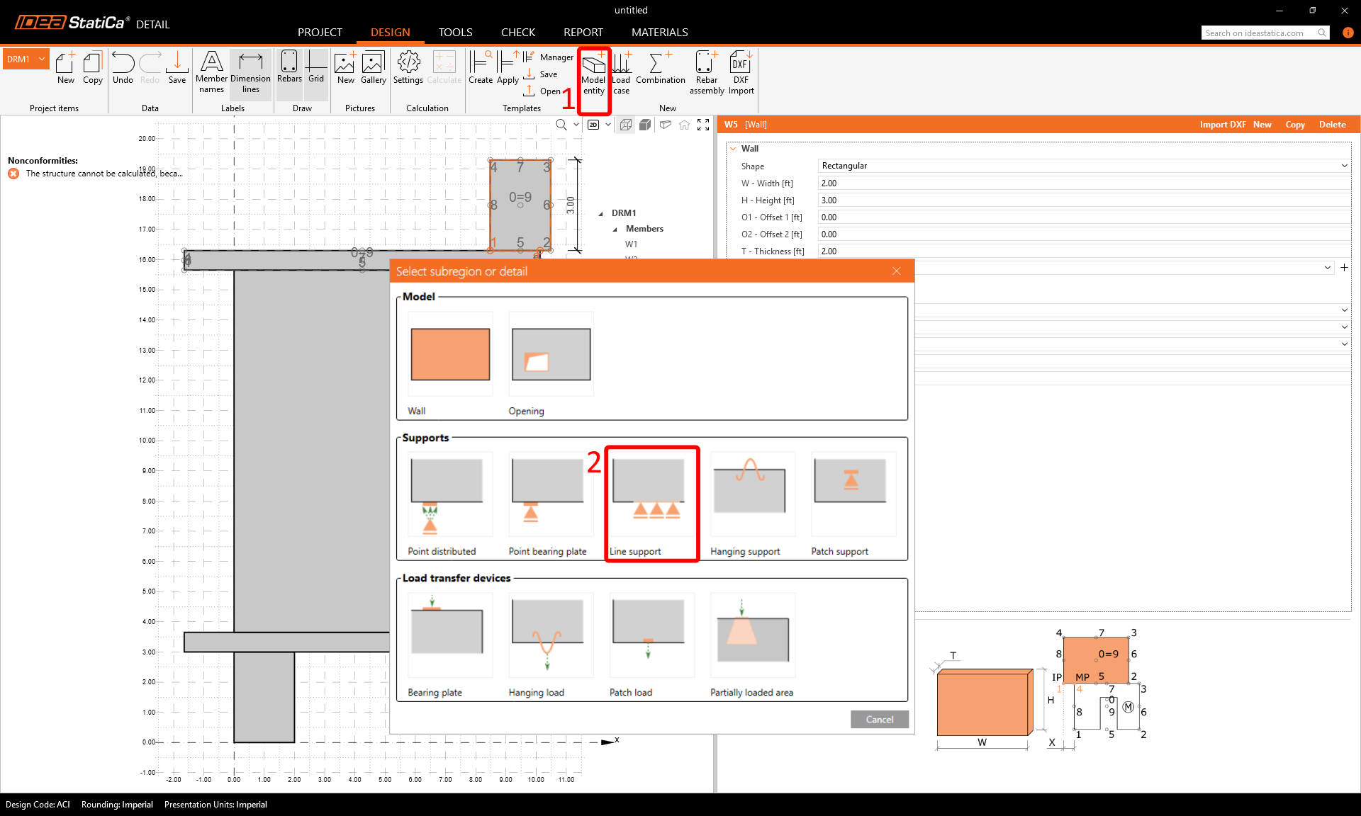
Tal como na criação das paredes, defina os parâmetros de acordo com a imagem e repita para LS2-LS5.


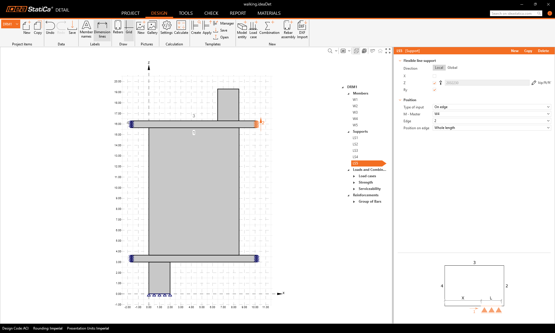
A geometria final deverá agora ter o seguinte aspeto:
3 Ações e Combinações
Para adicionar uma ação, clique em Caso de carga na faixa de opções. É criado um caso de carga LC1. Utilize o botão mais (+) para inserir um impulso de carga dentro deste caso de carga — escolha Carga Pontual e repita adicionando outro impulso de carga com Peso Próprio. Crie mais dois casos de carga LC2 e LC3 apenas com impulsos de Carga Pontual.
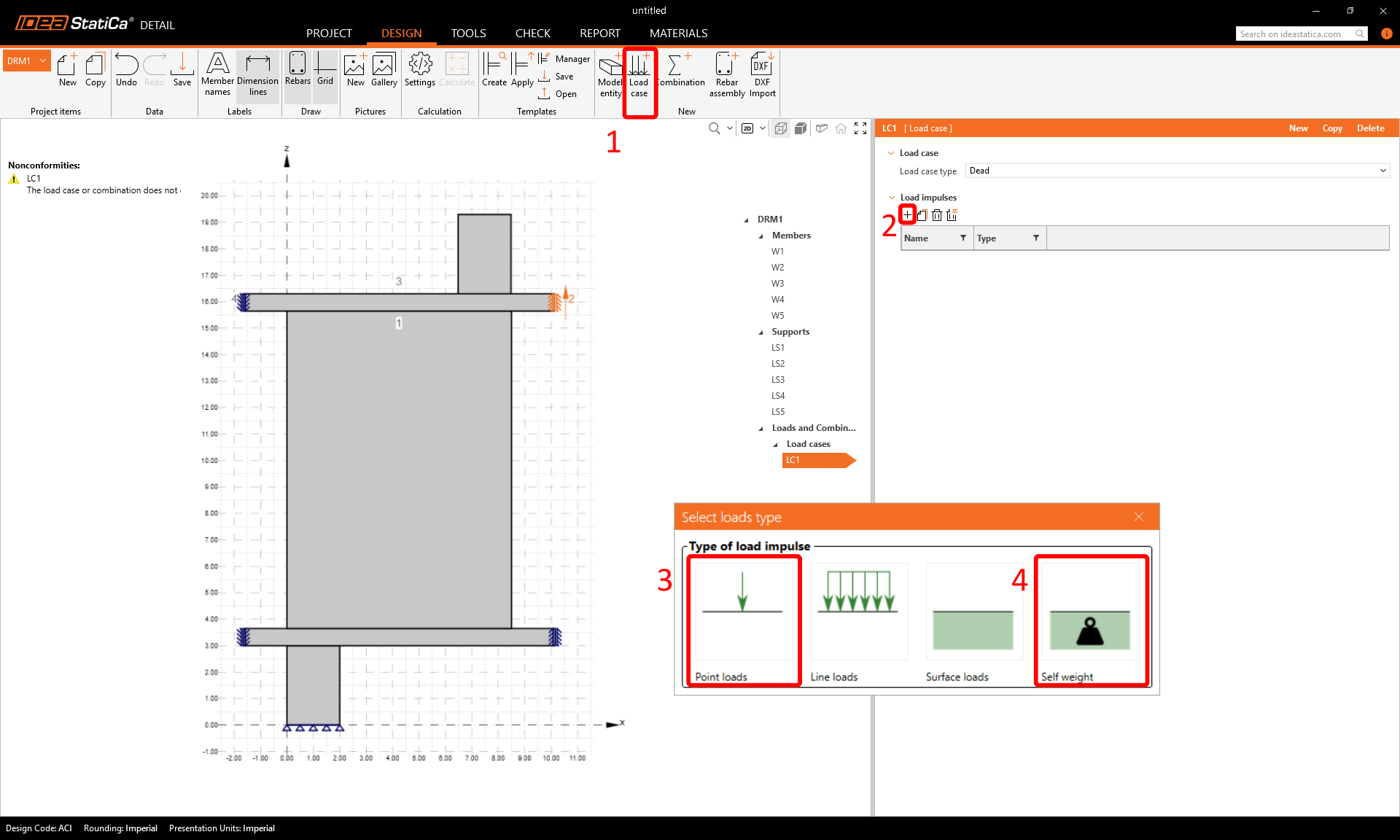
Para poder distinguir entre efeitos de curta e longa duração, certifique-se de que atribui corretamente os tipos de caso de carga Permanente e Variável e introduz os valores da força de carga pontual F e as posições das forças pontuais de acordo com as imagens.


As combinações de ações podem ser criadas a partir do comando Combinação na faixa de opções superior. Adicione seis combinações C1-C6 e, em seguida, clique no ícone de lápis para editar os fatores de combinação.
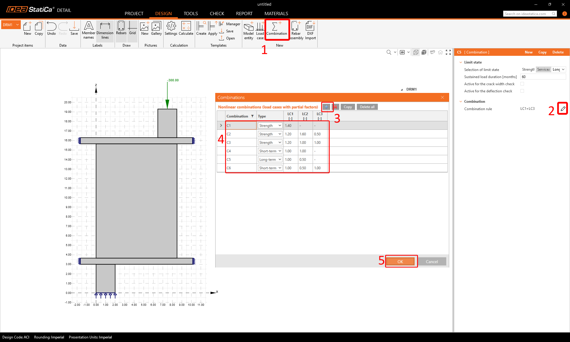
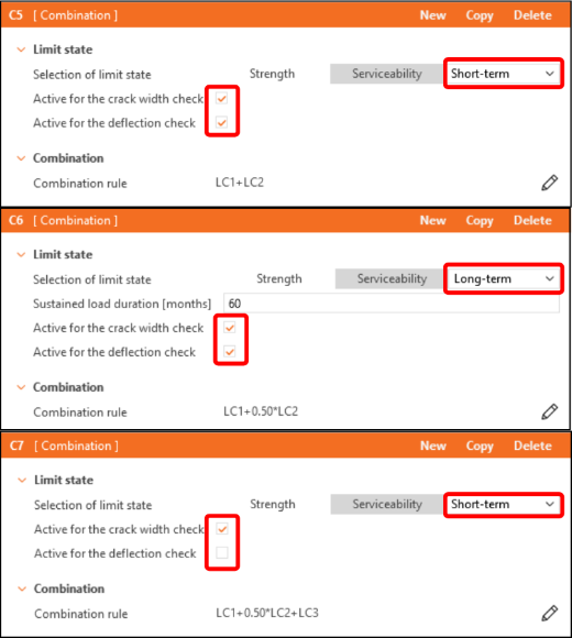
Na lista em árvore, as combinações estão divididas em grupos de Resistência (C1-C3) e Utilização em Serviço (C4-C6). Para ativar as verificações de largura de fenda ou de deformação, marque as caixas de verificação correspondentes na janela de propriedades em Combinações de Utilização em Serviço (C4-C6).
4 Armadura
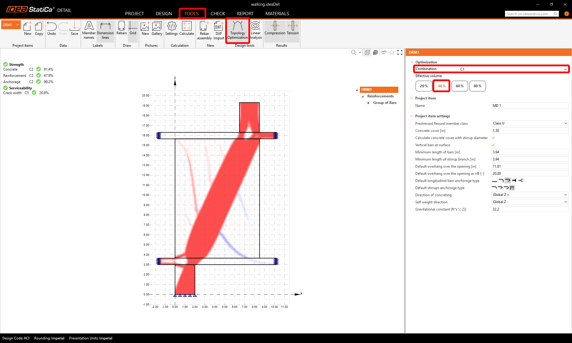
O passo seguinte consiste em armar o modelo. Em primeiro lugar, podemos mudar para o separador Ferramentas e iniciar a Otimização Topológica em Ferramentas de dimensionamento, que ajudam a projetar a armadura (em alternativa, pode utilizar a Análise Linear).
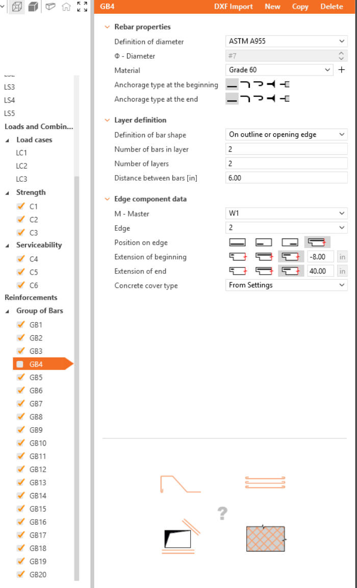
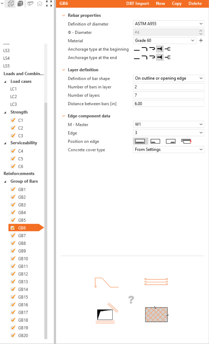
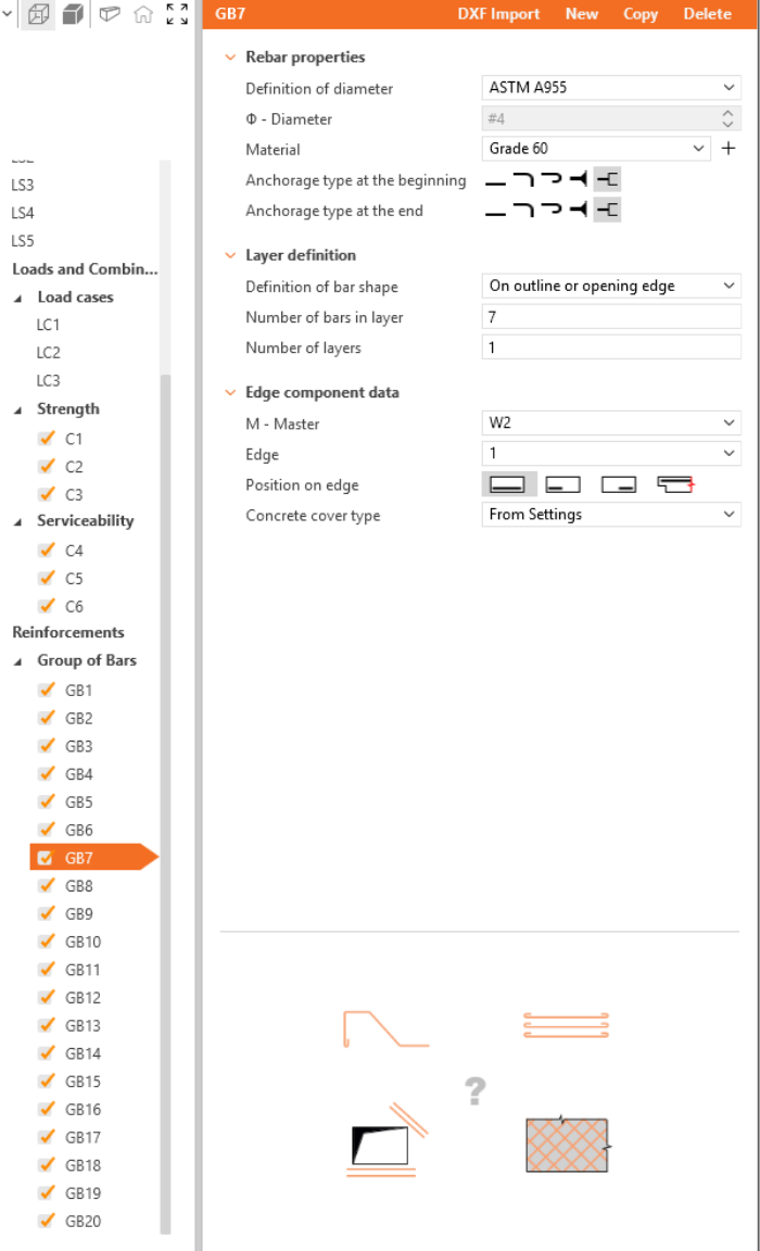
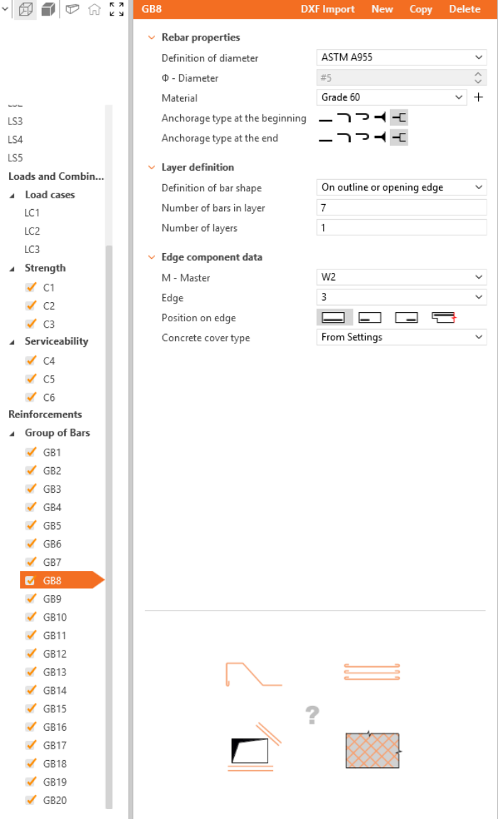
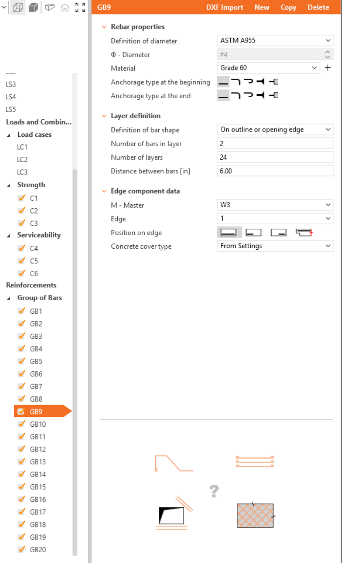
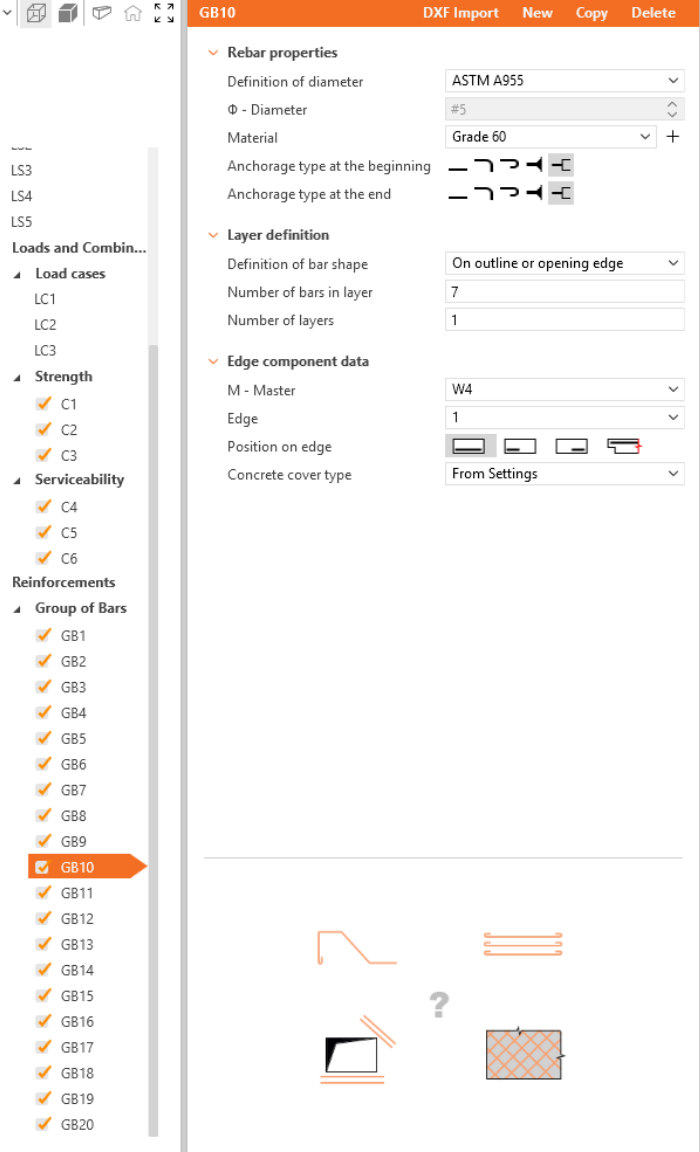
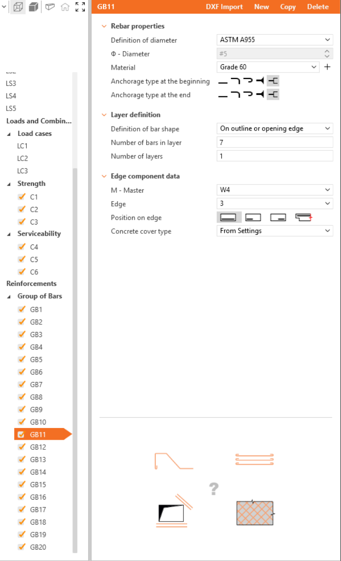
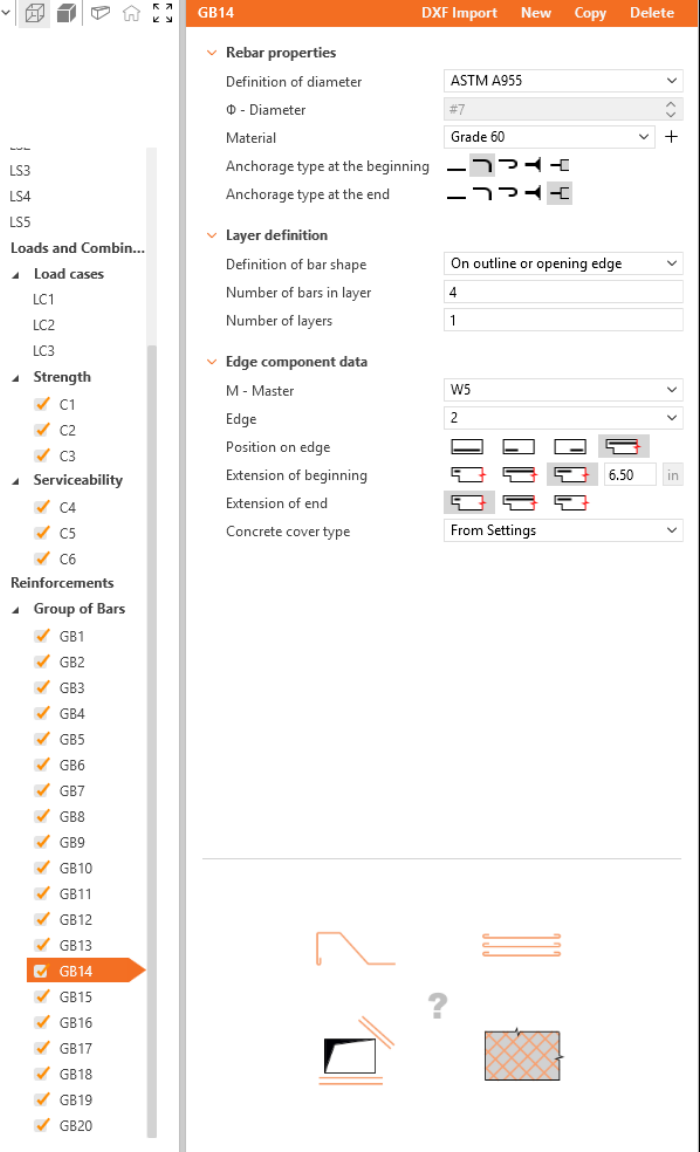
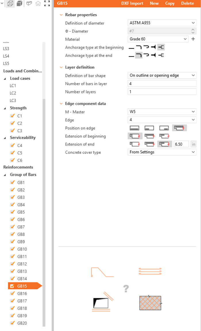
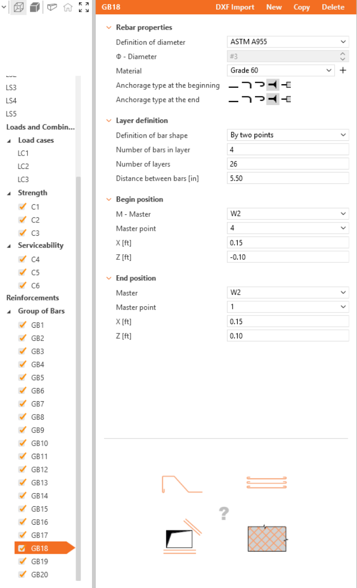
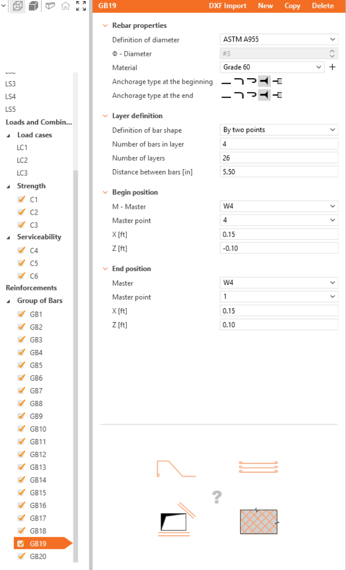
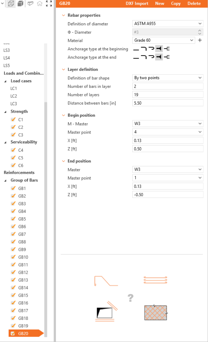
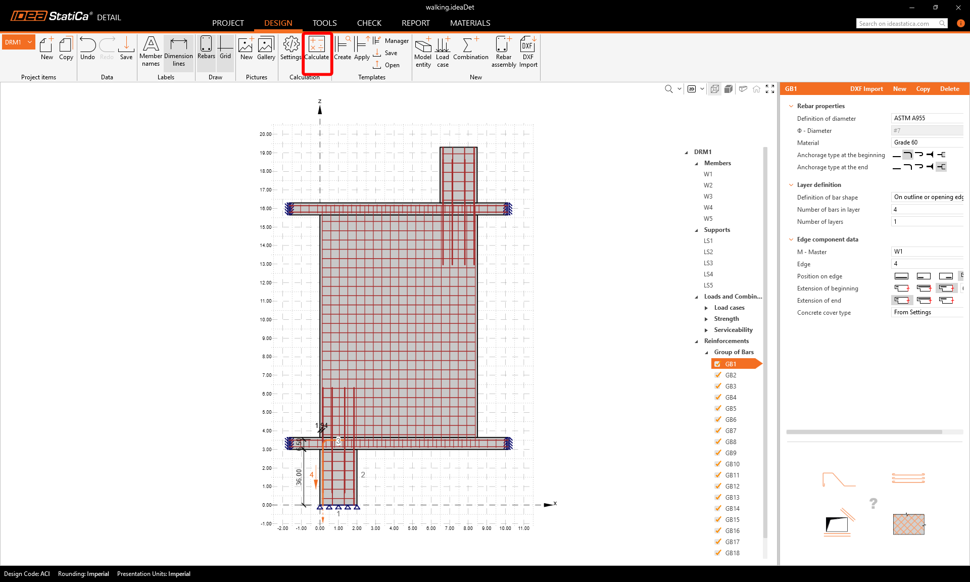
Agora projete a armadura. Clique em Conjunto de armadura na secção Novo. Selecione o tipo de armadura Grupo de varões.
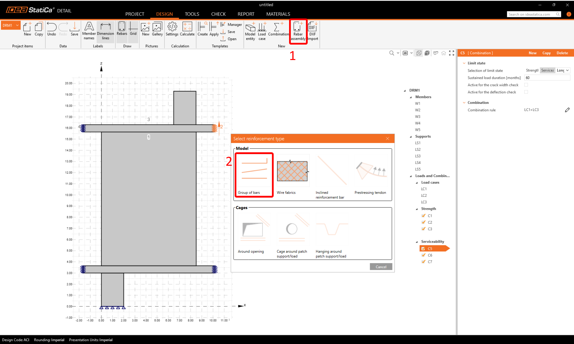
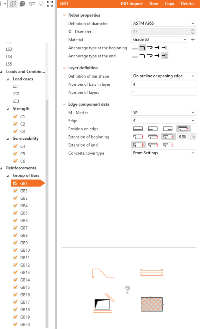
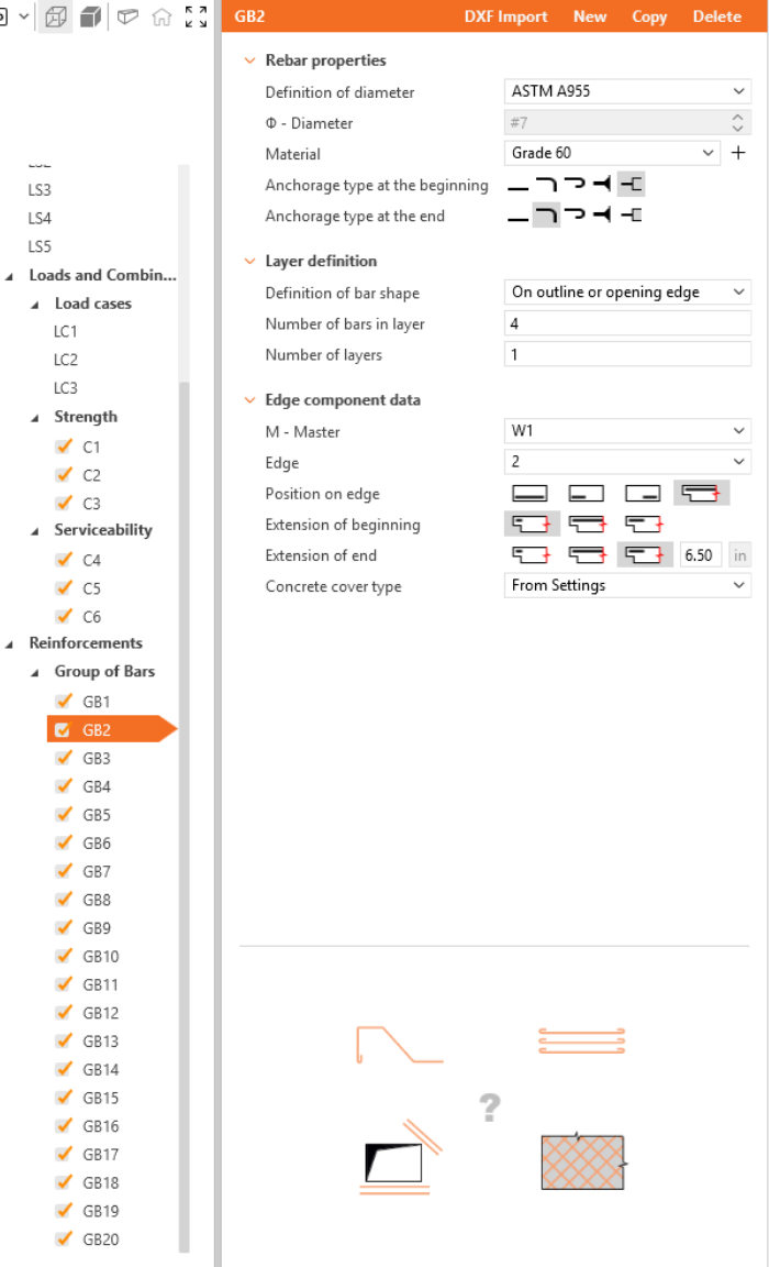
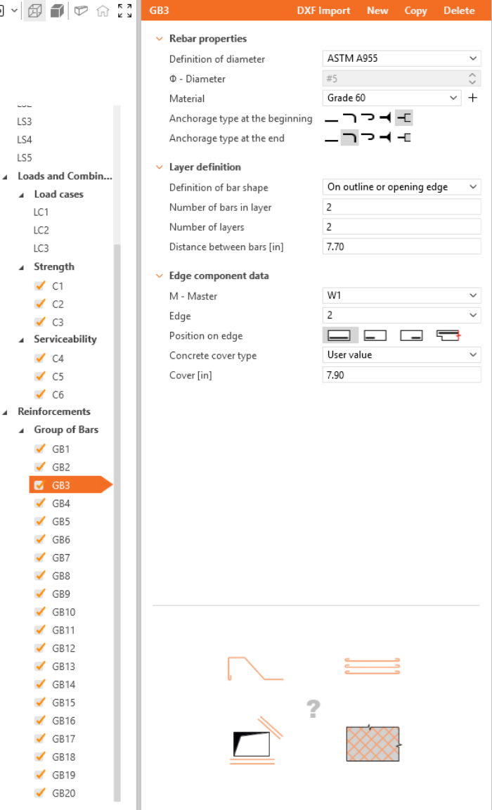
Defina as propriedades de GB1 e repita para GB2 a GB20. Também pode utilizar Copiar para copiar a armadura atual.


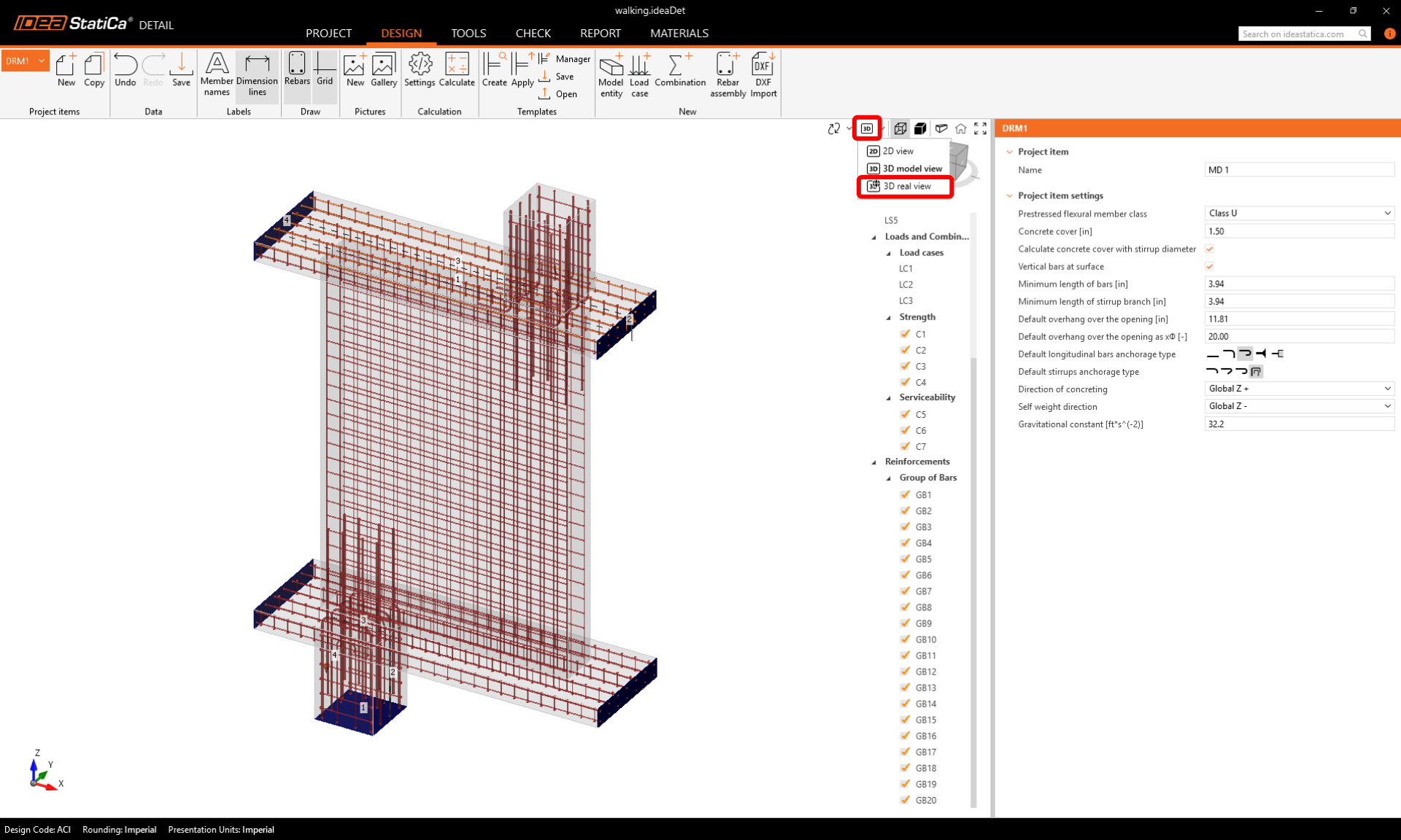
Para uma verificação final, volte ao separador Design e escolha a Vista 3D Real para inspecionar visualmente o alinhamento dos varões.
5 Cálculo e Verificação
Inicie a análise clicando no botão Calcular na faixa de opções.
O modelo de análise é gerado automaticamente. Navegue até Verificação. À esquerda, pode ver os resultados globais, como a utilização dos materiais.
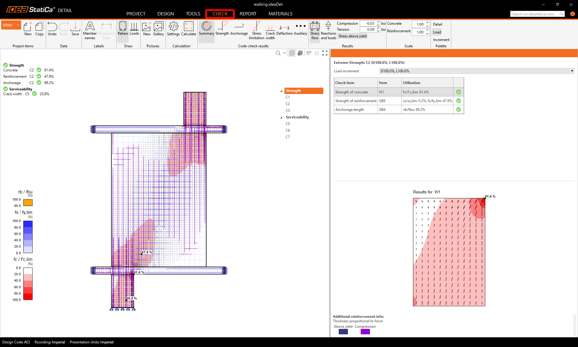
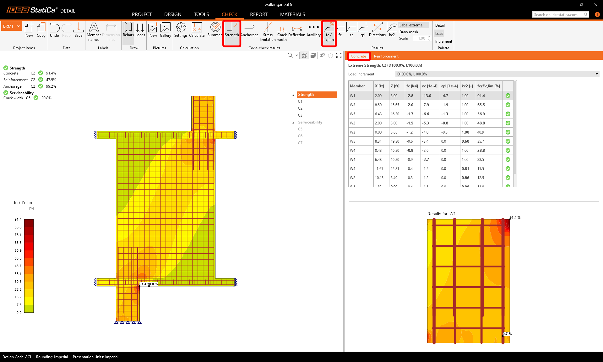
Para analisar as verificações detalhadas de cada componente, comece pela Resistência. Isto mostrará as verificações do betão, como a utilização em tensão, a direção das tensões principais e das deformações principais, que podem ser ativadas na faixa de opções. Também pode alterar as direções e a escala das tensões.
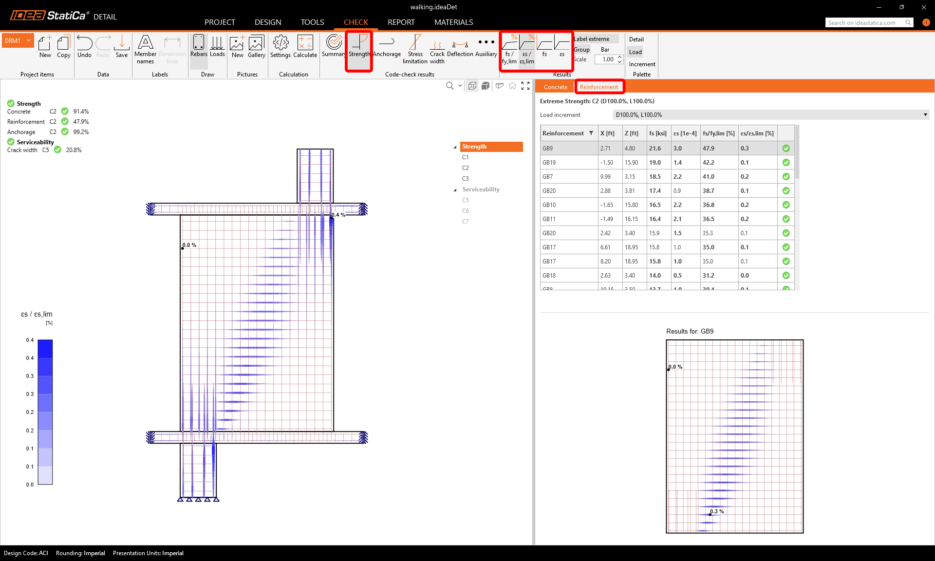
Para resultados detalhados da armadura, é necessário mudar para o separador Armadura. Isto alterará os ícones da faixa de opções e também expandirá a tabela de resultados. Pode visualizar os resultados das deformações e tensões em cada varão e a respetiva utilização.
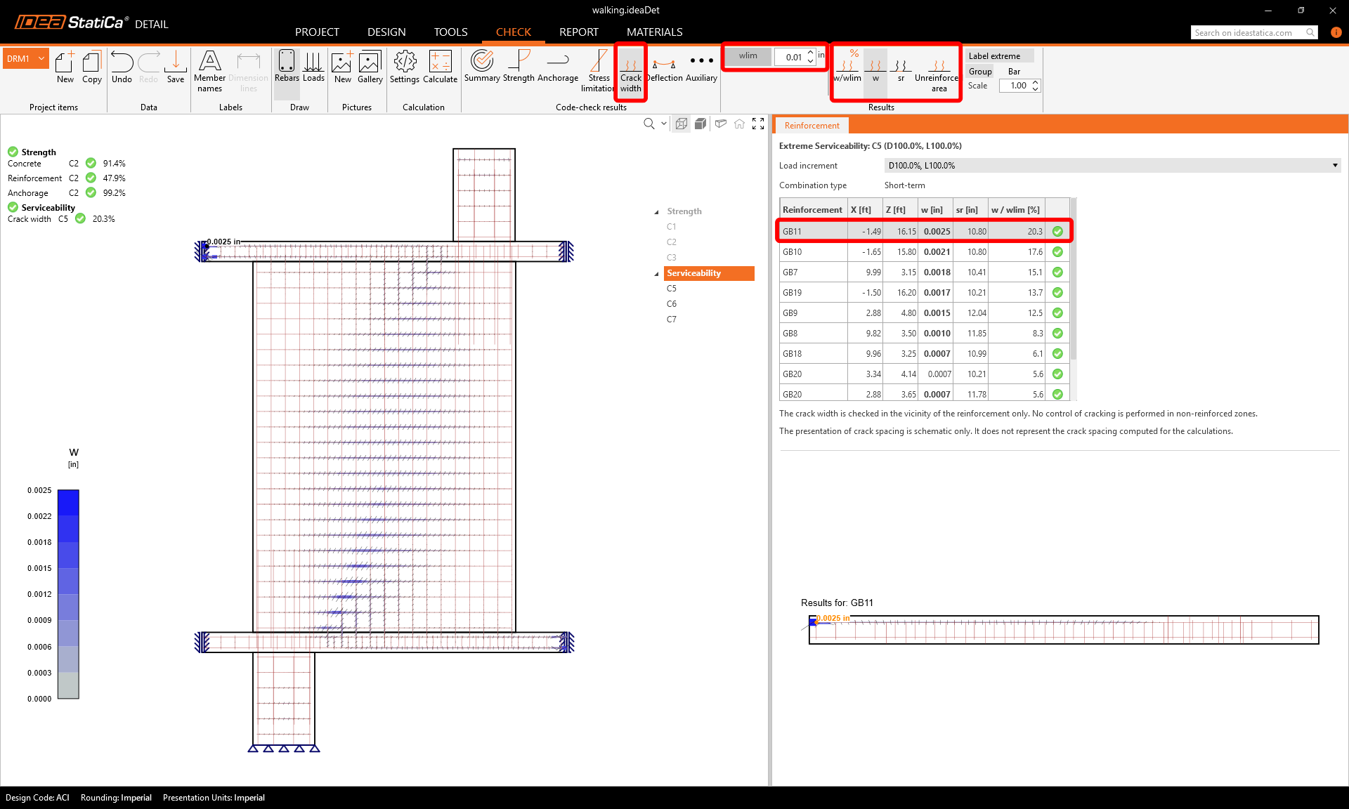
Vamos à verificação de Limitação de fendilhação. Para além dos ícones para alternar entre os resultados, existem definições na faixa de opções para especificar o valor limite.
6 Impressão do relatório
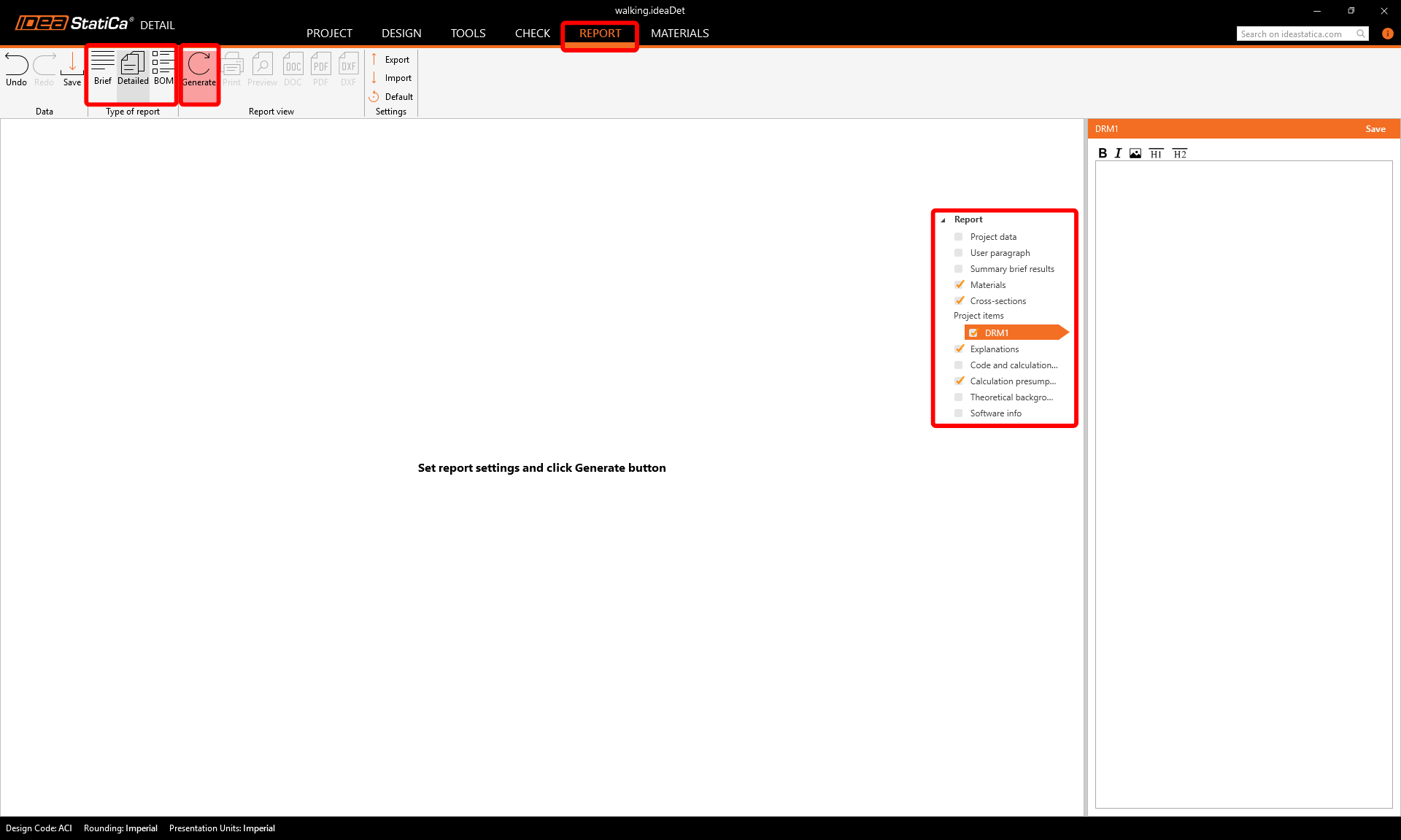
Chegou o momento de imprimir um relatório dos seus cálculos. Vá ao separador Relatório. Pode escolher o tipo de relatório Resumido ou Detalhado e ajustar ainda mais o relatório de acordo com as suas necessidades no menu em árvore. Selecione as opções pretendidas e prima Gerar na faixa de opções superior.
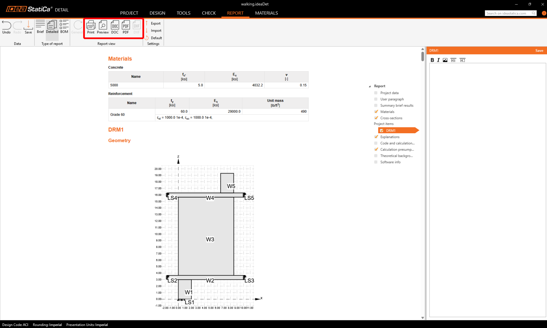
O relatório é gerado e podemos guardá-lo como PDF ou exportá-lo para um ficheiro aberto do Microsoft Word.
Projetou, otimizou e efetuou a verificação normativa do pilar articulado com armadura.