
Bewehrte Gehstütze (ACI)
1 Starten eines neuen Projekts
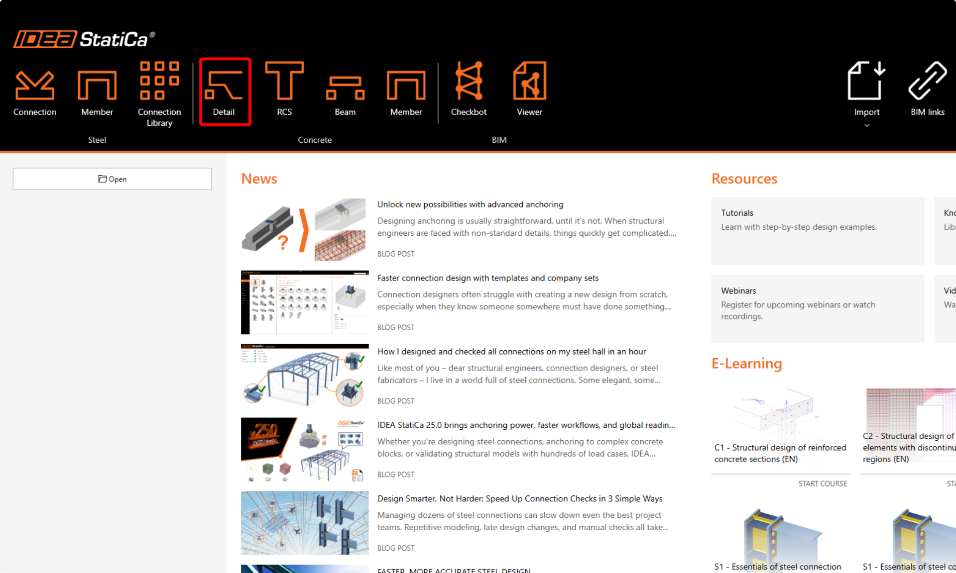
Starten wir die IDEA StatiCa Detail-Anwendung (laden Sie die neueste Version herunter). Öffnen Sie im Hauptfenster von IDEA StatiCa die Detail-Anwendung, um ein neues Projekt zu starten.
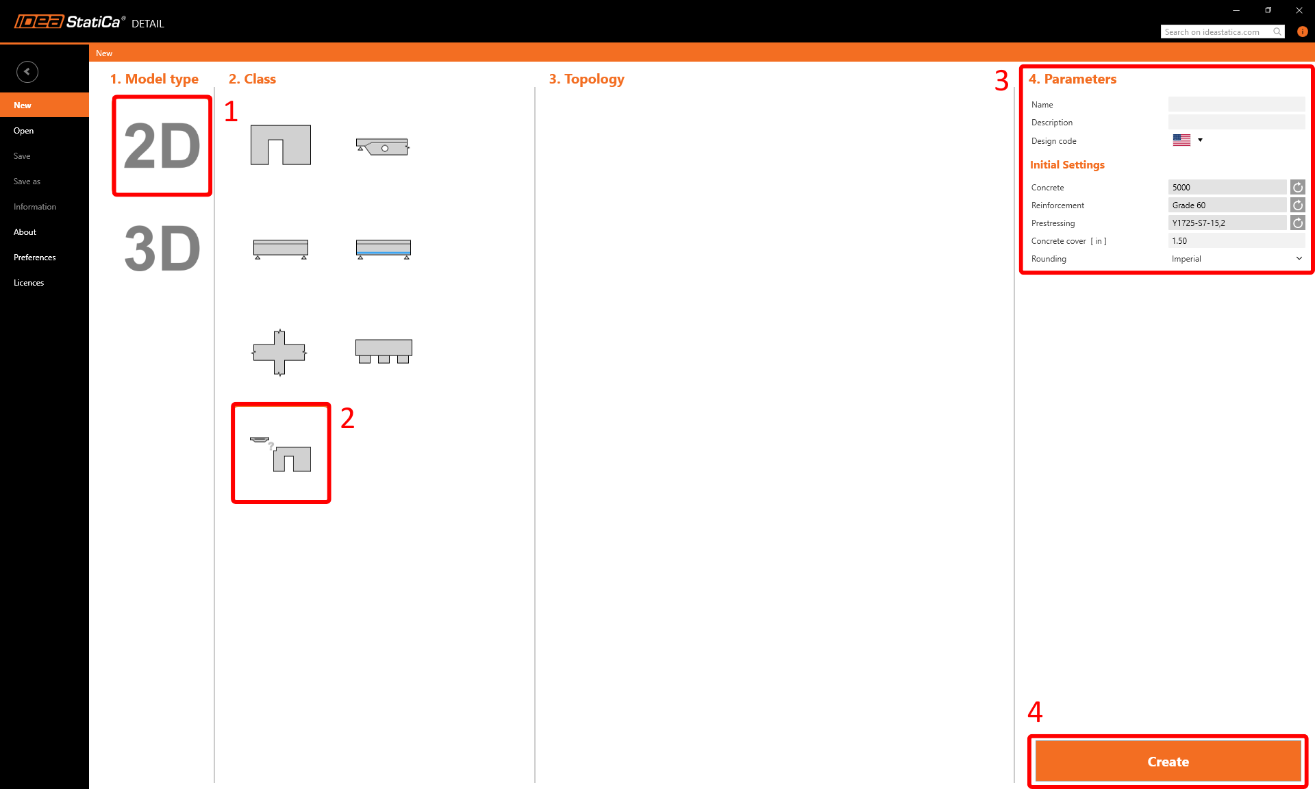
In diesem Tutorial erstellen wir eine Gehstütze von Grund auf. Wählen Sie daher die Option, ohne Vorlage zu beginnen. Vorlagen können jedoch für Ihre zukünftigen Bemessungen sehr hilfreich sein.
In diesem Schritt legen Sie auch die Bemessungsnorm fest (wählen Sie ACI) sowie die Betonklasse und die Betondeckung (verwenden Sie Beton 5000 und Betondeckung 1,50 in). Sie können Ihre Materialauswahl später ändern (oder ein weiteres Material hinzufügen). Die Bemessungsnorm kann jedoch nur in diesem ersten Schritt des Projekts gewählt werden.
2 Geometrie
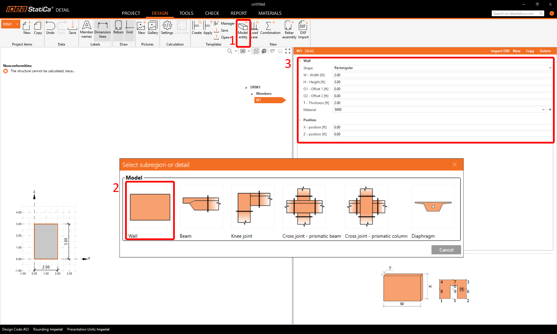
Die Detail-Anwendung wird mit der automatisch ausgewählten Registerkarte Design geöffnet. Sie können neue Elemente über Befehle im oberen Menüband definieren und diese anschließend im Strukturbaum bearbeiten. Wenn Sie die Anwendungsumgebung besser kennenlernen möchten, lesen Sie den folgenden Artikel: Allgemeine Benutzeroberfläche in der Detail-Anwendung.
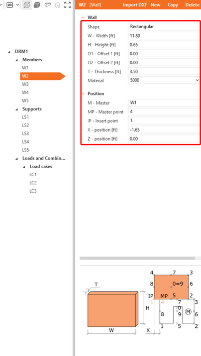
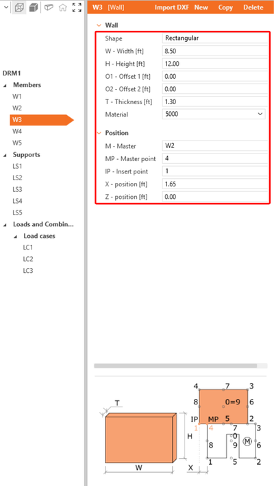
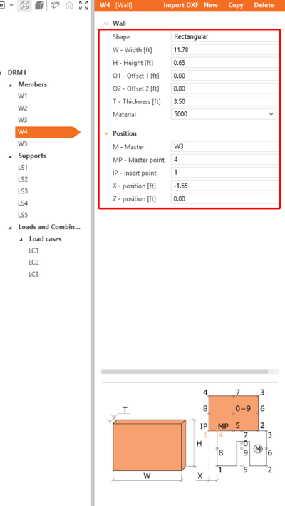
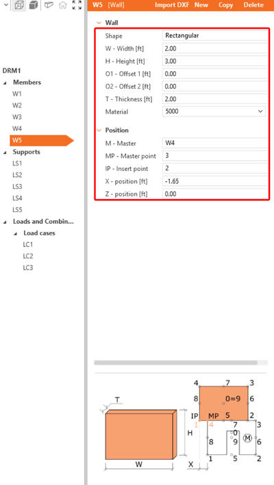
Wir beginnen mit der Erstellung der Bauteile. Verwenden Sie die Schaltfläche im oberen Menüband, um ein neues Modellelement hinzuzufügen – Wand. Bearbeiten Sie dann die Abmessungen und die Position der Wand wie im Bild gezeigt.
Wiederholen Sie diesen Vorgang, um die weiteren Wandelemente W2–W5 zu erstellen.
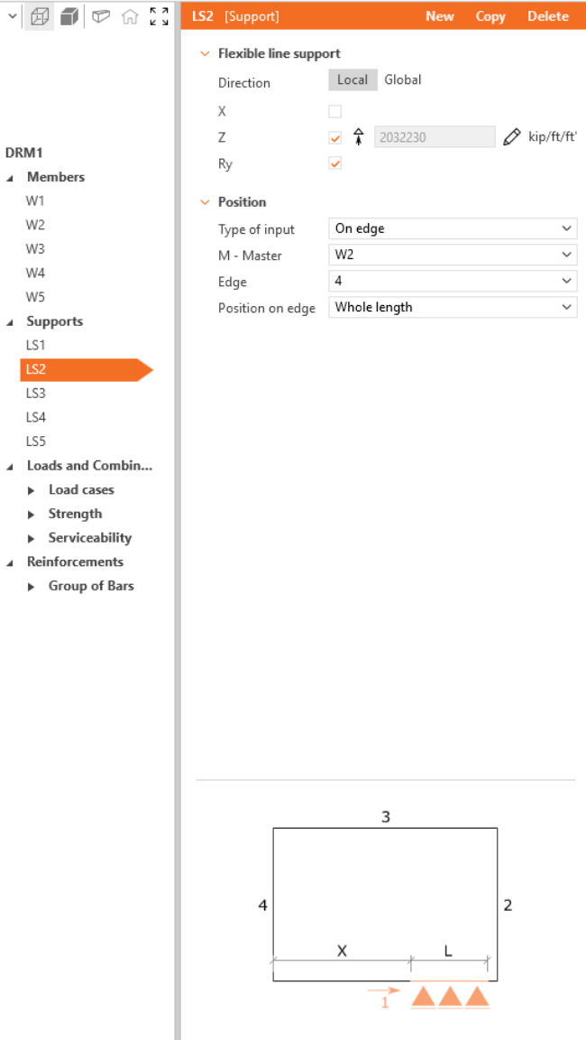
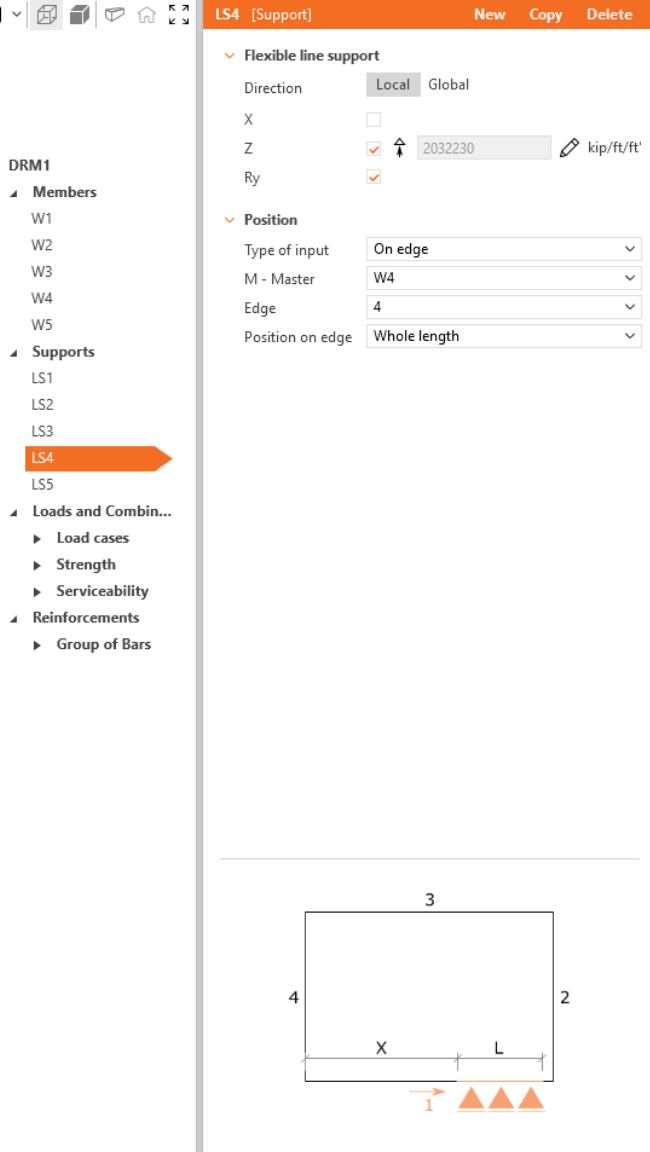
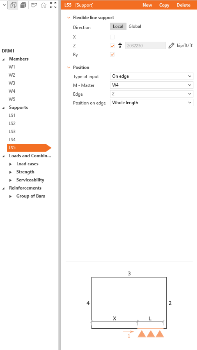
Um die Geometrie abzuschließen, fügen Sie Lager hinzu. Fügen Sie erneut ein neues Modellelement ein – wählen Sie diesmal Linienlager.
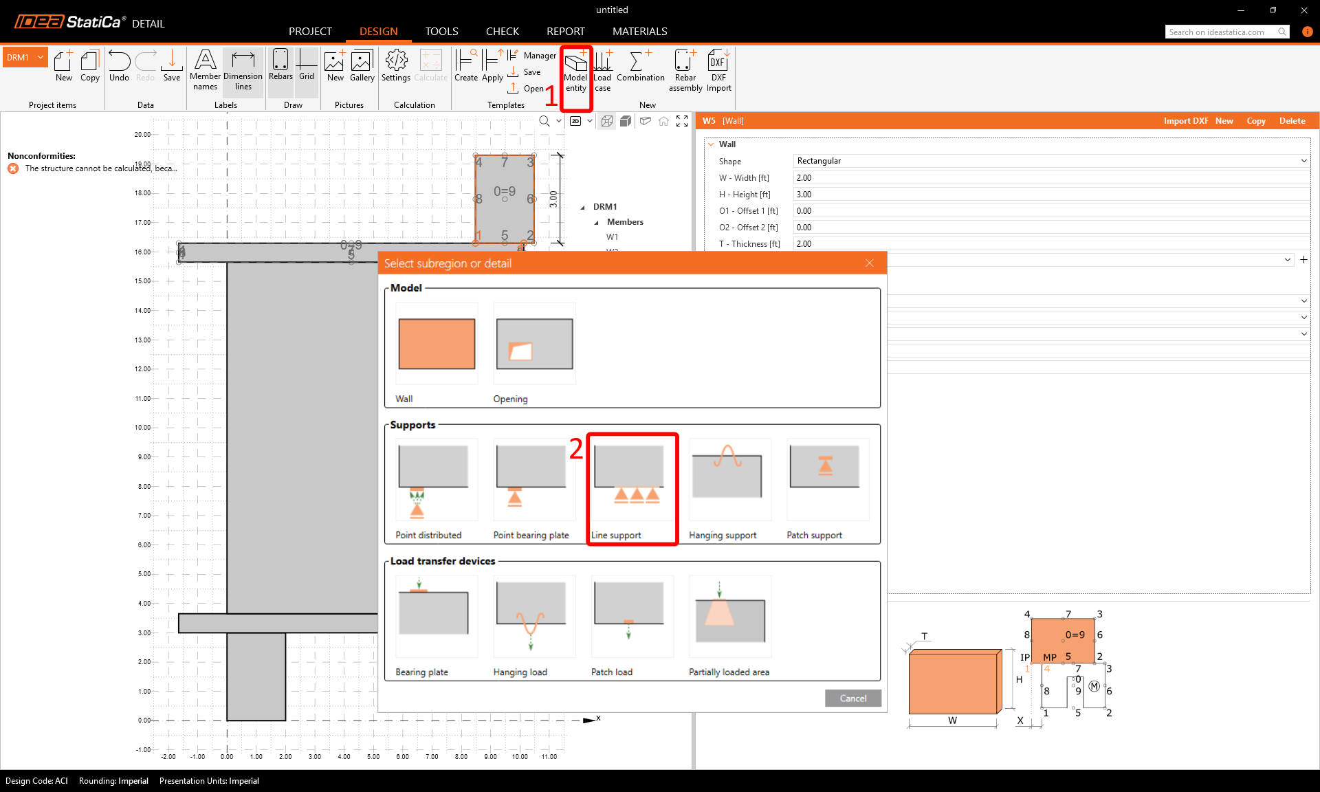
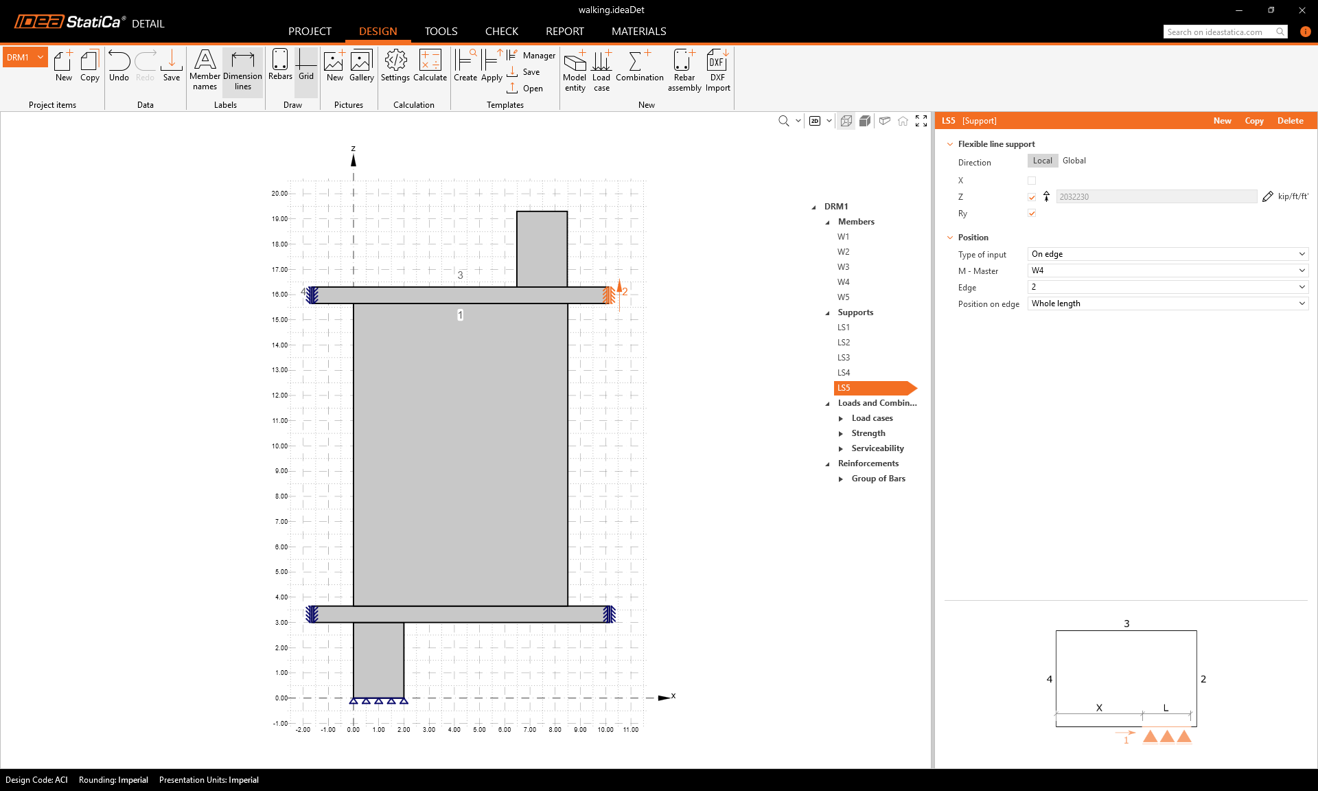
Legen Sie die Parameter wie beim Erstellen der Wände gemäß dem Bild fest und wiederholen Sie den Vorgang für LS2–LS5.


Ihre fertige Geometrie sollte nun wie folgt aussehen:
3 Lasten und Kombinationen
Um eine Last hinzuzufügen, klicken Sie im Menüband auf Lastfall. Ein Lastfall LC1 wird erstellt. Verwenden Sie die Schaltfläche Plus (+), um einen Lastimpuls innerhalb dieses Lastfalls einzufügen – wählen Sie Einzellast und fügen Sie dann einen weiteren Lastimpuls mit Eigengewicht hinzu. Erstellen Sie zwei weitere Lastfälle LC2 und LC3 mit ausschließlich Einzellast-Impulsen.
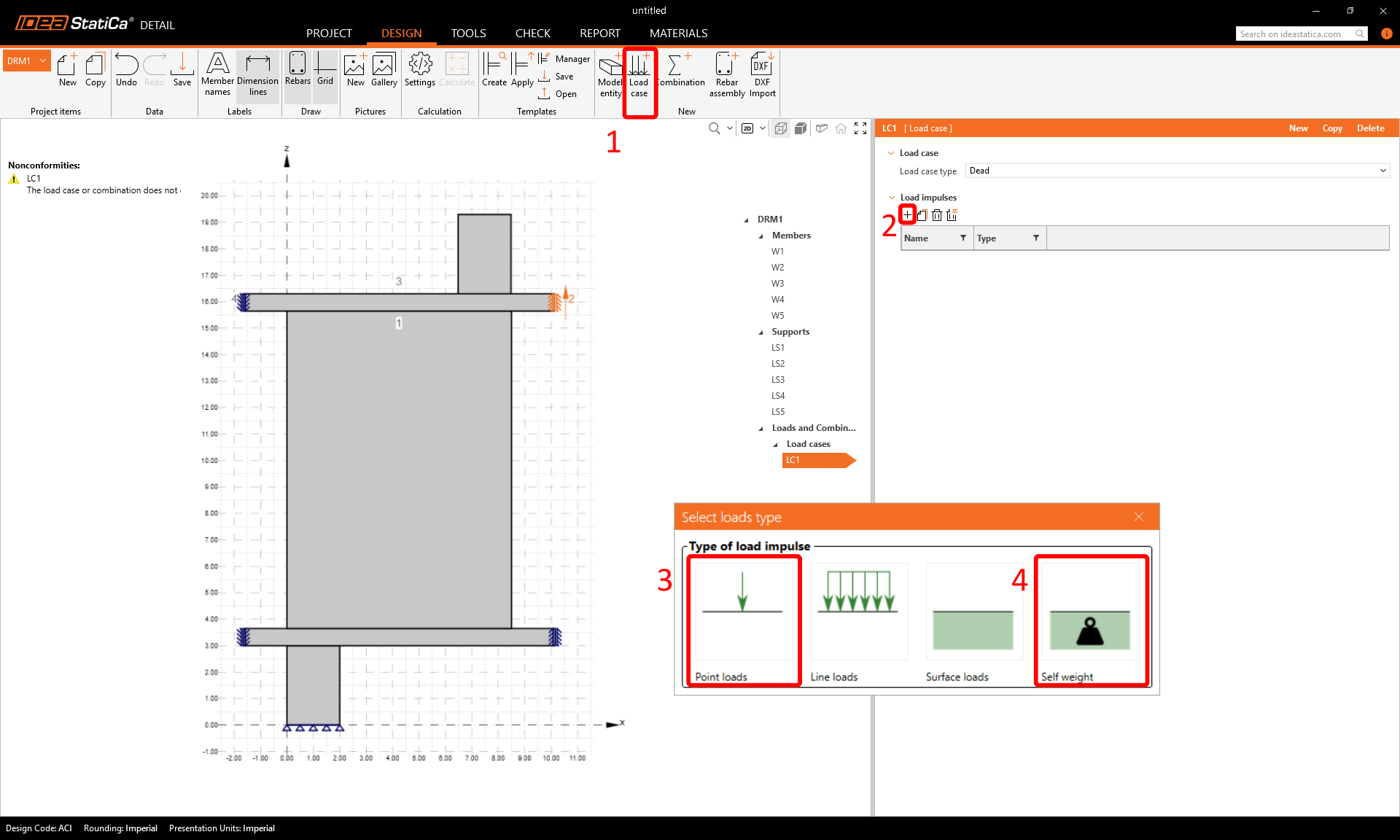
Um zwischen kurzzeitigen und langzeitigen Einwirkungen unterscheiden zu können, weisen Sie die Lastfalltypen Ständig und Veränderlich korrekt zu und geben Sie die Kraftwerte F der Einzellasten sowie die Positionen der Einzelkräfte gemäß den Abbildungen ein.


Lastkombinationen können über den Befehl Kombination im oberen Menüband erstellt werden. Fügen Sie sechs Kombinationen C1–C6 hinzu und klicken Sie dann auf das Bleistiftsymbol, um die Kombinationsbeiwerte zu bearbeiten.
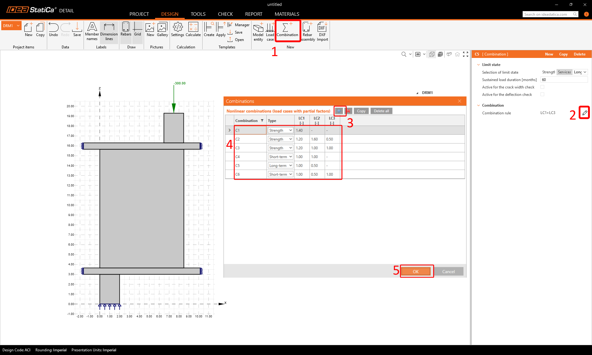
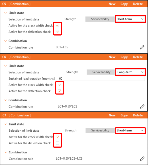
In der Strukturliste sind die Kombinationen in die Gruppen Tragfähigkeit (C1–C3) und Gebrauchstauglichkeit (C4–C6) unterteilt. Um die Nachweise der Rissbreite oder der Durchbiegung zu aktivieren, aktivieren Sie die entsprechenden Kontrollkästchen im Eigenschaftsfenster unter den Gebrauchstauglichkeitskombinationen (C4–C6).
4 Bewehrung
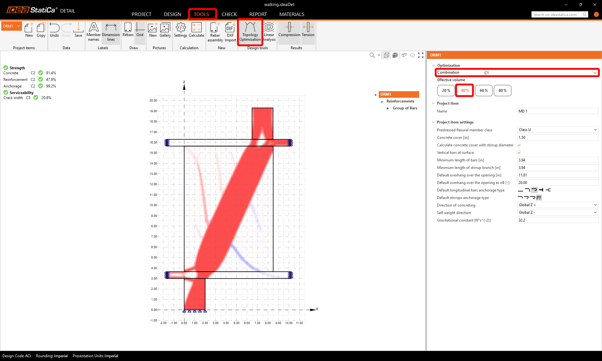
Der nächste Schritt ist die Bewehrung des Modells. Zunächst können wir zur Registerkarte Tools wechseln und die Topologieoptimierung in den Design-Werkzeugen starten, die Ihnen bei der Bemessung der Bewehrung helfen (alternativ können Sie die Lineare Analyse verwenden).
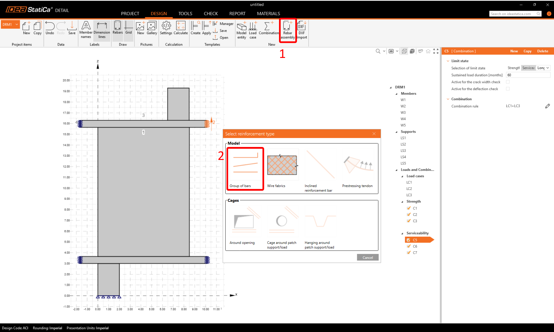
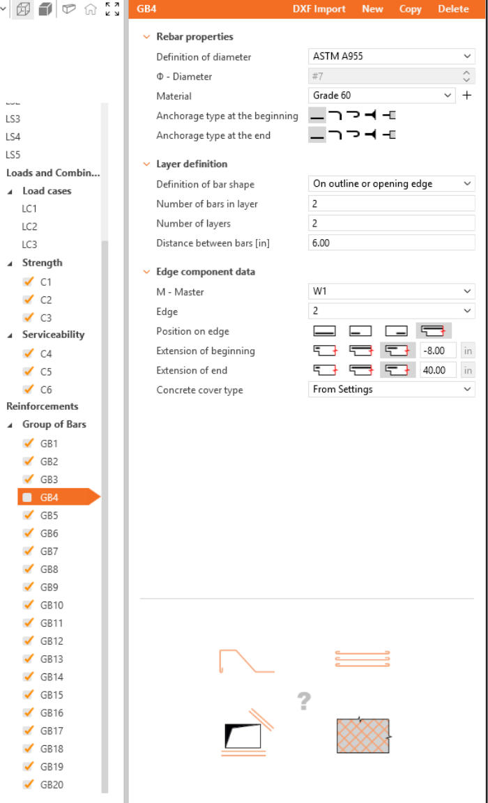
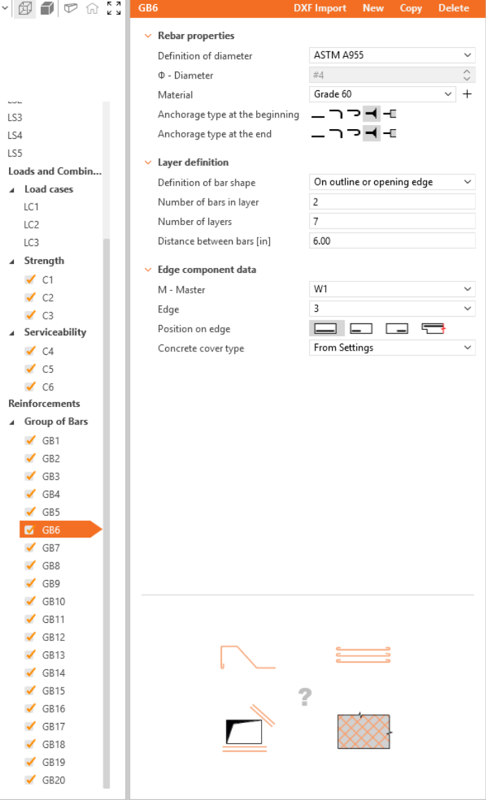
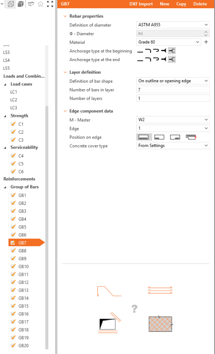
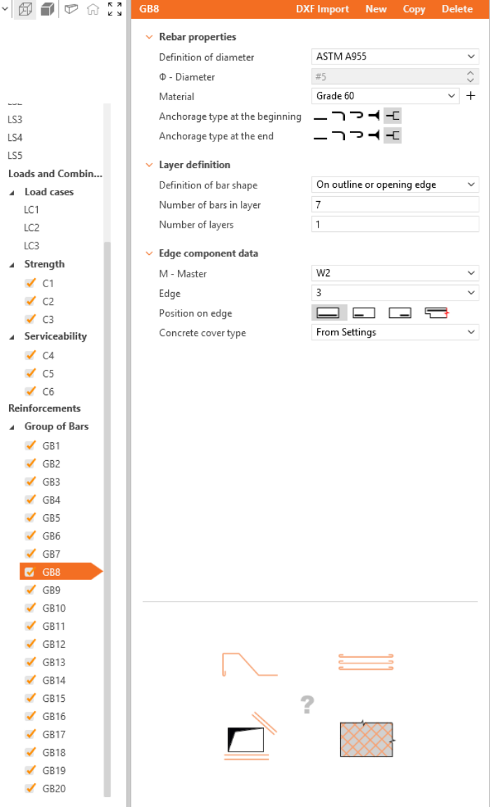
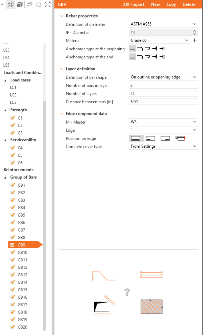
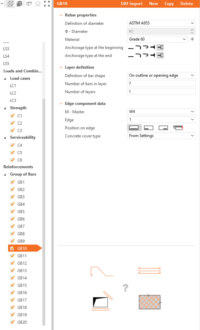
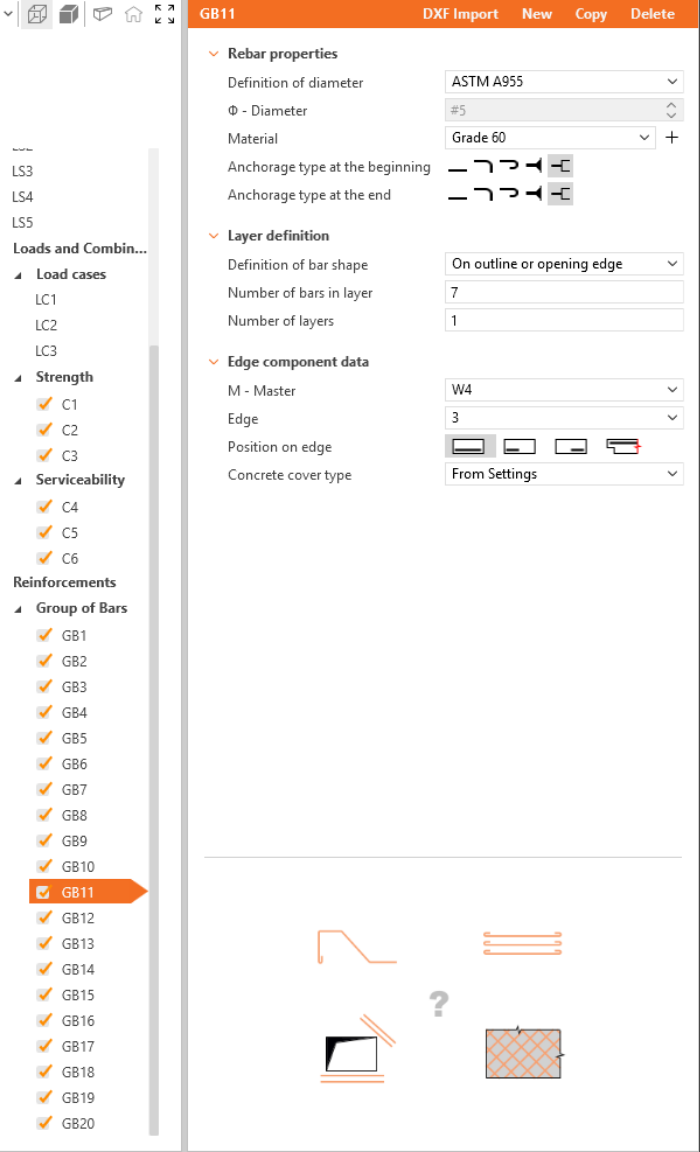
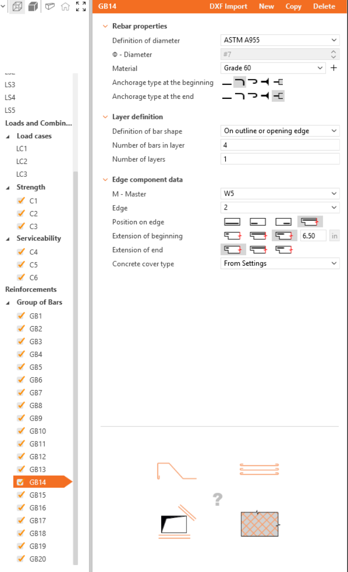
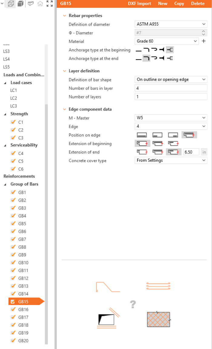
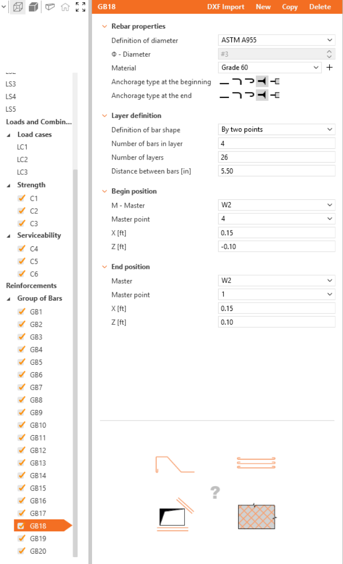
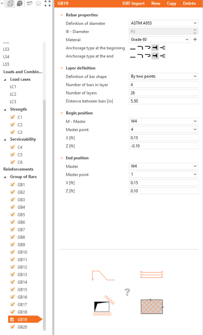
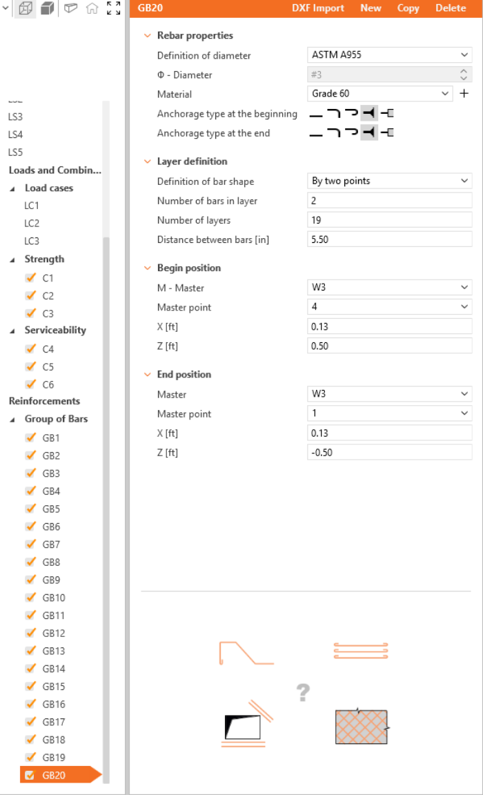
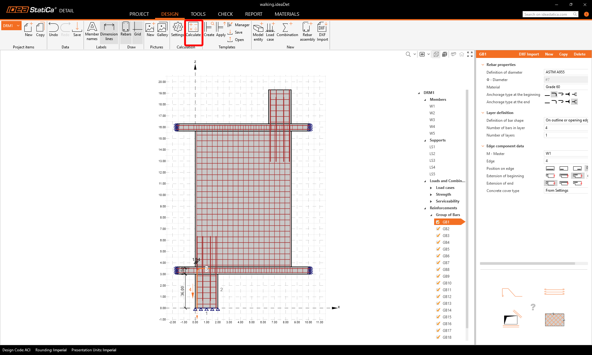
Bemessen Sie nun die Bewehrung. Klicken Sie im Abschnitt Neu auf Bewehrungsgruppe. Wählen Sie den Bewehrungstyp Stabgruppe.
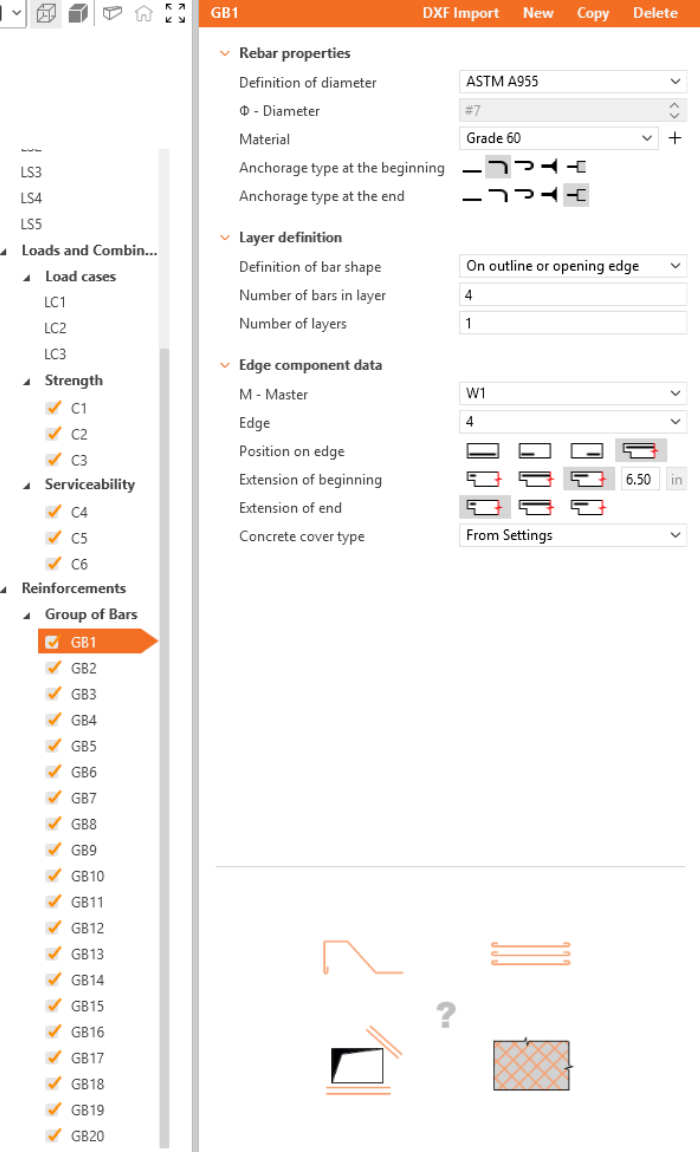
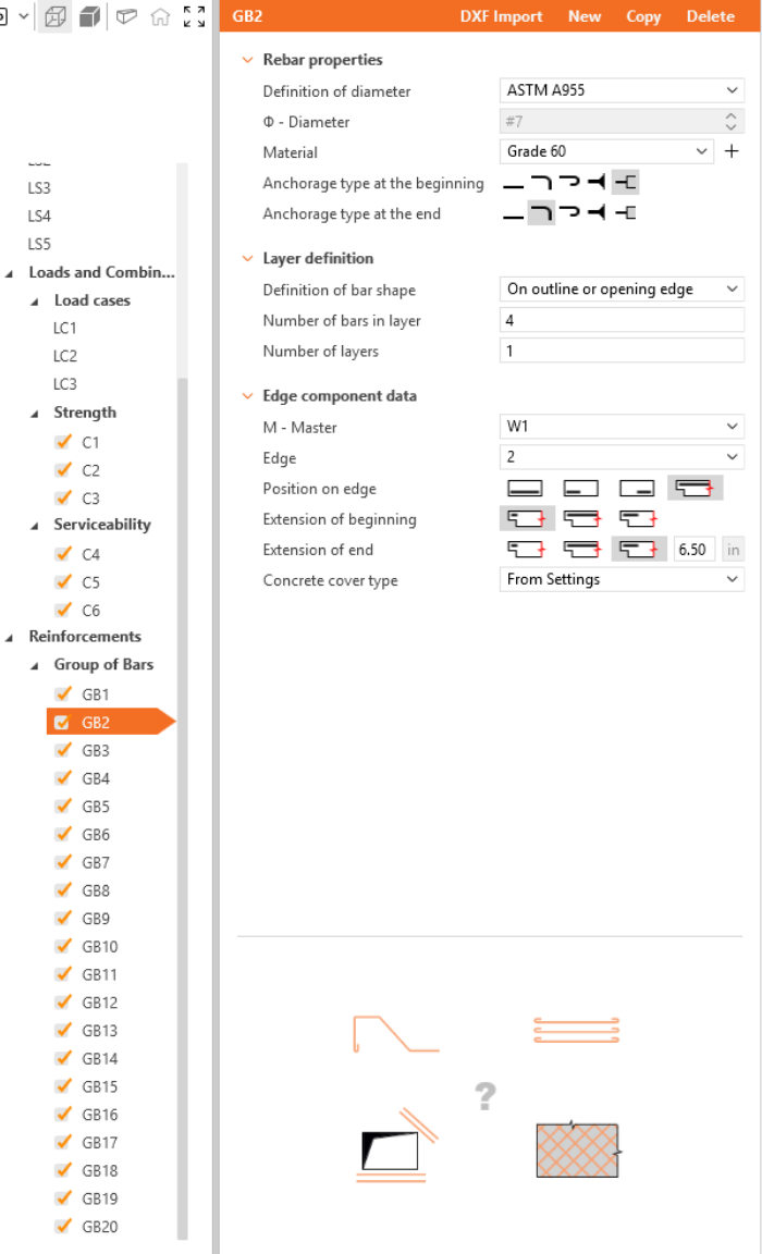
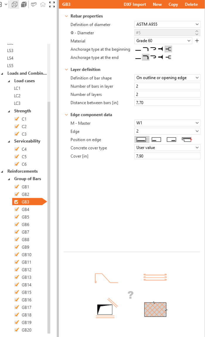
Definieren Sie die Eigenschaften von GB1 und wiederholen Sie den Vorgang für GB2 bis GB20. Sie können auch Kopieren verwenden, um die aktuelle Bewehrung zu kopieren.


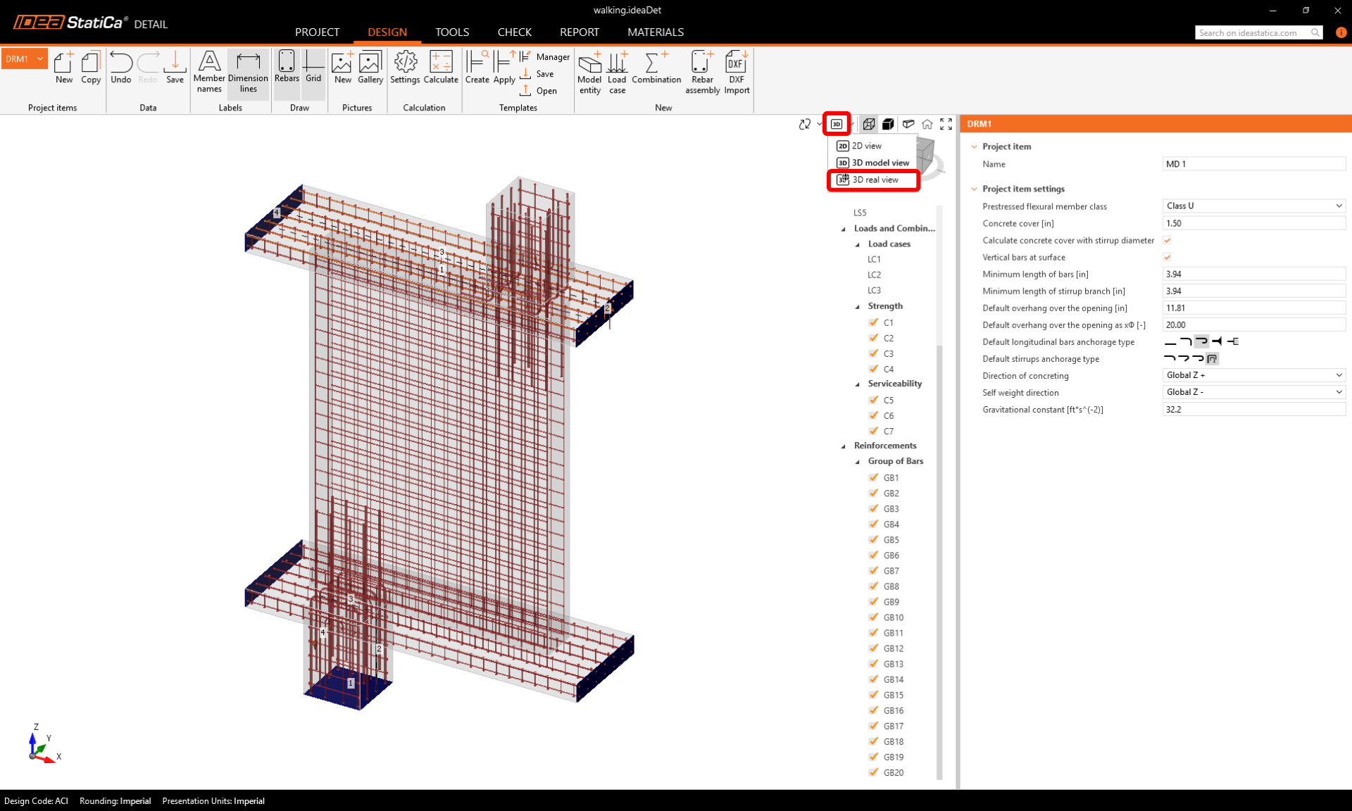
Wechseln Sie zur abschließenden Kontrolle zurück zur Registerkarte Design und wählen Sie die Echte 3D-Ansicht, um die Bewehrungsausrichtung visuell zu überprüfen.
5 Berechnung und Nachweis
Starten Sie die Berechnung, indem Sie im Menüband auf die Schaltfläche Berechnen klicken.
Das Berechnungsmodell wird automatisch generiert. Navigieren Sie zu Nachweis. Auf der linken Seite sehen Sie die Gesamtergebnisse, wie z. B. die Ausnutzung der Materialien.
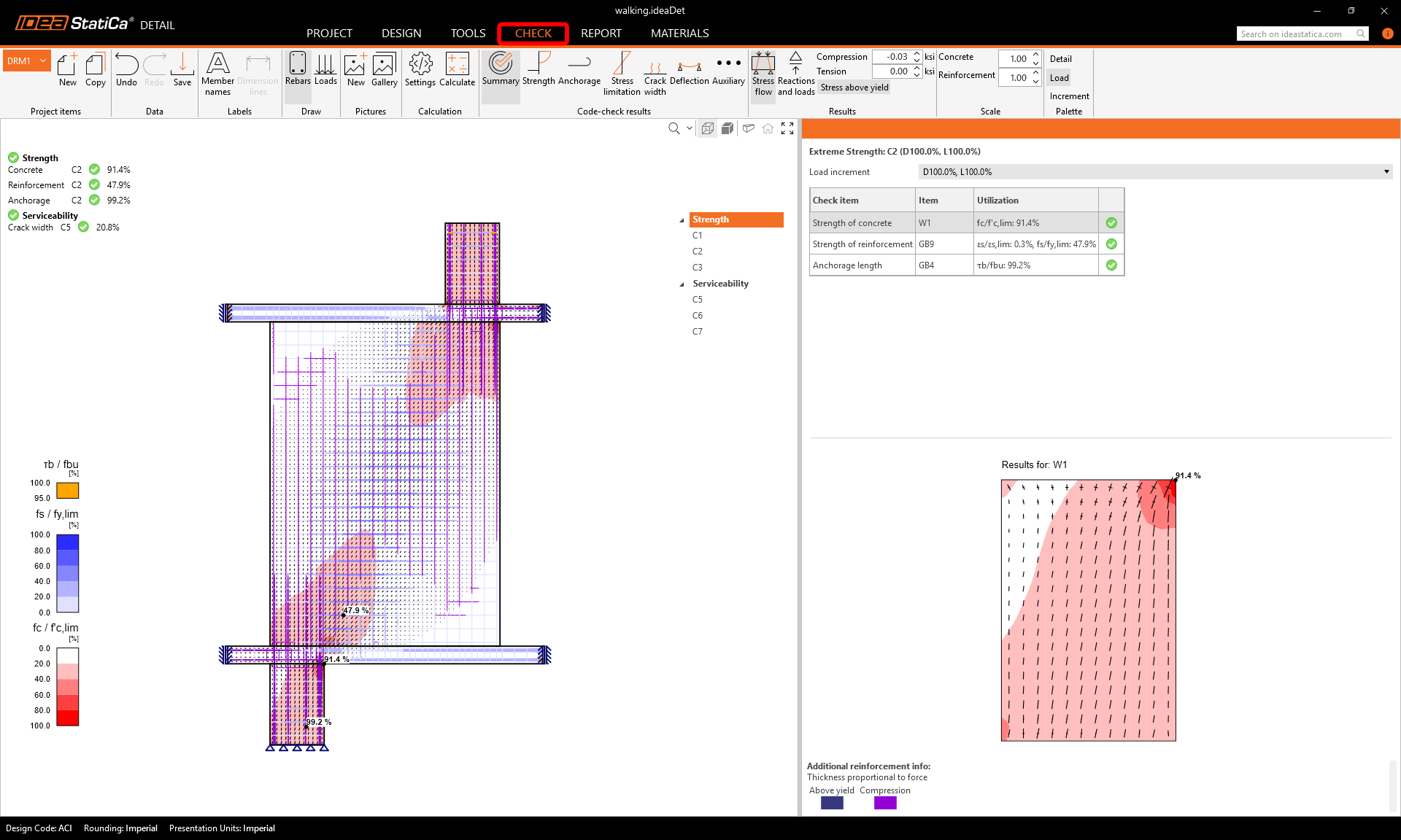
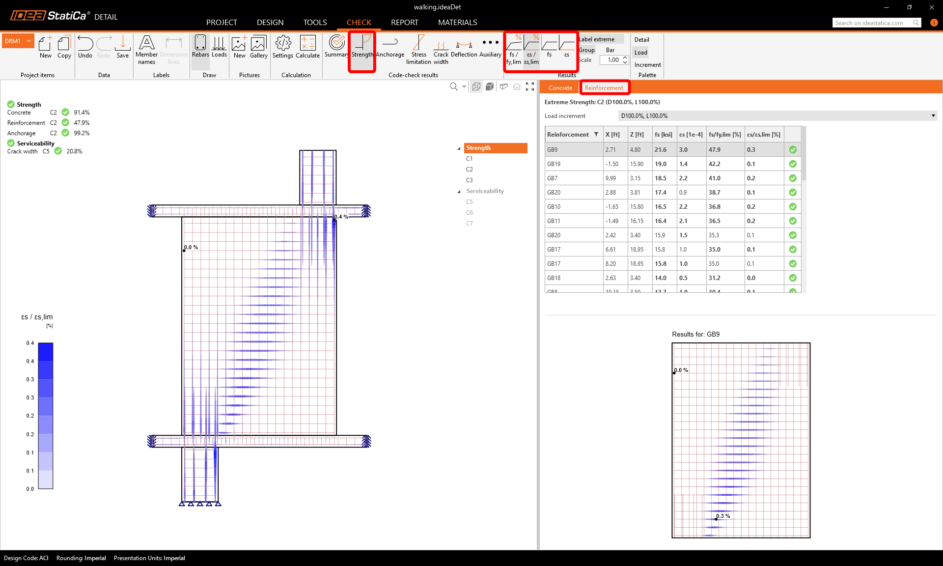
Um die detaillierten Nachweise der einzelnen Komponenten durchzugehen, beginnen Sie mit Tragfähigkeit. Hier werden Betonnachweise angezeigt, wie z. B. die Ausnutzung unter Spannung sowie die Richtung der Hauptspannungen und Hauptdehnungen, die im Menüband eingeblendet werden können. Außerdem können Sie die Richtungen und den Maßstab der Spannungen ändern.
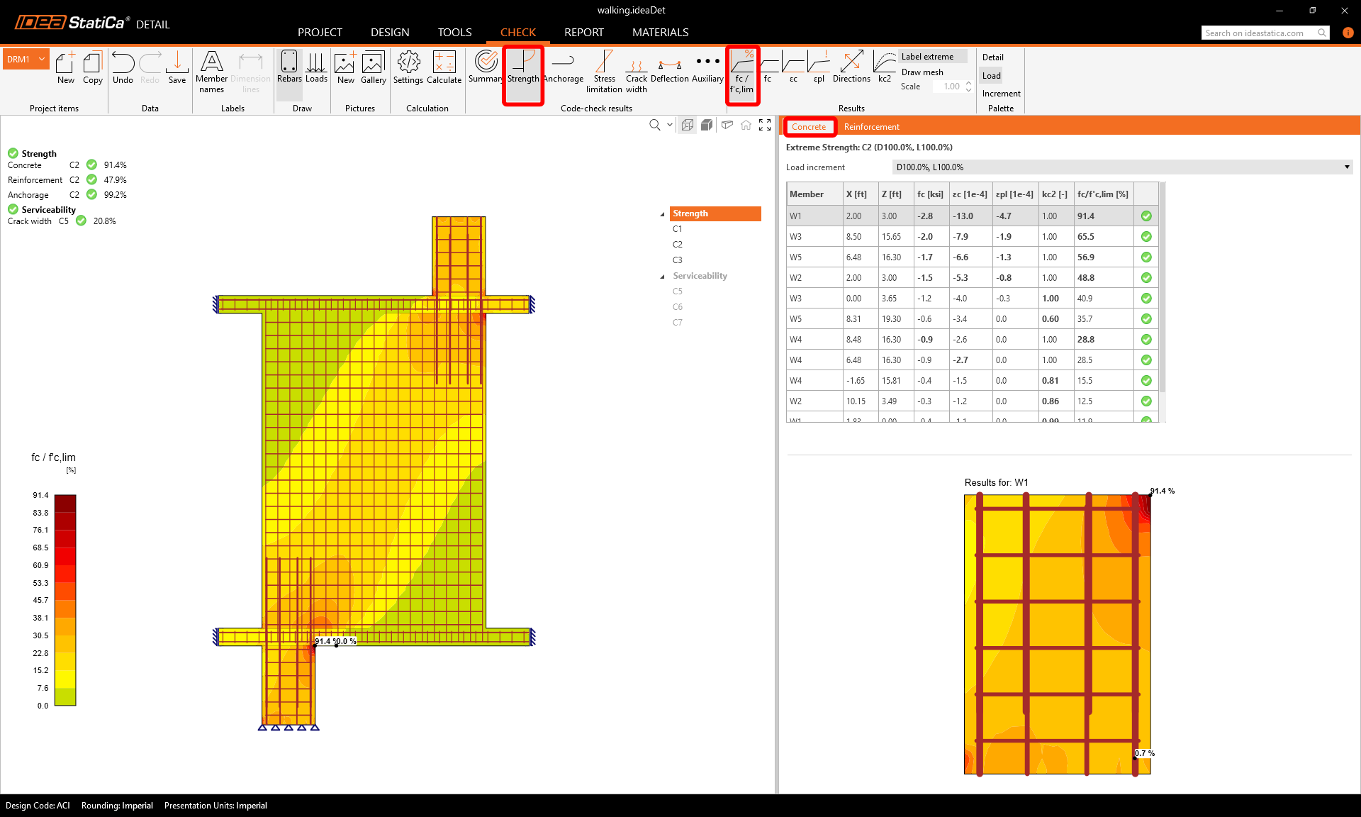
Für detaillierte Bewehrungsergebnisse müssen Sie zur Registerkarte Bewehrung wechseln. Dadurch ändern sich die Symbole im Menüband und die Ergebnistabelle wird aufgeklappt. Sie können Ergebnisse für Dehnungen und Spannungen in jedem Stab sowie deren Ausnutzung anzeigen.
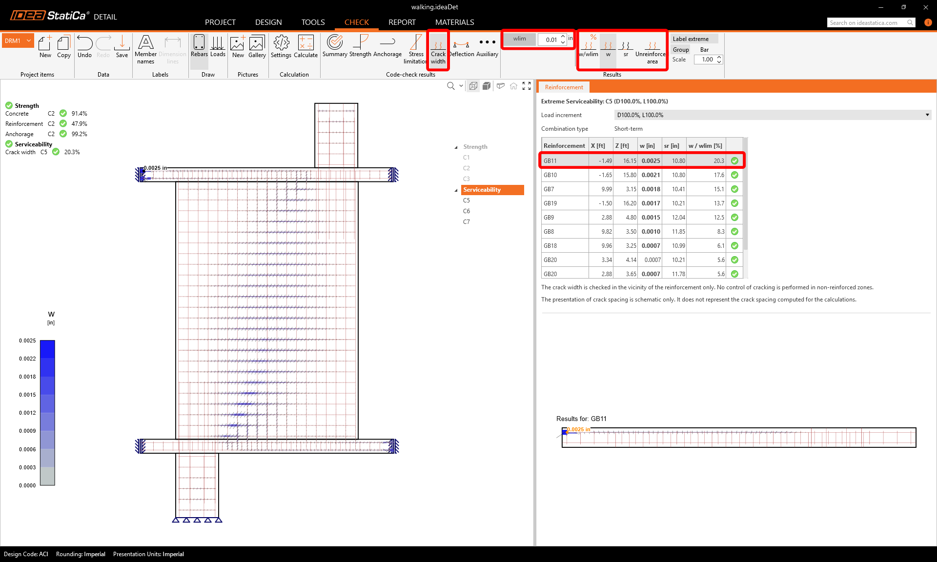
Wechseln wir zum Nachweis der Rissbegrenzung. Neben den Symbolen zum Wechseln zwischen den Ergebnissen gibt es im Menüband Einstellungen zur Festlegung des Grenzwerts.
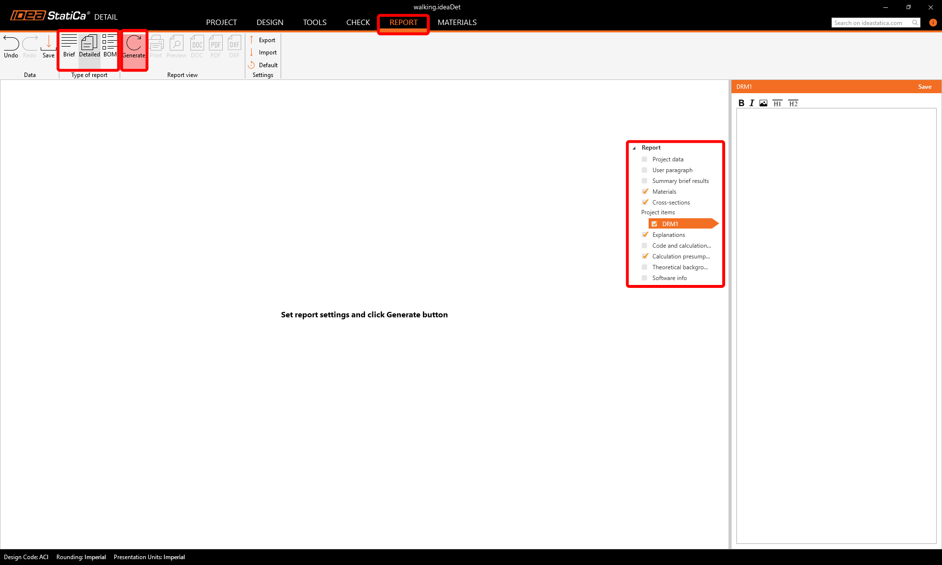
6 Bericht drucken
Jetzt ist es an der Zeit, einen Bericht Ihrer Berechnungen zu drucken. Gehen Sie zur Registerkarte Bericht. Sie können den Berichtstyp Kurz oder Detailliert wählen und den Bericht im Strukturbaum nach Ihren Bedürfnissen weiter anpassen. Wählen Sie die gewünschten Optionen und drücken Sie im oberen Menüband auf Generieren.
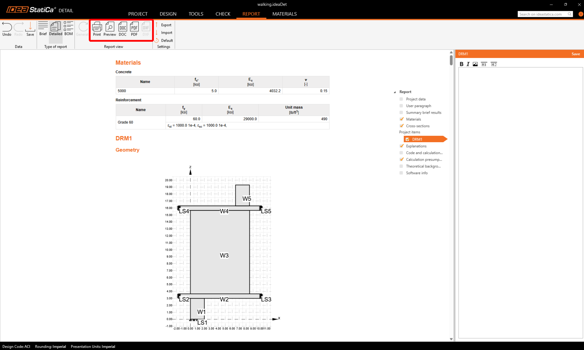
Der Bericht wird generiert und kann als PDF gespeichert oder in eine offene Microsoft Word -Datei exportiert werden.
Sie haben die bewehrte Gehstütze bemessen, optimiert und den Normnachweis geführt.