Módulo de Aprendizagem: Parafusos carregados ao corte (EN)
Introdução
Os parafusos são frequentemente utilizados como fixadores que ligam elementos de aço em ligações de montagem. Facilitam a construção rápida de estruturas de aço. Os empreiteiros exigem tipicamente que todas as ligações em obra sejam aparafusadas; por outras palavras, a soldadura em obra deve ser evitada, apesar de as ligações aparafusadas poderem ser muito mais complexas do que as ligações soldadas e requererem mais material.
O objetivo deste módulo de aprendizagem é familiarizar os estudantes e torná-los confiantes no dimensionamento de ligações aparafusadas simples, através da interação com software de dimensionamento de ligações que fornece feedback visual. Os estudantes devem estar familiarizados com os fundamentos do dimensionamento segundo o Eurocódigo – para mais informações, consulte, por exemplo, as notas de aula ESDEP.
Exemplo: Parafusos ao corte
Calcule a carga nos parafusos e verifique o parafuso mais solicitado.
Geometria
Uma chapa com espessura de 20 mm é ligada a um consolo constituído por duas chapas com espessura de 8 mm cada, por dois parafusos M20 8.8. O consolo é carregado por uma força de 50 kN a uma distância de 100 mm da extremidade da chapa. Os furos dos parafusos são normalizados (\(d_0=22\textrm{ mm}\)) e a força de corte passa pela zona roscada.
Solução
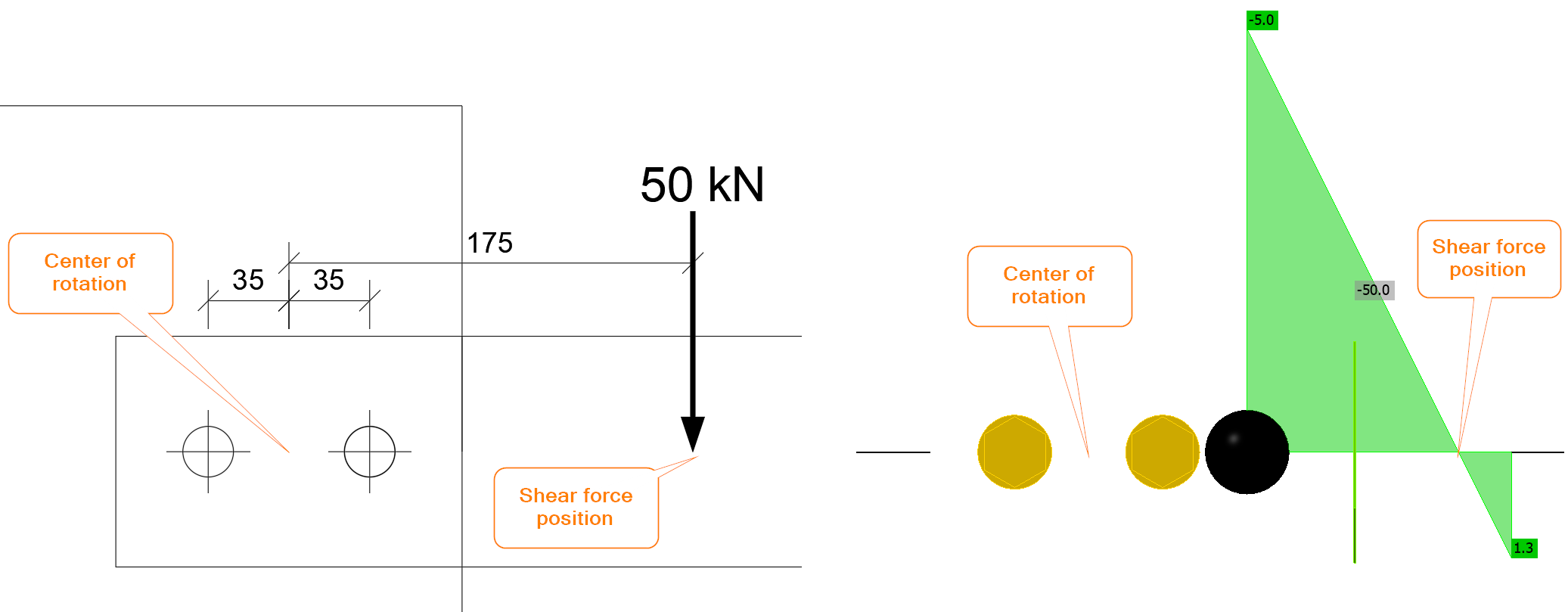
É fundamental determinar o centro de rotação e a carga em cada parafuso. O centro de rotação de um grupo de parafusos carregado ao corte é assumido como estando no centro. A ligação aparafusada é carregada por uma força de corte e um momento fletor. A força de corte é \(V=50\textrm{ kN}\) e o momento fletor é \(M=50\cdot 0.175=8.75 \textrm{kNm}\). No IDEA StatiCa, a posição da força de corte deve ser corretamente definida ou a ligação carregada por uma combinação de força de corte e momento fletor.
A força de corte é transferida pelos parafusos de forma uniforme, ou seja, cada parafuso transfere a mesma parcela da carga de corte:
\[F_{1,V}=V_{Ed}/n_b=50/2=25\textrm{ kN}\]
onde:
- \(V_{Ed}\) – força de corte aplicada
- \(n_b\) – número de parafusos
No IDEA StatiCa, se a posição da força de corte for definida em Parafusos, o grupo de parafusos é carregado exclusivamente ao corte:
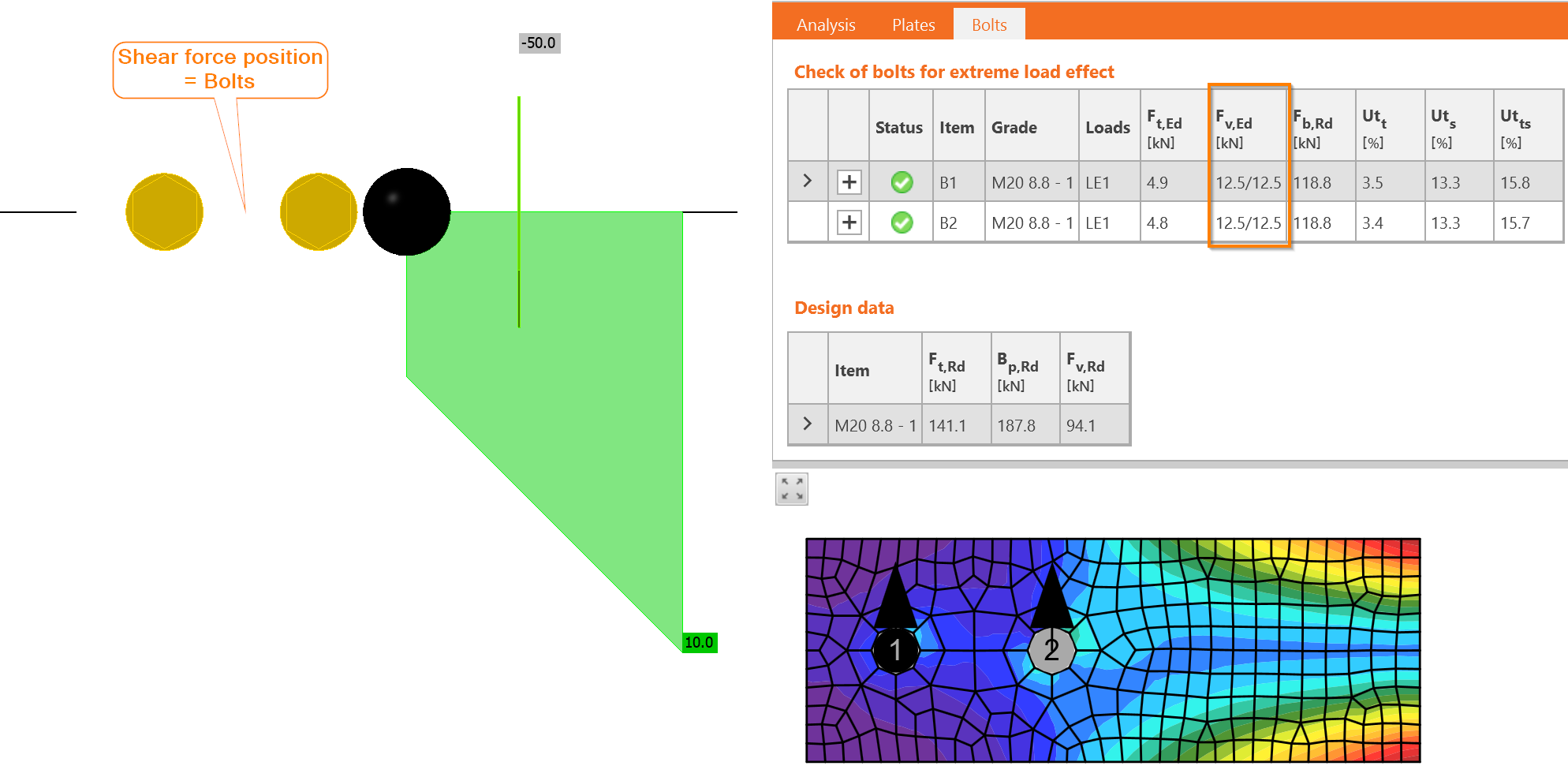
As forças são de facto idênticas e cada parafuso é carregado por 12,5/12,5, ou seja, 12,5 kN em cada plano de corte.
O momento fletor é igualmente transferido pelo grupo de parafusos. Cada parafuso é carregado proporcionalmente à sua distância ao centro de rotação. Neste exemplo, existem apenas dois parafusos com distâncias idênticas:
\[r_i=p/2=70/2=35\textrm{ mm}\]
onde:
- \(r_i\) – distância do parafuso ao centro de rotação
- \(p\) – espaçamento entre parafusos
A força que atua em cada parafuso, \(F_{1,M}\), é calculada:
\[F_{1,M}=M_{Ed}\frac{r_1}{\Sigma r_i^2}=8.75\frac{0.035}{0.035^2+0.035^2}=125\textrm{ kN}\]
onde:
- \(M_{Ed}\) – momento fletor que atua na ligação
- \(r_1\) – distância do parafuso em análise ao centro de rotação
- \(r_i\) – distância de cada parafuso ao centro de rotação
Apesar de o ponto de aplicação da carga ser bastante próximo, apenas a 100 mm da extremidade da chapa, a força no parafuso resultante do momento fletor é muito elevada.
No IDEA StatiCa, a ligação pode ser carregada apenas pelo momento fletor:
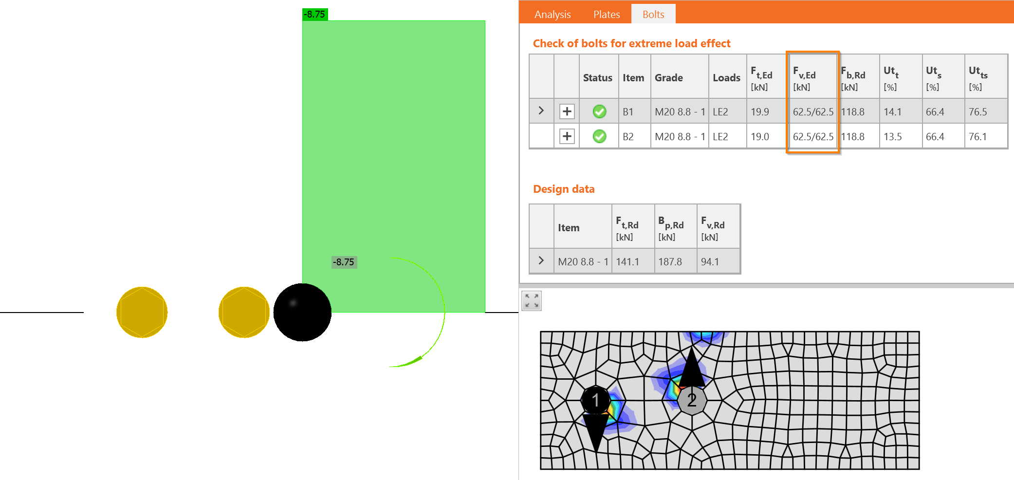
Agora, devemos efetuar a soma vetorial de ambos os efeitos – força de corte e momento fletor. A direção das forças é aqui determinante. As forças nos parafusos devidas à força de corte \(V_{Ed}\) atuam para baixo, enquanto as forças devidas ao momento fletor rodam em torno do centro de rotação. Isso significa que uma atua para cima e a outra para baixo. A força num parafuso é subtraída: \(F_{1,v,Ed} = 25 - 125 = - 100\textrm{ kN}\), e a força no outro parafuso é somada: \(F_{2,v,Ed} = 25 + 125 = 150\textrm{ kN}\).
As forças de corte no IDEA StatiCa são exatamente as mesmas.
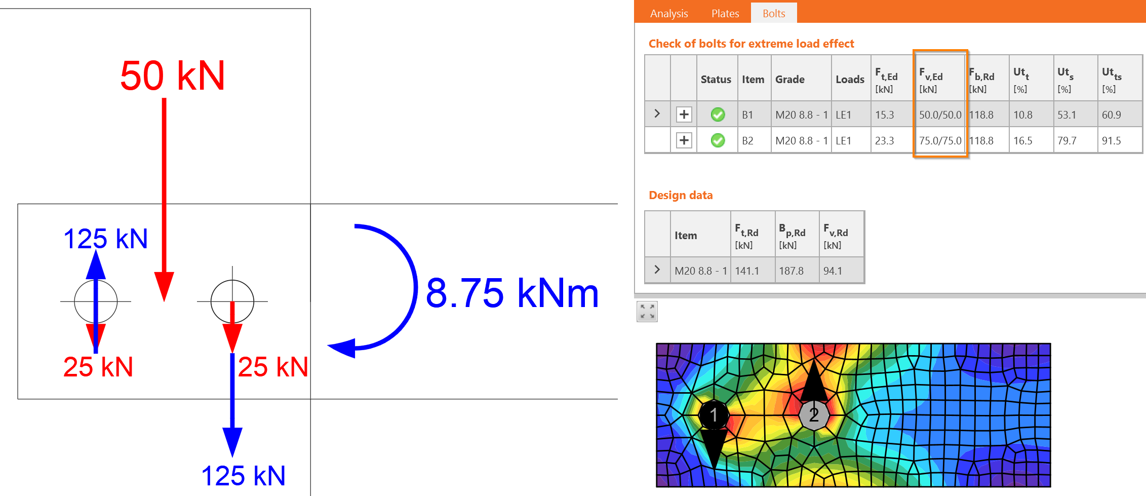
A força maior determina o dimensionamento, \(F_{v,Ed}=F_{2,v,Ed}=150\textrm{ kN}\).
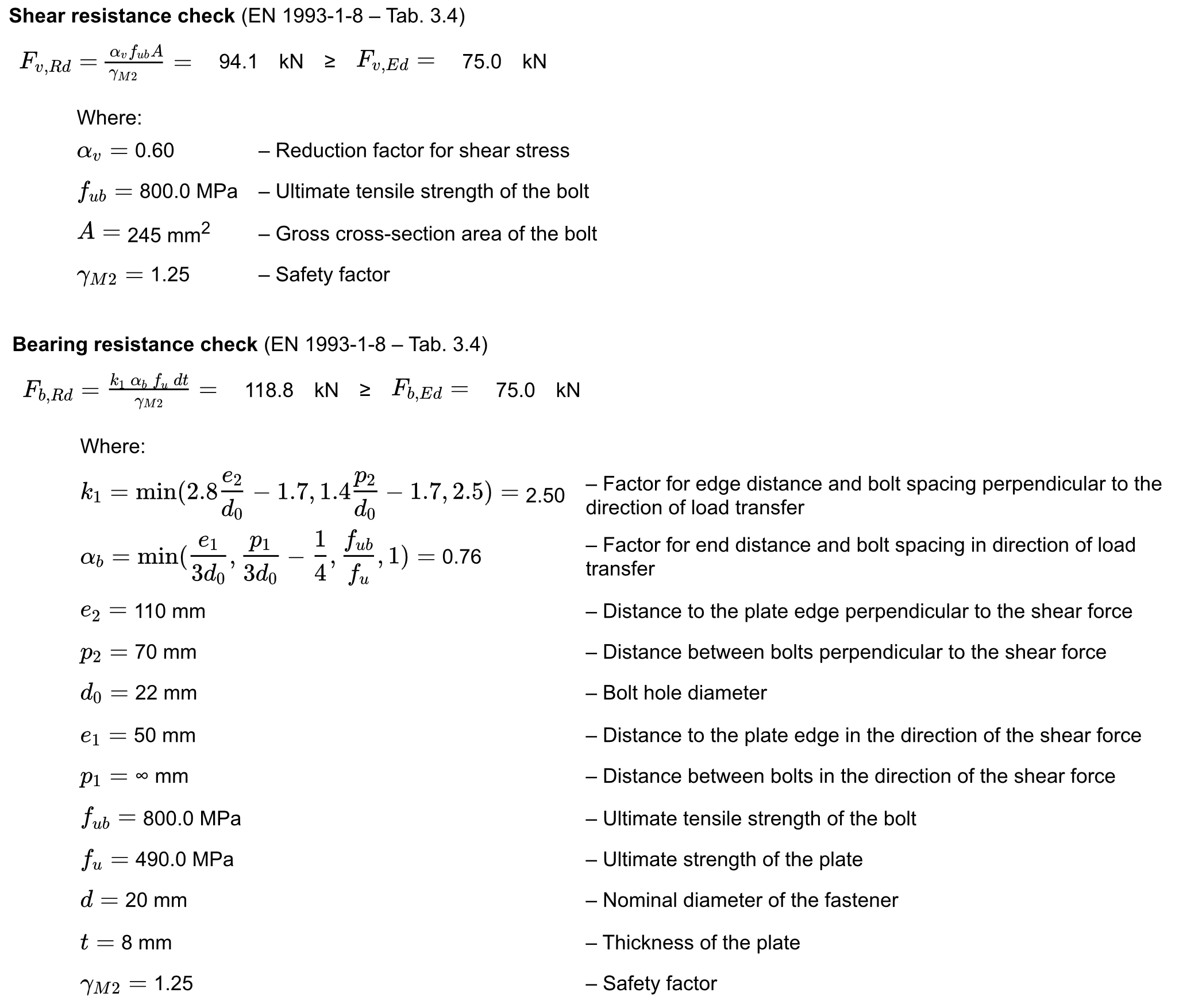
As verificações detalhadas são apresentadas para o parafuso B2. Os parafusos carregados ao corte devem ser verificados quanto a:
- Resistência ao corte
- Resistência ao esmagamento
Laboratório Virtual – Parafusos ao Corte
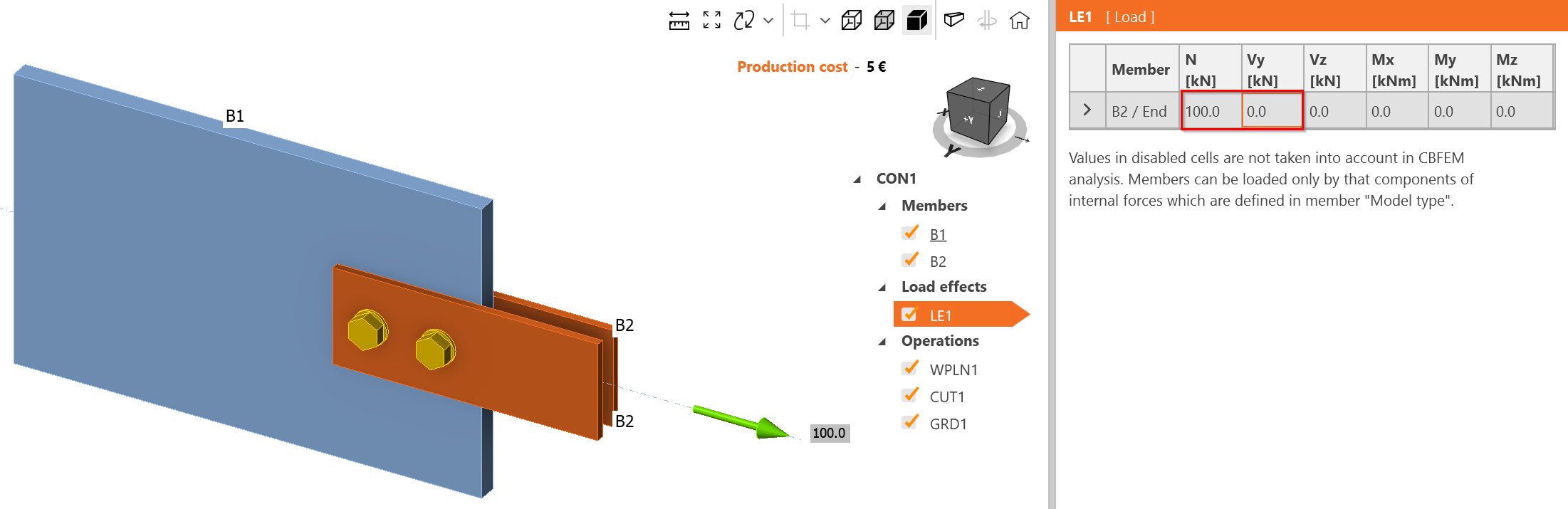
Altere o efeito da ação para carga de tração apenas, 100 kN.
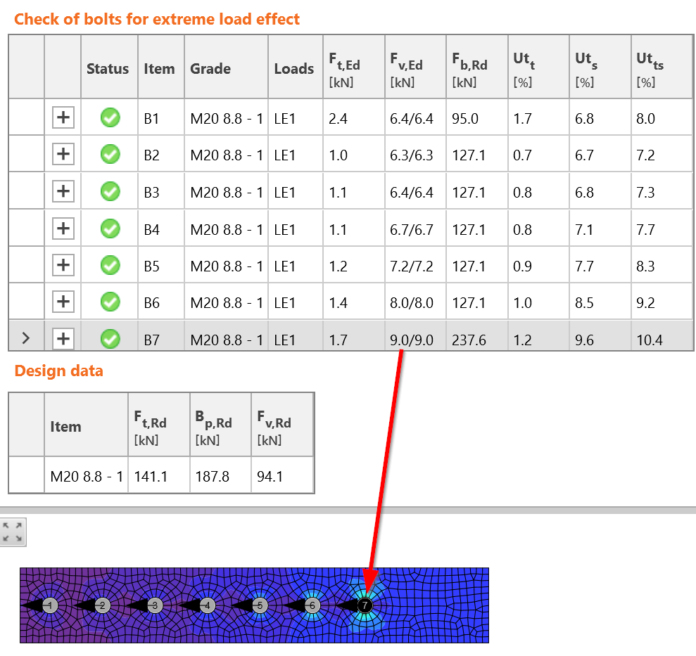
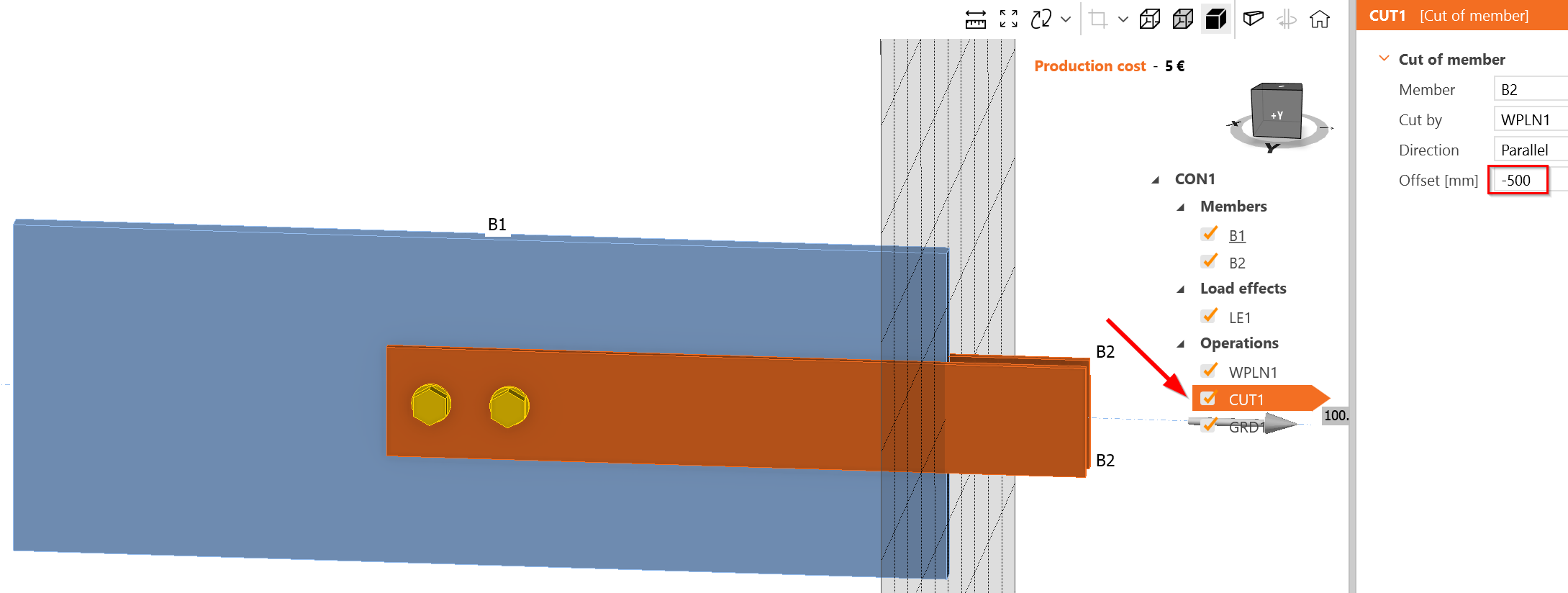
Crie uma ligação aparafusada longa. Uma ligação aparafusada longa tem comprimento superior a \(15\cdot d = 15\cdot 20 = 300\textrm{ mm}\). Aumente a sobreposição dos elementos:
Adicione mais parafusos com um espaçamento de 70 mm:
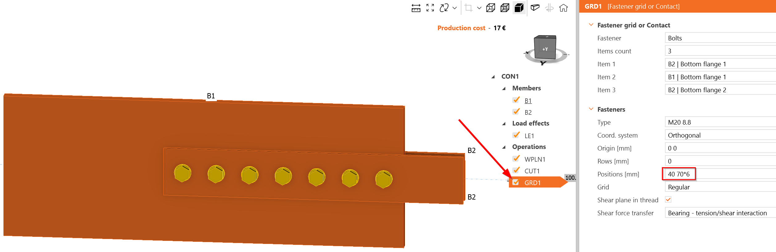
O parafuso mais carregado é o B7, que está de facto localizado no início do grupo de parafusos. A carga que atua em cada plano de corte é de 9 kN, ou seja, 18 kN no parafuso B7. Este valor é superior aos 14,72 kN estimados. Parece que o IDEA StatiCa fornece uma distribuição de forças nos parafusos mais conservadora; no entanto, pode variar com o carregamento consecutivo devido ao cálculo não linear e ao diagrama não linear força-deformação do parafuso ao corte.