Modul de Învățare: Șuruburi solicitate la forfecare (EN)
Introducere
Șuruburile sunt utilizate în mod obișnuit ca dispozitive de fixare pentru conectarea elementelor din oțel în îmbinările de asamblare. Acestea facilitează construcția rapidă a structurilor metalice. Antreprenorii solicită de obicei ca toate îmbinările de pe șantier să fie șurubuite; cu alte cuvinte, sudarea pe șantier ar trebui evitată, în ciuda faptului că îmbinările șurubuite pot fi mult mai complicate decât îmbinările sudate și necesită mai mult material.
Scopul acestui modul de învățare este de a familiariza studenții și de a le oferi încredere în proiectarea îmbinărilor simple cu șuruburi prin interacțiunea cu software-ul de proiectare a îmbinărilor, care oferă feedback vizual. Studenții ar trebui să fie familiarizați cu noțiunile de bază ale proiectării conform Eurocodului – pentru mai multe informații, consultați, de exemplu, notele de curs ESDEP.
Exemplu: Șuruburi la forfecare
Calculați încărcarea pe șuruburi și verificați șurubul cel mai solicitat.
Geometrie
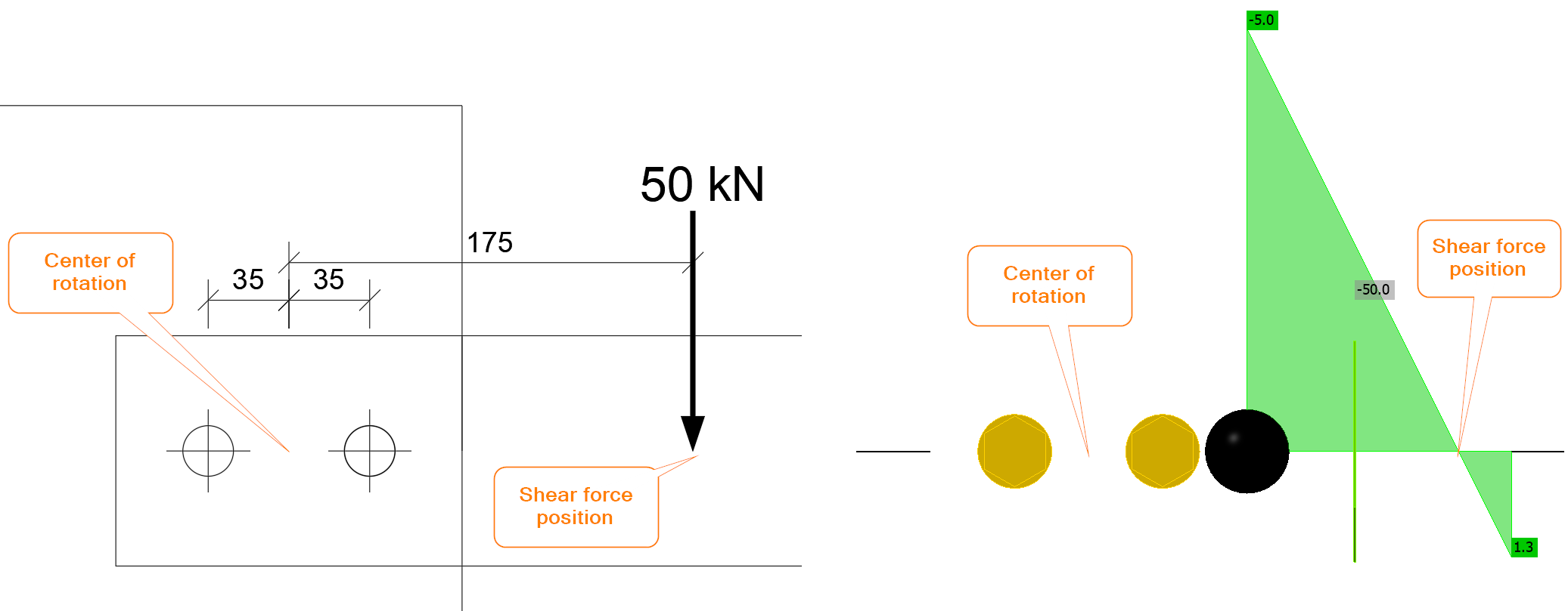
O placă cu grosimea de 20 mm este conectată la o consolă formată din două plăci cu grosimea de 8 mm fiecare, prin două șuruburi M20 8.8. Consola este încărcată cu o forță de 50 kN la o distanță de 100 mm față de marginea plăcii. Găurile pentru șuruburi sunt standard (\(d_0=22\textrm{ mm}\)), iar forța de forfecare trece prin filet.
Soluție
Esențială este determinarea centrului de rotație și a încărcării pe fiecare șurub. Se presupune că centrul de rotație pentru un grup de șuruburi solicitat la forfecare se află în centrul grupului. Îmbinarea cu șuruburi este solicitată de o forță tăietoare și un moment încovoietor. Forța tăietoare este \(V=50\textrm{ kN}\), iar momentul încovoietor este \(M=50\cdot 0.175=8.75 \textrm{kNm}\). În IDEA StatiCa, poziția forței tăietoare trebuie setată corect sau îmbinarea trebuie încărcată cu o combinație de forță tăietoare și moment încovoietor.
Forța tăietoare este transferată prin șuruburi în mod uniform, adică fiecare șurub preia aceeași parte din încărcarea de forfecare:
\[F_{1,V}=V_{Ed}/n_b=50/2=25\textrm{ kN}\]
unde:
- \(V_{Ed}\) – forța tăietoare de calcul
- \(n_b\) – numărul de șuruburi
În IDEA StatiCa, dacă poziția forței tăietoare este setată la Șuruburi, grupul de șuruburi este solicitat exclusiv la forfecare:
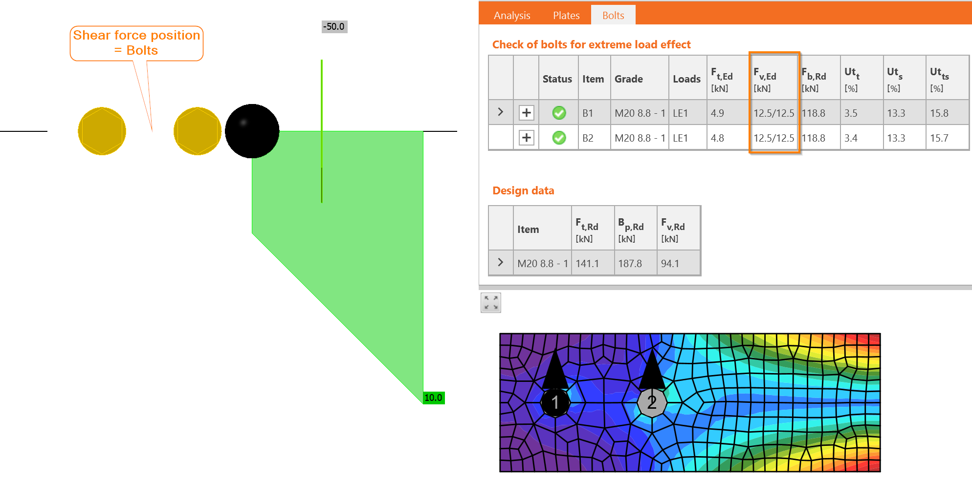
Forțele sunt într-adevăr identice și fiecare șurub este solicitat cu 12,5/12,5, adică 12,5 kN în fiecare plan de forfecare.
Momentul încovoietor este transferat de asemenea prin grupul de șuruburi. Fiecare șurub este solicitat proporțional cu distanța față de centrul de rotație. În acest exemplu, există doar două șuruburi cu distanțe identice:
\[r_i=p/2=70/2=35\textrm{ mm}\]
unde:
- \(r_i\) – distanța de la șurub la centrul de rotație
- \(p\) – distanța dintre șuruburi
Forța care acționează asupra fiecărui șurub, \(F_{1,M}\), se calculează:
\[F_{1,M}=M_{Ed}\frac{r_1}{\Sigma r_i^2}=8.75\frac{0.035}{0.035^2+0.035^2}=125\textrm{ kN}\]
unde:
- \(M_{Ed}\) – momentul încovoietor care acționează asupra îmbinării
- \(r_1\) – distanța de la șurubul analizat la centrul de rotație
- \(r_i\) – distanța de la fiecare șurub la centrul de rotație
Deși punctul de aplicare al încărcării este destul de aproape, la doar 100 mm de marginea plăcii, forța în șurub rezultată din momentul încovoietor este foarte mare.
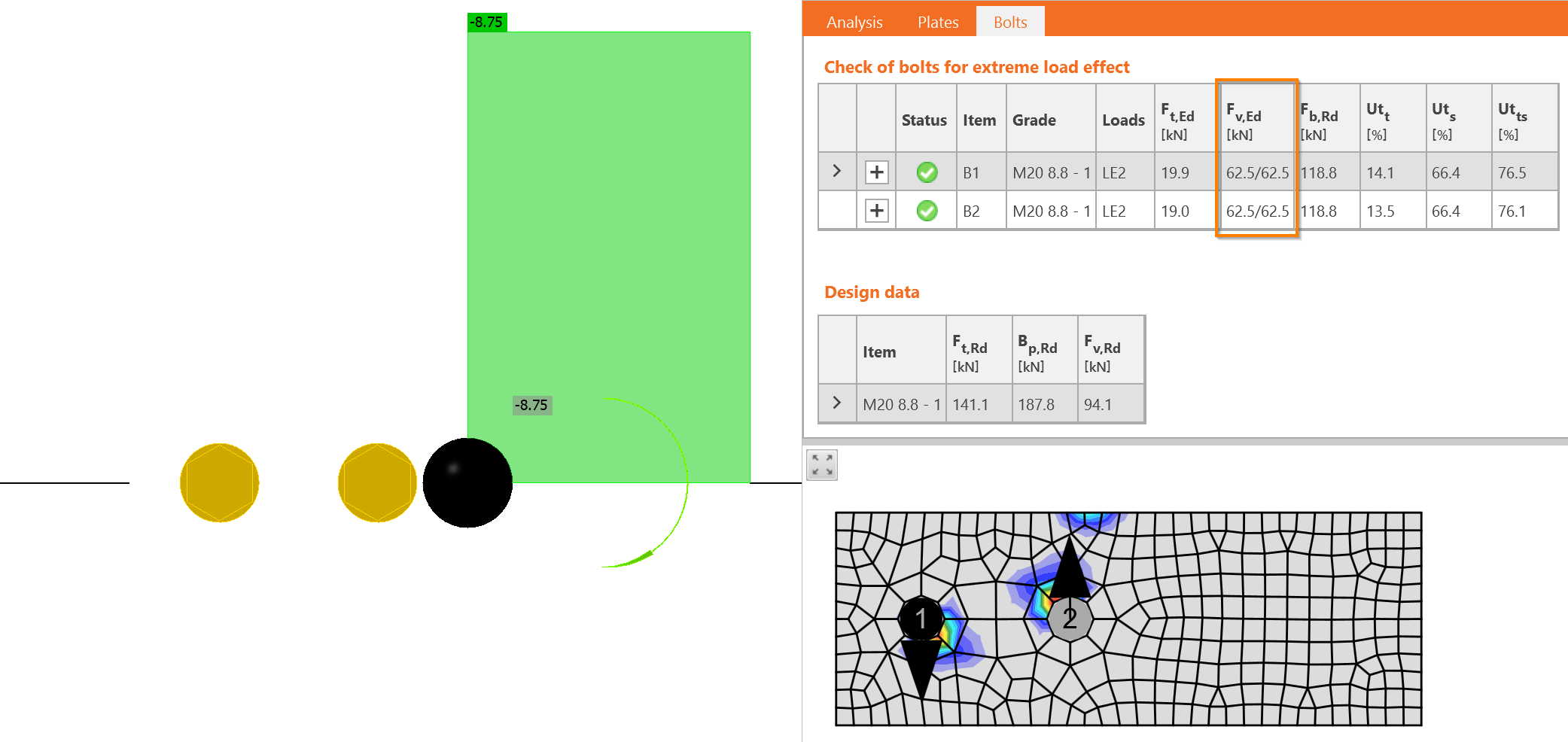
În IDEA StatiCa, îmbinarea poate fi încărcată doar cu moment încovoietor:
Acum, trebuie să efectuăm suma vectorială a ambelor efecte – forța tăietoare și momentul încovoietor. Direcția forțelor este esențială aici. Forțele în șuruburi din forța tăietoare \(V_{Ed}\) acționează în jos, în timp ce forțele din momentul încovoietor se rotesc în jurul centrului de rotație. Aceasta înseamnă că una acționează în sus și cealaltă în jos. Forța într-un șurub se scade: \(F_{1,v,Ed} = 25 - 125 = - 100\textrm{ kN}\), iar forța în celălalt șurub se adună: \(F_{2,v,Ed} = 25 + 125 = 150\textrm{ kN}\).
Exact aceleași forțe tăietoare se obțin în IDEA StatiCa.
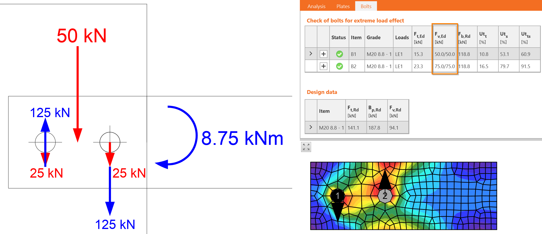
Forța mai mare determină proiectarea, \(F_{v,Ed}=F_{2,v,Ed}=150\textrm{ kN}\).
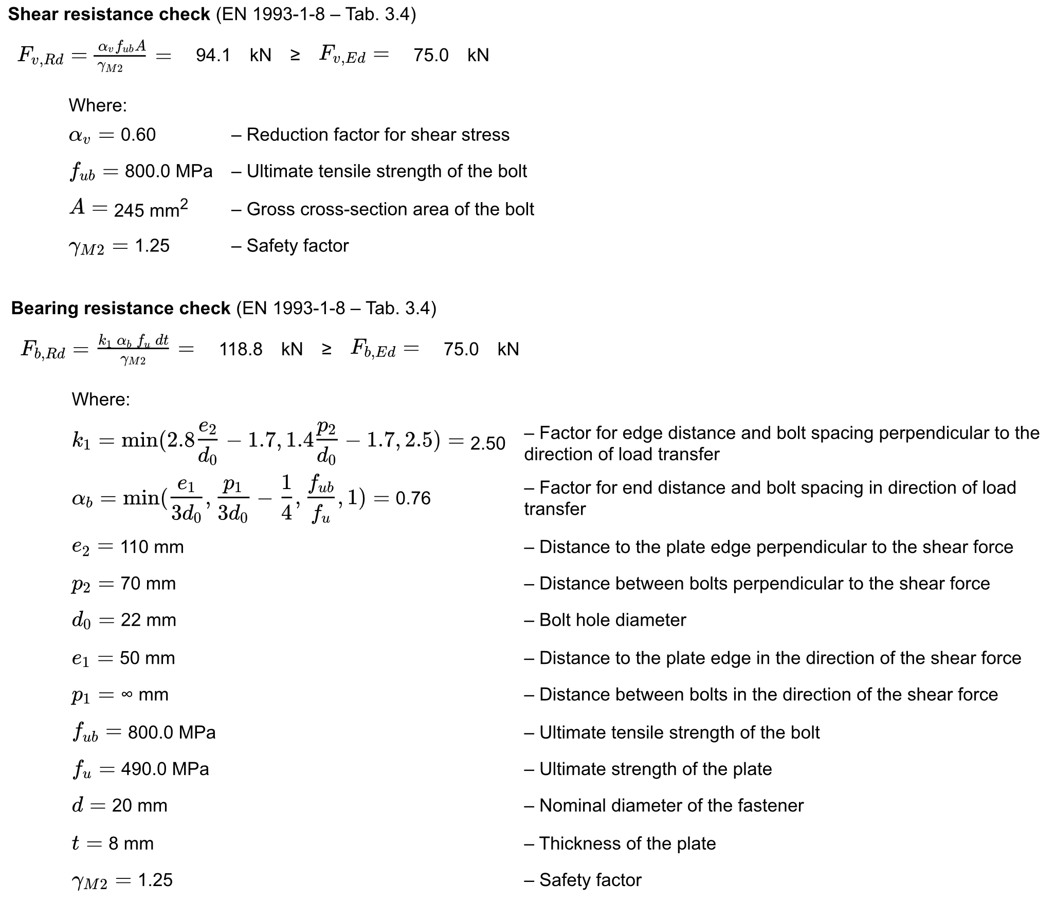
Verificările detaliate sunt furnizate pentru șurubul B2. Șuruburile solicitate la forfecare trebuie verificate pentru:
- Rezistența la forfecare
- Rezistența la presiune pe gaură
Laborator Virtual – Șuruburi la Forfecare
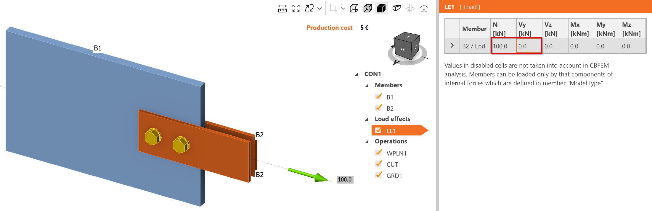
Modificați efectul de încărcare la încărcare axială de întindere, 100 kN.
Creați o îmbinare cu șuruburi de lungime mare. O îmbinare cu șuruburi de lungime mare este mai lungă de \(15\cdot d = 15\cdot 20 = 300\textrm{ mm}\). Extindeți suprapunerea elementelor:
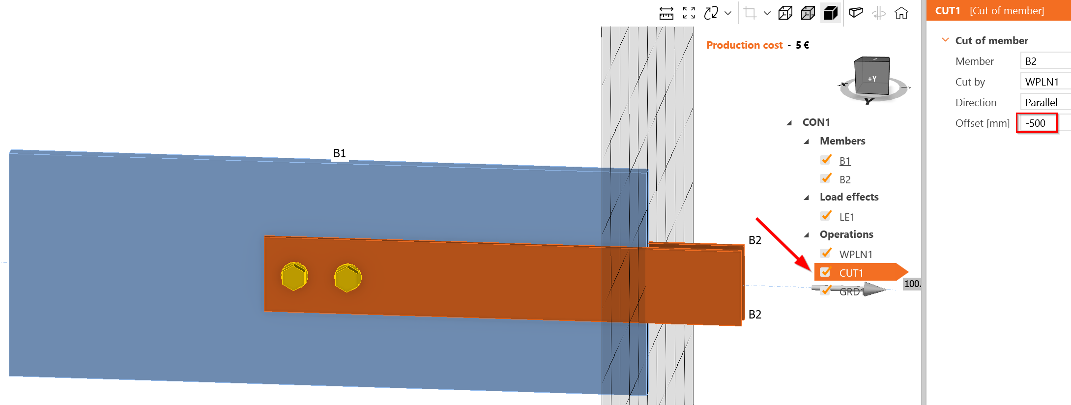
Adăugați mai multe șuruburi cu un pas de 70 mm:
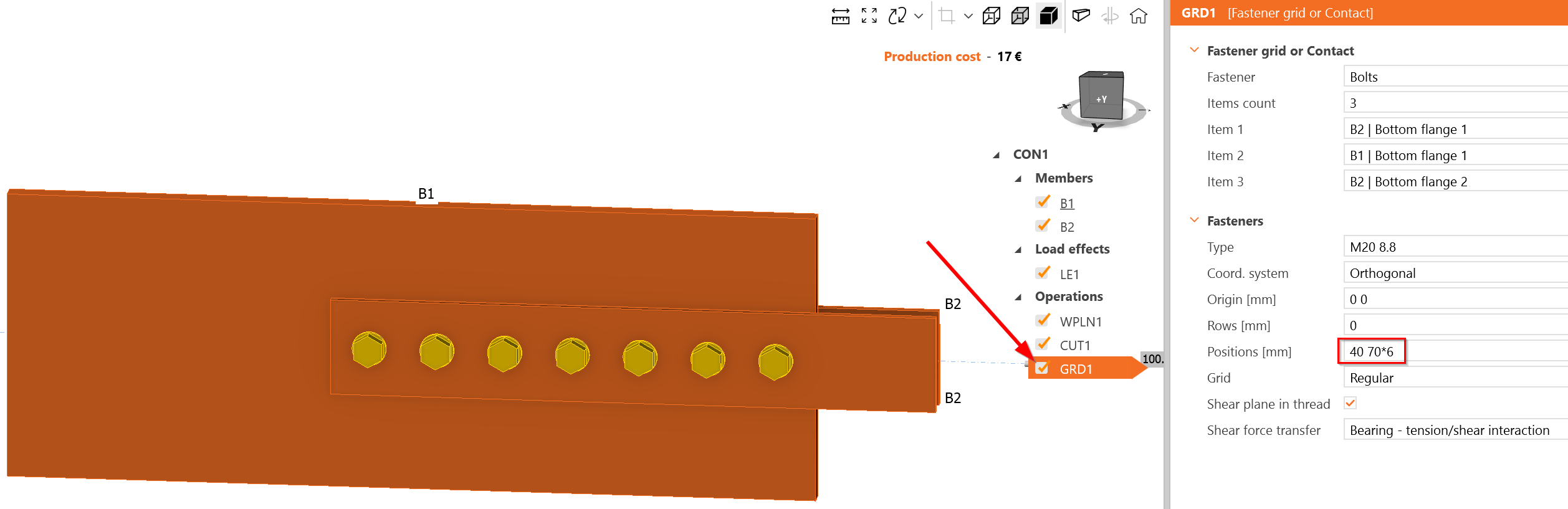
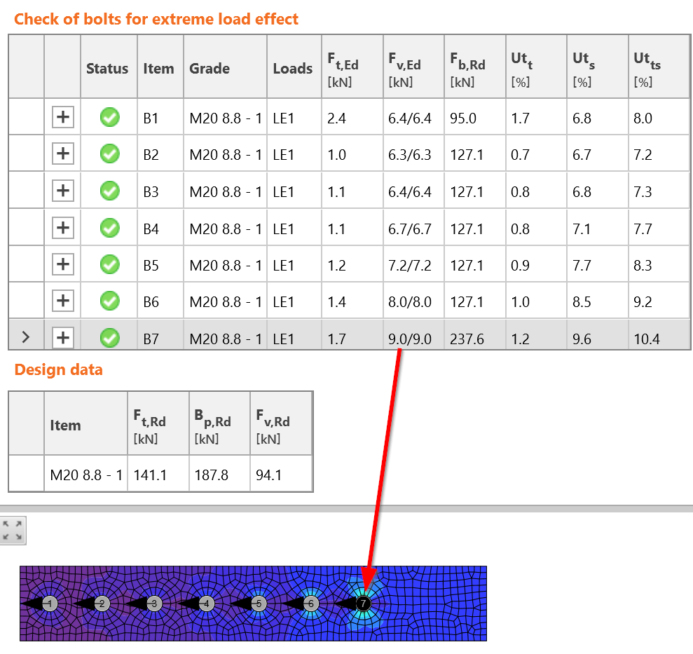
Cel mai solicitat șurub este B7, care se află într-adevăr la începutul grupului de șuruburi. Încărcarea care acționează la fiecare plan de forfecare este de 9 kN, adică 18 kN la șurubul B7. Aceasta este mai mare decât valoarea estimată de 14,72 kN. Se pare că IDEA StatiCa oferă o distribuție mai conservatoare a forței în șuruburi; cu toate acestea, aceasta se poate modifica la încărcări consecutive, datorită calculului neliniar și diagramei neliniare forță-deformație a șurubului la forfecare.