Módulo de aprendizaje: Pernos cargados a cortante (EN)
Introducción
Los pernos se utilizan habitualmente como elementos de fijación que conectan elementos de acero en uniones de montaje. Facilitan la rápida construcción de estructuras de acero. Los contratistas generalmente exigen que todas las uniones en obra sean atornilladas; en otras palabras, debe evitarse la soldadura en campo, a pesar de que las uniones atornilladas pueden ser mucho más complicadas que las uniones soldadas y requieren más material.
El objetivo de este módulo de aprendizaje es familiarizar a los estudiantes y darles confianza en el diseño de uniones atornilladas simples mediante la interacción con software de diseño de uniones que proporciona retroalimentación visual. Los estudiantes deben estar familiarizados con los fundamentos del diseño según el Eurocódigo – para más información, consultar p. ej. las notas de clase ESDEP.
Ejemplo: Pernos a cortante
Calcular la carga sobre los pernos y verificar el perno más solicitado.
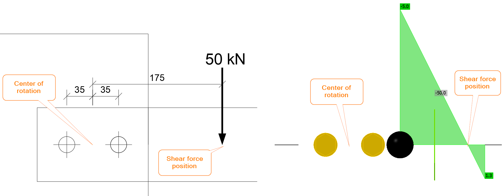
Geometría
Una placa de 20 mm de espesor se conecta a un voladizo formado por dos placas de 8 mm de espesor cada una mediante dos pernos M20 8.8. El voladizo está cargado por una fuerza de 50 kN a una distancia de 100 mm del borde de la placa. Los agujeros de los pernos son estándar (\(d_0=22\textrm{ mm}\)) y la fuerza cortante pasa a través de la zona roscada.
Solución
Es fundamental la determinación del centro de rotación y la carga sobre cada perno. Se supone que el centro de rotación de un grupo de pernos cargado a cortante se encuentra en el centro. La unión atornillada está cargada por una fuerza cortante y un momento flector. La fuerza cortante es \(V=50\textrm{ kN}\) y el momento flector es \(M=50\cdot 0.175=8.75 \textrm{kNm}\). En IDEA StatiCa, la posición de la fuerza cortante debe establecerse correctamente o la unión debe cargarse con una combinación de fuerza cortante y momento flector.
La fuerza cortante se transmite a través de los pernos de forma uniforme, es decir, cada perno transmite la misma parte de la carga cortante:
\[F_{1,V}=V_{Ed}/n_b=50/2=25\textrm{ kN}\]
donde:
- \(V_{Ed}\) – fuerza cortante aplicada
- \(n_b\) – número de pernos
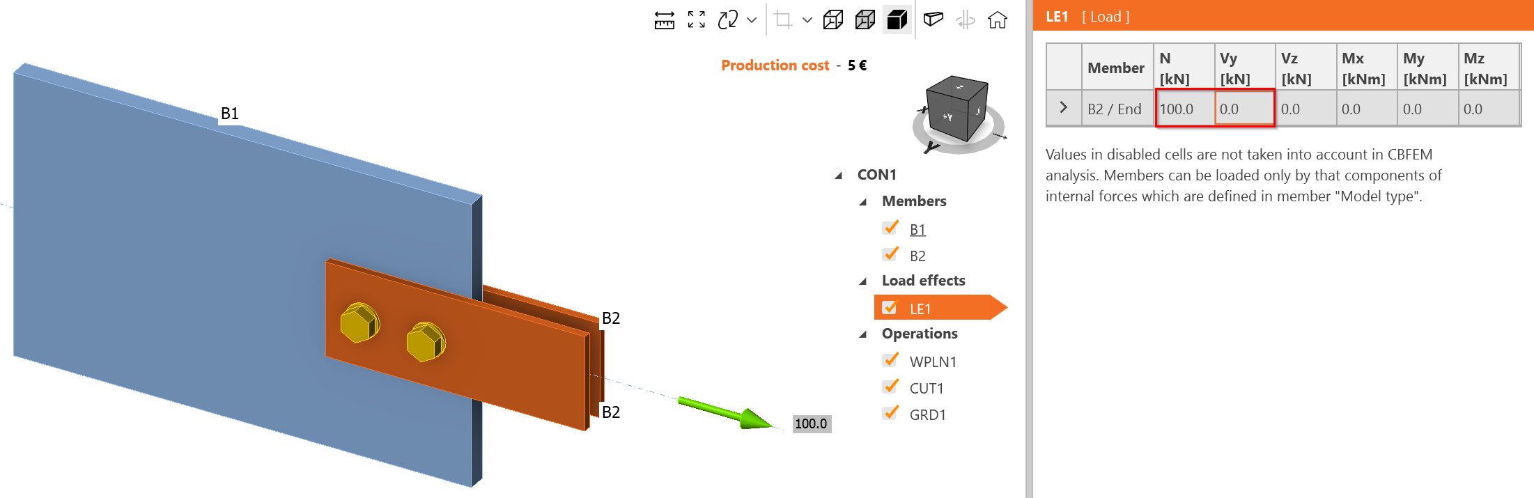
En IDEA StatiCa, si la posición de la fuerza cortante se establece en Pernos, el grupo de pernos está cargado únicamente a cortante:
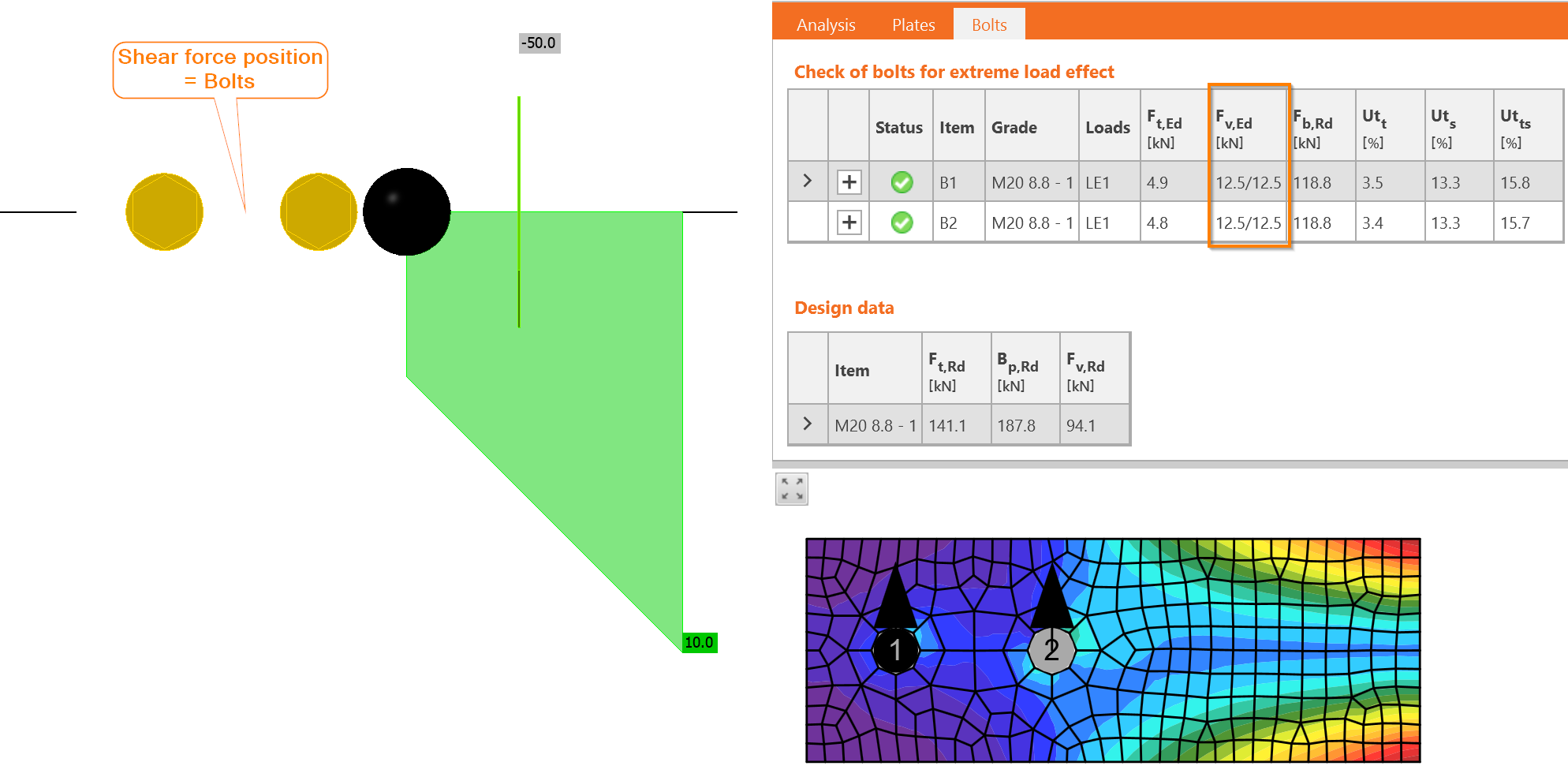
Las fuerzas son efectivamente idénticas y cada perno está cargado con 12,5/12,5, es decir, 12,5 kN en cada plano de cortante.
El momento flector también se transmite a través del grupo de pernos. Cada perno se carga proporcionalmente a la distancia del perno al centro de rotación. En este ejemplo, hay solo dos pernos con distancia idéntica:
\[r_i=p/2=70/2=35\textrm{ mm}\]
donde:
- \(r_i\) – distancia del perno al centro de rotación
- \(p\) – separación entre pernos
La fuerza que actúa sobre cada perno, \(F_{1,M}\), se calcula:
\[F_{1,M}=M_{Ed}\frac{r_1}{\Sigma r_i^2}=8.75\frac{0.035}{0.035^2+0.035^2}=125\textrm{ kN}\]
donde:
- \(M_{Ed}\) – momento flector que actúa sobre la unión
- \(r_1\) – distancia del perno analizado al centro de rotación
- \(r_i\) – distancia de cada perno al centro de rotación
A pesar de que el punto de aplicación de la carga está bastante próximo, a solo 100 mm del borde de la placa, la fuerza en el perno resultante del momento flector es muy grande.
En IDEA StatiCa, la unión puede cargarse únicamente con momento flector:
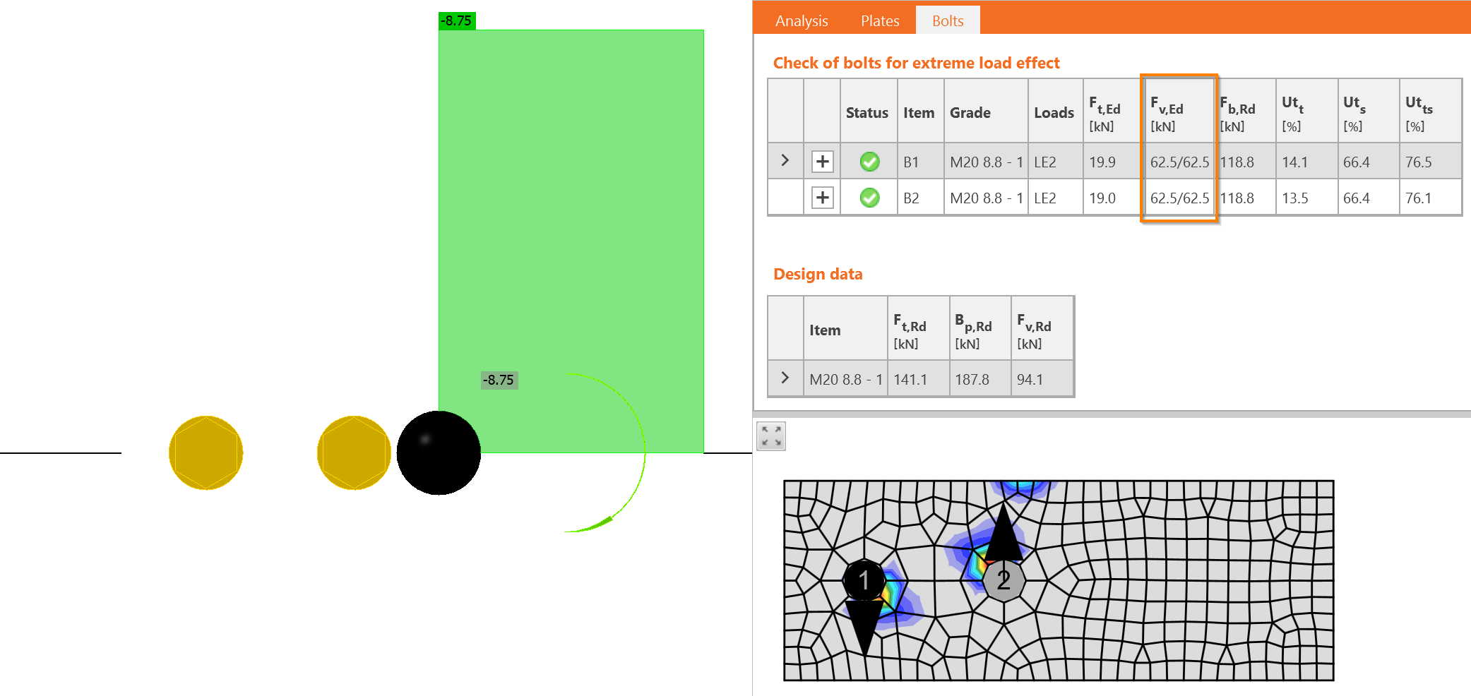
Ahora debemos realizar la suma vectorial de ambos efectos – fuerza cortante y momento flector. La dirección de las fuerzas es fundamental aquí. Las fuerzas en los pernos debidas a la fuerza cortante \(V_{Ed}\) actúan hacia abajo, mientras que las fuerzas debidas al momento flector rotan alrededor del centro de rotación. Esto significa que una actúa hacia arriba y la otra hacia abajo. La fuerza en un perno se resta: \(F_{1,v,Ed} = 25 - 125 = - 100\textrm{ kN}\), y la fuerza en el otro perno se suma: \(F_{2,v,Ed} = 25 + 125 = 150\textrm{ kN}\).
Exactamente las mismas fuerzas cortantes se obtienen en IDEA StatiCa.
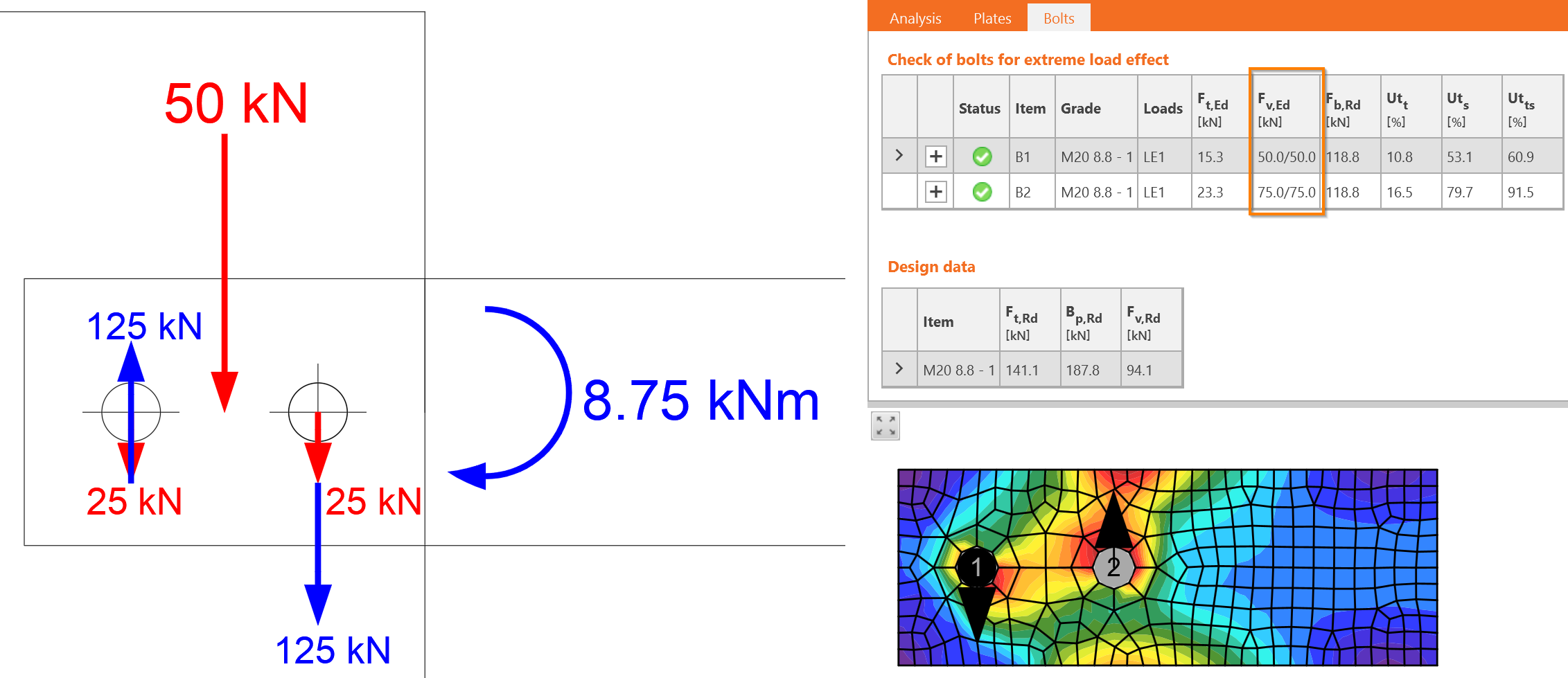
La fuerza mayor determina el diseño, \(F_{v,Ed}=F_{2,v,Ed}=150\textrm{ kN}\).
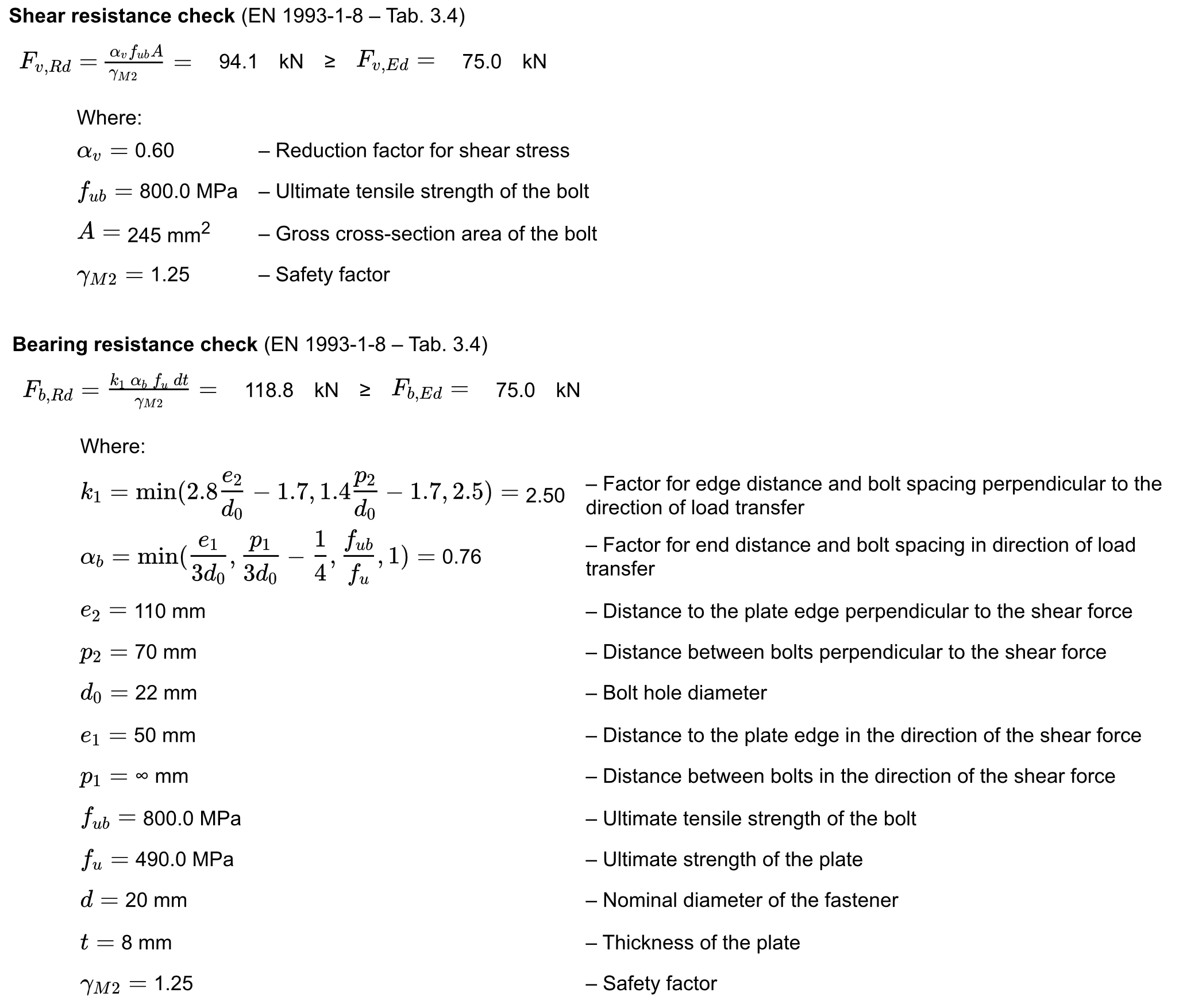
Se proporcionan verificaciones detalladas para el perno B2. Los pernos cargados a cortante deben verificarse para:
- Resistencia a cortante
- Resistencia al aplastamiento
Laboratorio Virtual – Pernos a Cortante
Cambie el efecto de carga a carga de tracción únicamente, 100 kN.
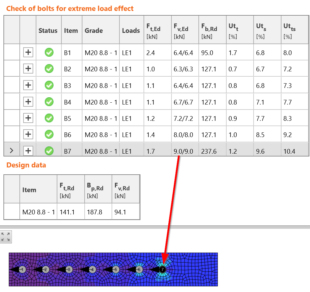
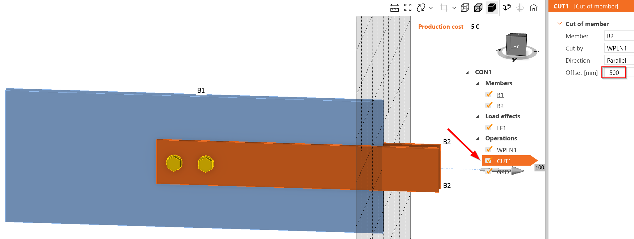
Cree una unión atornillada larga. Una unión atornillada larga es aquella con una longitud superior a \(15\cdot d = 15\cdot 20 = 300\textrm{ mm}\). Amplíe el solape de los elementos:
Añada más pernos con una separación de 70 mm:
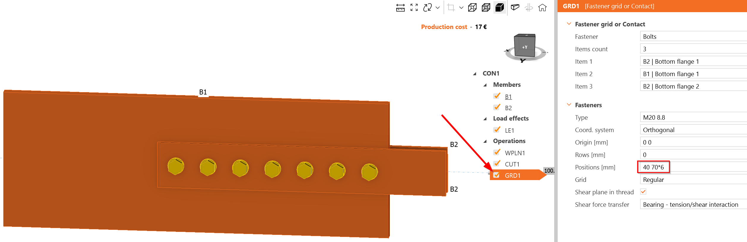
El perno más cargado es B7, que efectivamente se encuentra al inicio del grupo de pernos. La carga que actúa en cada plano de cortante es de 9 kN, es decir, 18 kN en el perno B7. Esto es más que los 14,72 kN estimados. Parece que IDEA StatiCa proporciona una distribución de fuerzas en los pernos más conservadora; sin embargo, puede cambiar con cargas consecutivas debido al cálculo no lineal y al diagrama no lineal carga-deformación del perno a cortante.