Tanulási modul: Nyírásra terhelt csavarok (EN)
Bevezetés
A csavarokat általánosan alkalmazzák kötőelemként acél elemek összekötésére szerelési kapcsolatokban. Lehetővé teszik az acélszerkezetek gyors építését. A kivitelezők jellemzően megkövetelik, hogy az építési helyszínen minden kapcsolat csavarkötéses legyen; más szóval, a helyszíni hegesztést kerülni kell, annak ellenére, hogy a csavarkötések sokkal bonyolultabbak lehetnek a hegesztett kapcsolatoknál, és több anyagot igényelnek.
Ennek a tanulási modulnak a célja, hogy a hallgatók megismerjék és magabiztosan tervezzék az egyszerű csavarkötéseket a kapcsolattervező szoftverrel való interakción keresztül, amely vizuális visszajelzést nyújt. A hallgatóknak ismerniük kell az Eurocode szerinti tervezés alapjait – további információkért lásd pl. ESDEP előadásjegyzetek.
Példa: Nyírásra terhelt csavarok
Számítsa ki a csavarokra ható erőt, és ellenőrizze a legjobban terhelt csavart.
Geometria
Egy 20 mm vastagságú lemezt két darab M20 8.8 csavarral kötnek össze egy konzollal, amely két darab 8 mm vastagságú lemezből áll. A konzolt 50 kN erő terheli a lemez szélétől 100 mm távolságra. A csavarlyukak szabványosak (\(d_0=22\textrm{ mm}\)), és a nyíróerő a meneteken halad át.
Megoldás
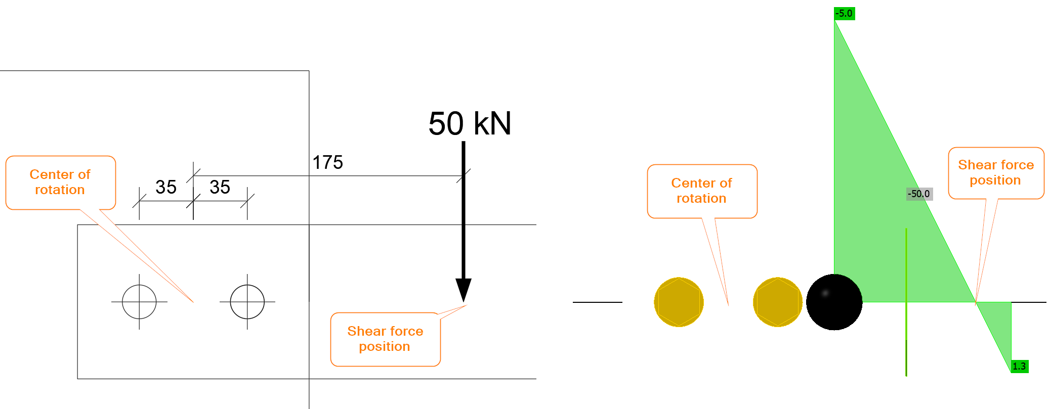
Döntő fontosságú a forgásközéppont meghatározása és az egyes csavarokra ható terhelés. A nyírásra terhelt csavarcsoport forgásközpontja feltételezhetően a középpontban van. A csavarkötést nyíróerő és hajlítónyomaték terheli. A nyíróerő \(V=50\textrm{ kN}\), a hajlítónyomaték \(M=50\cdot 0.175=8.75 \textrm{kNm}\). Az IDEA StatiCa programban a nyíróerő helyzetét helyesen kell beállítani, vagy a kapcsolatot nyíróerő és hajlítónyomaték kombinációjával kell terhelni.
A nyíróerőt a csavarok egyenletesen veszik fel, azaz minden csavar a nyíróterhelés azonos részét viseli:
\[F_{1,V}=V_{Ed}/n_b=50/2=25\textrm{ kN}\]
ahol:
- \(V_{Ed}\) – méretezési nyíróerő
- \(n_b\) – csavarok száma
Az IDEA StatiCa programban, ha a nyíróerő helyzete Csavarokra van beállítva, a csavarcsoport tisztán nyírásra terhelt:
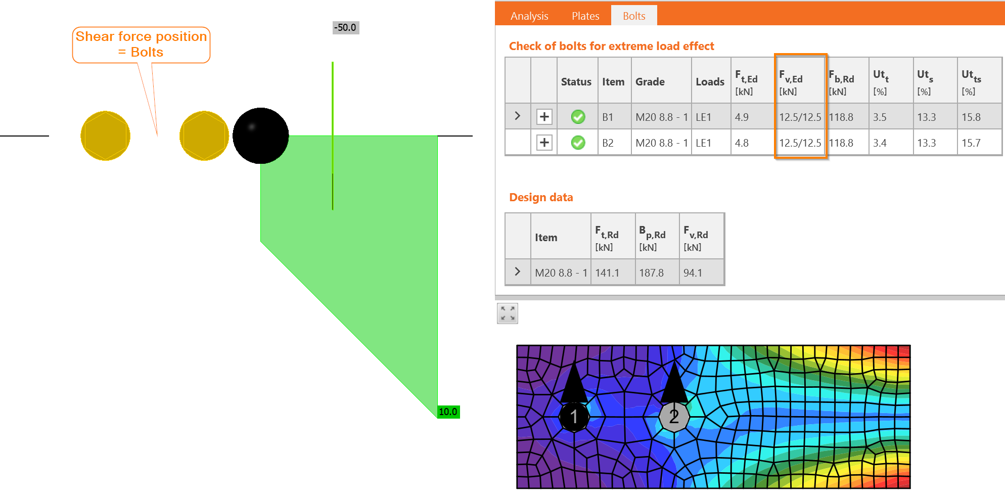
Az erők valóban azonosak, és minden csavar 12,5/12,5, azaz 12,5 kN erőt vesz fel minden nyírási síkban.
A hajlítónyomatékot szintén a csavarcsoport veszi fel. Minden csavar a forgásközépponttól mért távolságával arányosan terhelt. Ebben a példában csak két csavar van, azonos távolsággal:
\[r_i=p/2=70/2=35\textrm{ mm}\]
ahol:
- \(r_i\) – csavar távolsága a forgásközépponttól
- \(p\) – csavartávolság
Az egyes csavarokra ható erő, \(F_{1,M}\), kiszámítása:
\[F_{1,M}=M_{Ed}\frac{r_1}{\Sigma r_i^2}=8.75\frac{0.035}{0.035^2+0.035^2}=125\textrm{ kN}\]
ahol:
- \(M_{Ed}\) – a kapcsolatra ható hajlítónyomaték
- \(r_1\) – a vizsgált csavar távolsága a forgásközépponttól
- \(r_i\) – minden csavar távolsága a forgásközépponttól
Annak ellenére, hogy a terhelés alkalmazási pontja meglehetősen közel van, mindössze 100 mm-re a lemez szélétől, a hajlítónyomatékból eredő csavarerő igen nagy.
Az IDEA StatiCa programban a kapcsolat csak hajlítónyomatékkal terhelhető:
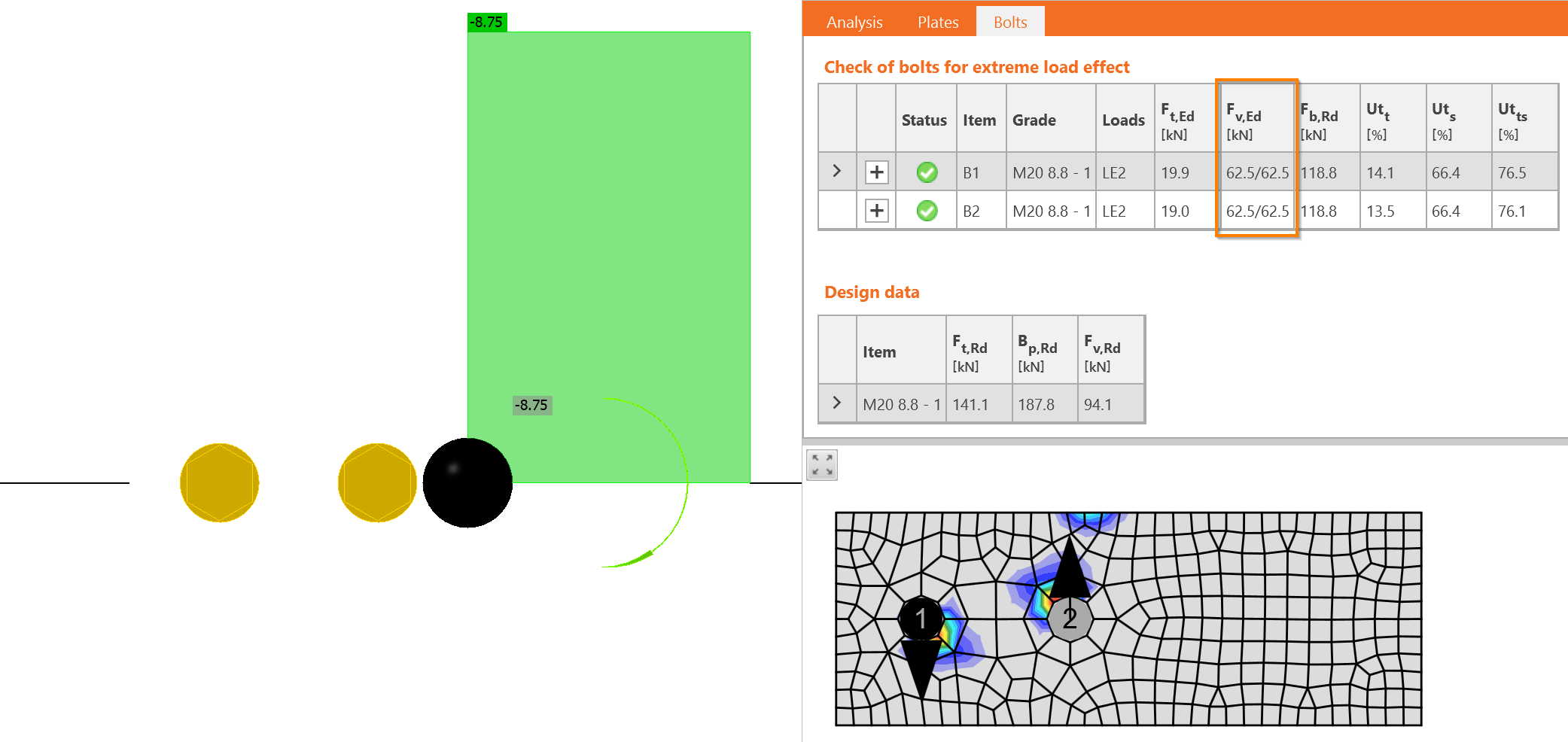
Most mindkét hatás – a nyíróerő és a hajlítónyomaték – vektoriális összegét kell elvégezni. Az erők iránya itt döntő fontosságú. A nyíróerőből \(V_{Ed}\) eredő csavarerők lefelé hatnak, míg a hajlítónyomatékból eredő erők a forgásközéppont körül forognak. Ez azt jelenti, hogy az egyik felfelé, a másik lefelé hat. Az egyik csavar ereje kivonódik: \(F_{1,v,Ed} = 25 - 125 = - 100\textrm{ kN}\), a másik csavar ereje összeadódik: \(F_{2,v,Ed} = 25 + 125 = 150\textrm{ kN}\).
Pontosan ugyanezek a nyíróerők szerepelnek az IDEA StatiCa programban is.
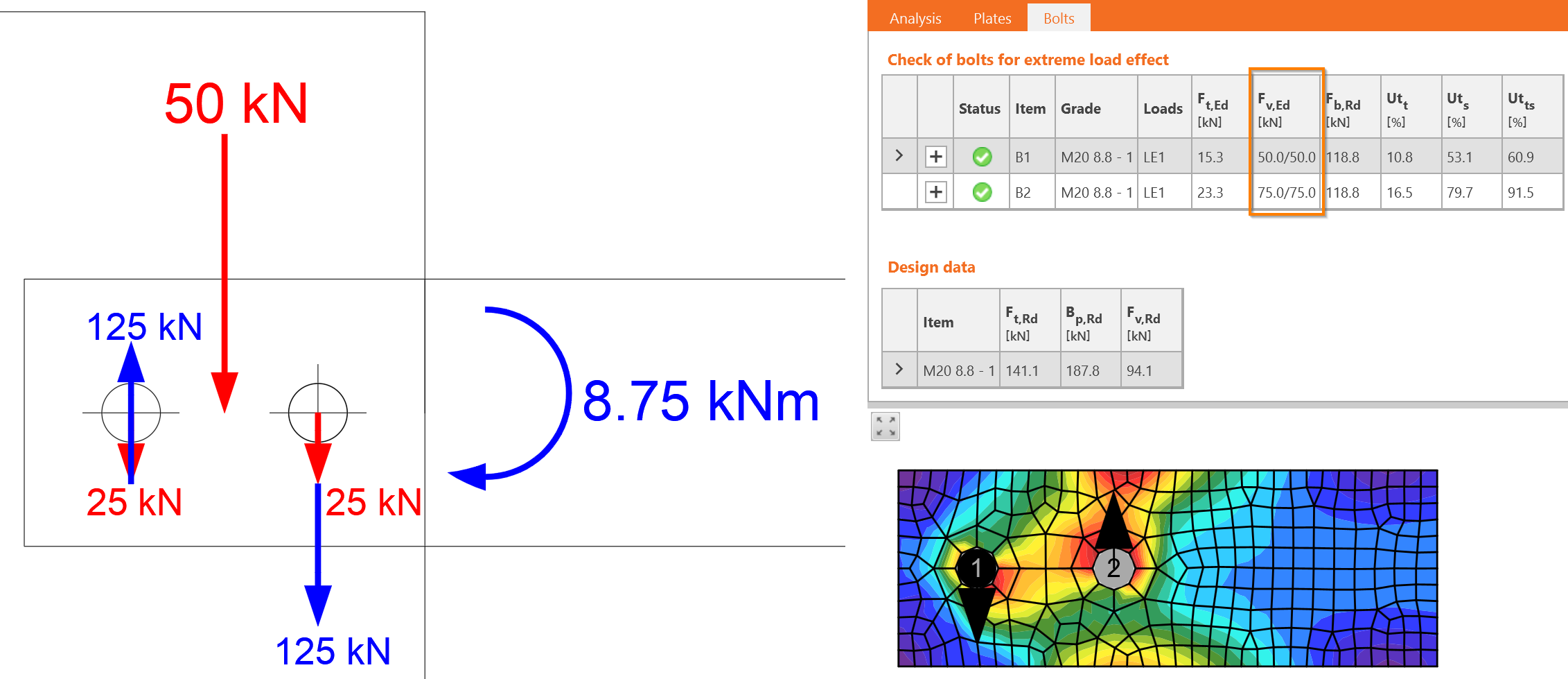
A nagyobb erő határozza meg a méretezést: \(F_{v,Ed}=F_{2,v,Ed}=150\textrm{ kN}\).
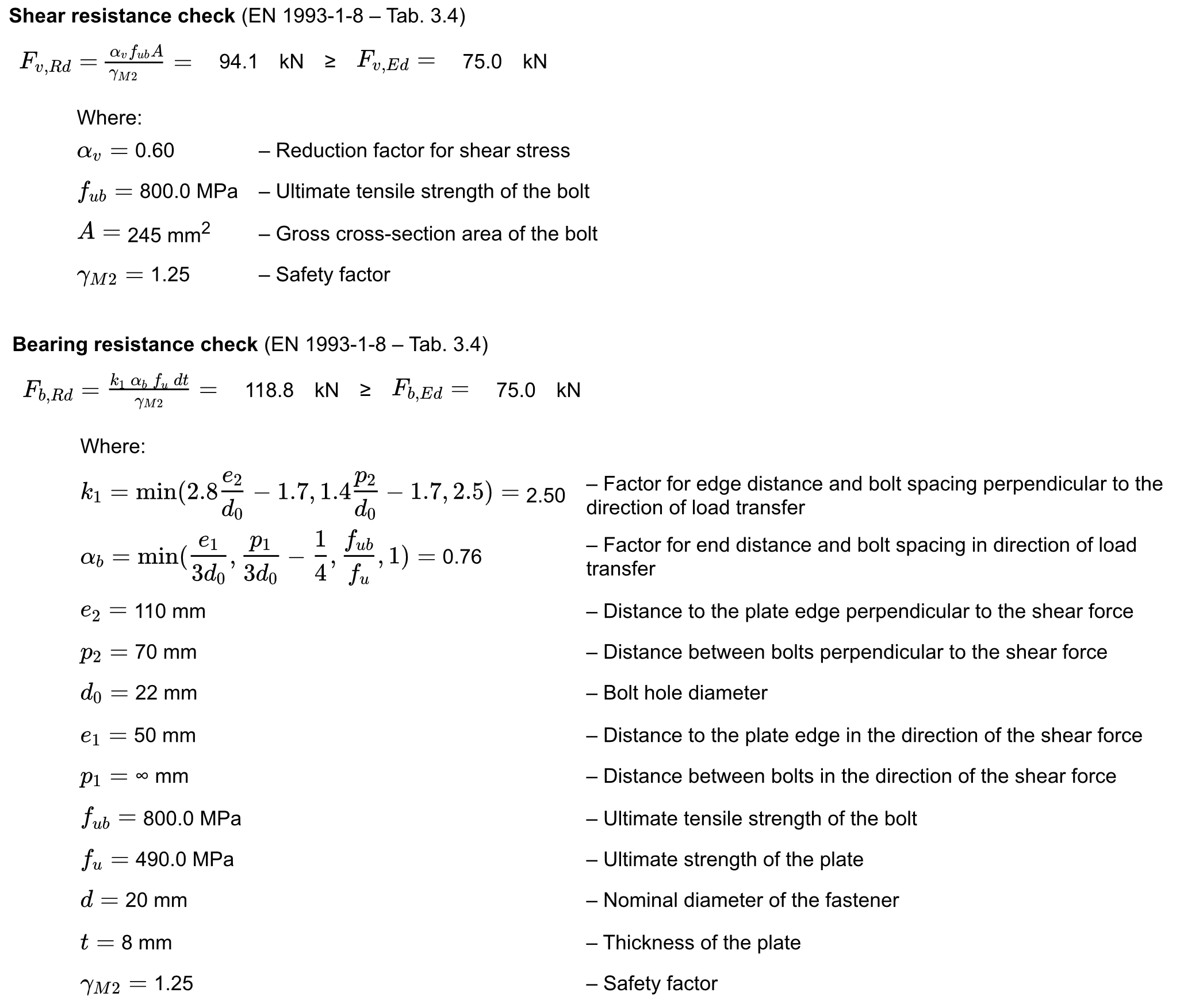
A B2 csavar részletes ellenőrzése elvégzésre kerül. A nyírásra terhelt csavarokat a következőkre kell ellenőrizni:
- Nyírási ellenállás
- Palástnyomási ellenállás
Virtuális labor – Nyírásra terhelt csavarok
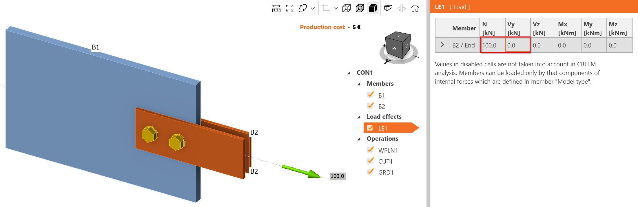
Változtassa meg a teherhatást csak húzóterhelésre, 100 kN értékre.
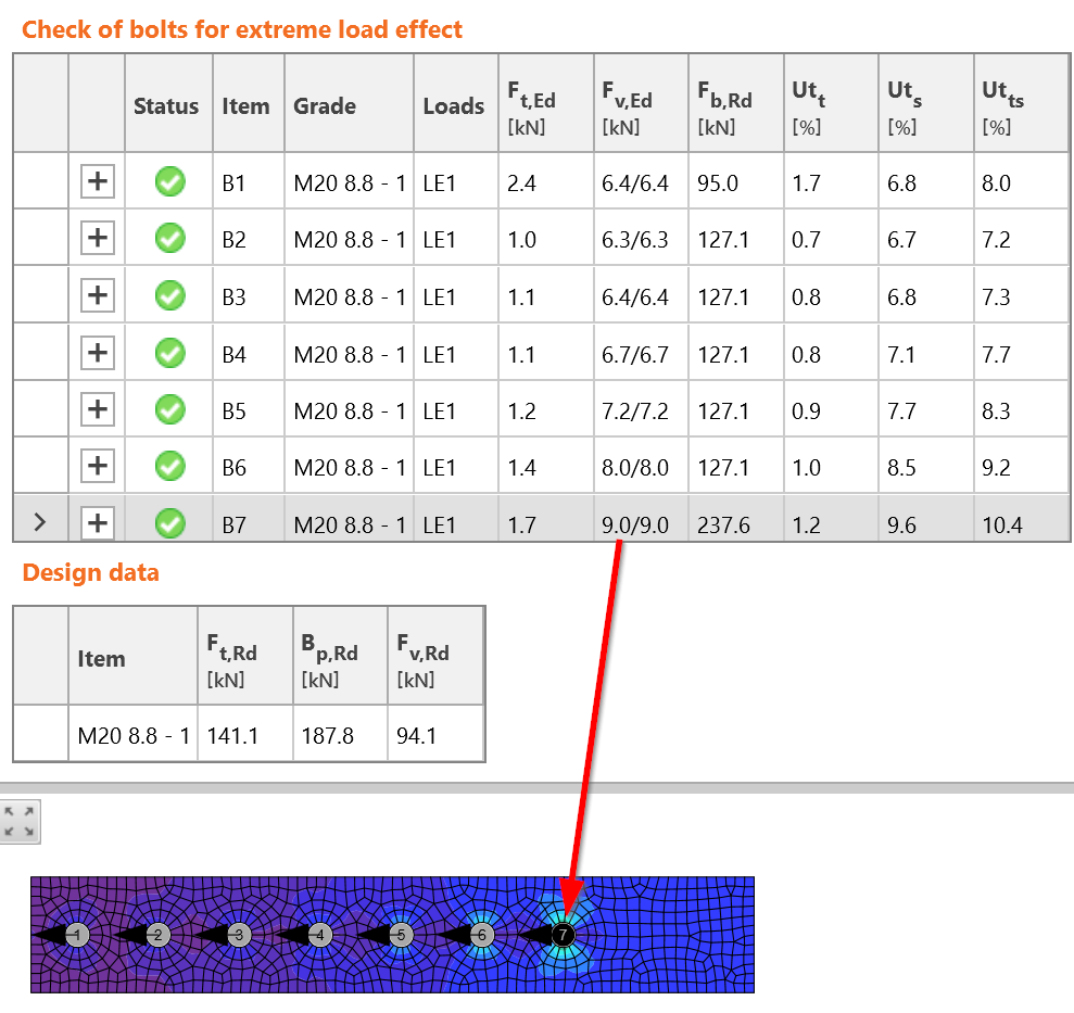
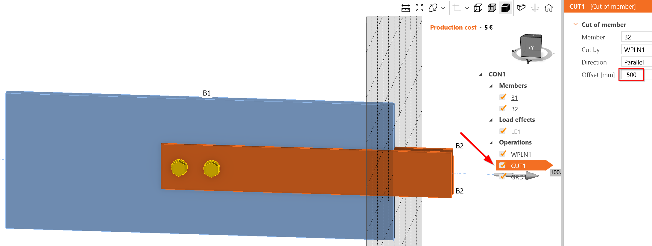
Hozzon létre hosszú csavarkötést. A hosszú csavarkötés hosszabb, mint \(15\cdot d = 15\cdot 20 = 300\textrm{ mm}\). Növelje meg a szerkezeti elemek átfedését:
Adjon hozzá több csavart 70 mm-es osztással:
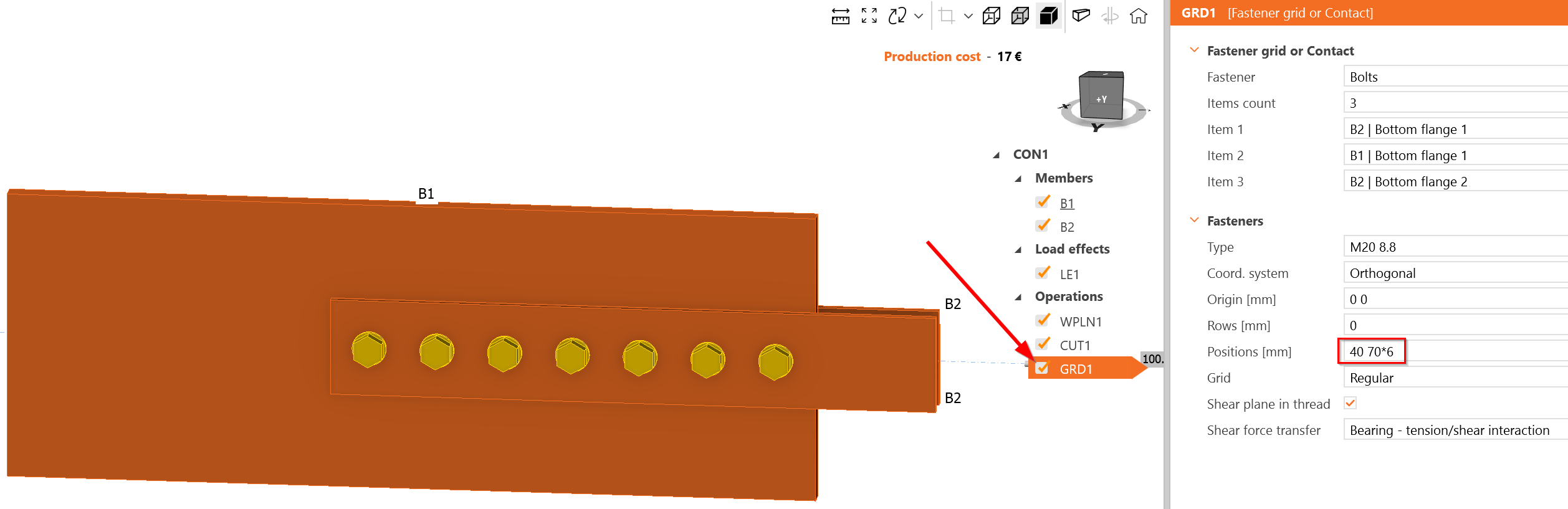
A legjobban terhelt csavar a B7, amely valóban a csavarcsoport elején helyezkedik el. Az egyes nyírási síkokon ható terhelés 9 kN, azaz a B7 csavarnál 18 kN. Ez több, mint a becsült 14,72 kN. Úgy tűnik, hogy az IDEA StatiCa konzervatívabb csavarerő-eloszlást ad; azonban ez változhat az egymást követő terhelések hatására a nemlineáris számítás és a csavar nyírásban mutatott nemlineáris terhelés-alakváltozás diagramja miatt.