Berekeningsaannames
Het gedrag van een gewapend betonnen doorsnede onderworpen aan torsie kan worden onderverdeeld in twee categorieën - vóór en na het moment waarop scheuren voor het eerst worden verwacht. Vóór een scheur gedraagt de doorsnede zich als een elastisch materiaal. De torsiespanning kan worden uitgedrukt door de formule
\[\tau =~\frac{{{T}_{Ed}}}{{{W}_{t}}}\]
waarbij Wt het doorsnede-weerstandsmoment voor torsie is.
Scheuren in het ongewapende staaf als gevolg van de maatgevende hoofdtrekspanning door torsie vormen tevens een uiterste grenstoestand. Het gedrag van een gewapend betonnen doorsnede onderworpen aan torsie kan worden beschreven op basis van een dunwandige gesloten doorsnede, zie onderstaande figuur.
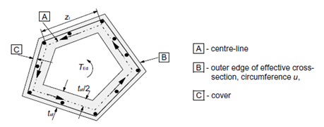
\[ \textsf{\textit{\footnotesize{\qquad Equivalent thin-walled cross-section.}}}\]
Berekeningsmethode
Het proces van een normtoetsing van een gewapend betonnen doorsnede voor torsie is zeer vergelijkbaar met de normtoetsing voor afschuiving. Allereerst controleren we de betonweerstand. Als de betoncontrole is voldaan, kan de wapening worden ontworpen aan de hand van de constructieve regels. Anders moeten we de wapening en de weerstand van de drukdiagonaal via berekening verifiëren.
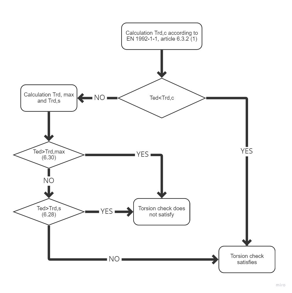
\[ \textsf{\textit{\footnotesize{\qquad Process diagram for torsion check.}}}\]
Weerstand
De afschuifstroom in een wand van een dunwandige doorsnede onder torsie kan worden uitgedrukt als:
\[ {{\tau }_{t}}{{t}_{ef}}=~\frac{{{T}_{Ed}}}{2{{A}_{k}}}\]
De afschuifkracht in een wand van een dunwandige doorsnede kan worden uitgedrukt als:
\[ V={{\tau }_{t}}{{t}_{ef}}z\]
Waarbij
τ Afschuifstroom in de wand,
tef is de effectieve wanddikte,
z is de zijlengte van de wand,
TEd is het torsie-moment,
Ak is het oppervlak omsloten door de hartlijnen van de verbindende wanden, inclusief inwendige holle gebieden.
Het torsie-scheurmoment, dat kan worden bepaald door fctd in te vullen in de vorige uitdrukking. Zo verkrijgen we de uitdrukking voor de weerstand bij torsie zonder torsiebewapening.
\[ {{T}_{Rd,c}}=2{{A}_{k}}{{t}_{ef}}{{f}_{ctd}}\]
waarbij fctd rekenwaarde van de axiale treksterkte van beton
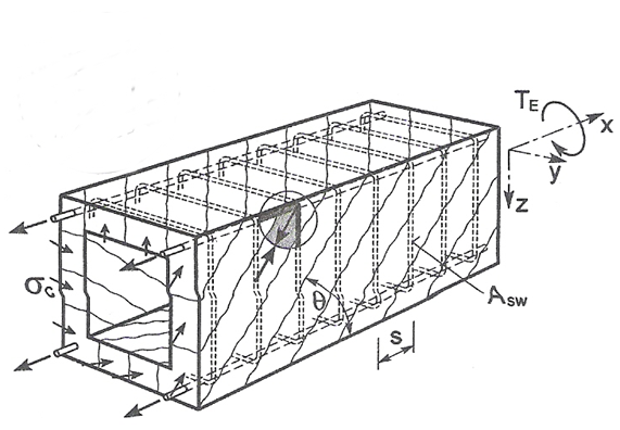
\[ \textsf{\textit{\footnotesize{\qquad Principles of Truss analogy for member under torsion moment.}}}\]
De weerstand van de staaf met torsiebewapening is samengesteld uit de weerstand van de drukdiagonalen in het beton, die wederom is gebaseerd op de vakwerkanalogie. De drukspanning in de diagonaal kan worden uitgedrukt met behulp van de afschuifkracht in de wand van een dunwandige doorsnede op het beschouwde wandoppervlak, d.w.z.
\[{{\sigma }_{c}}=\frac{\frac{{{T}_{Ed}}z}{2{{A}_{k}}\sin \theta }}{z~{{t}_{ef}}\cos \theta }=\frac{{{T}_{Ed}}}{2{{A}_{k}}{{t}_{ef}}\sin \theta \cos \theta }\]
Substitutie van σc=σcwfcd en TEd=TRd,max en het uitdrukken van TRd,max geeft een vergelijking voor de weerstand van de drukdiagonaal
\[{{T}_{Rd,max}}=2~\nu ~{{\alpha }_{cw}}~{{f}_{cd}}~{{A}_{k}}~{{t}_{ef~\sin \theta ~\cos \theta }}\]
waarbij
ν = 0,6 voor fck ≤ 60MPa of voor fck > 60MPa
αcw coëfficiënt die rekening houdt met de toestand van de drukspanning in de drukgordel
fcd rekenwaarde van de betondruksterkte
de weerstand van de afschuifwapening onderworpen aan torsie is wederom gebaseerd op de spanning in de drukdiagonaal. De beugel kracht is gelijk aan de spanning in de gedrukte diagonaal op het oppervlak dat overeenkomt met de betreffende beugelrij, d.w.z.
\[{{A}_{sw}}{{f}_{ywd}}=\frac{{{T}_{Ed}}}{2{{A}_{k}}{{t}_{ef}}\sin \theta \cos \theta }~{{t}_{ef}}~s{{\sin }^{2}}\theta =\frac{{{T}_{Ed}}~s}{2{{A}_{k}}\cot \theta }~\]
Substitutie van TEd=TRd,s en het uitdrukken van TRd,s geeft de vergelijking:
\[{{T}_{Rd,s}}=2{{A}_{k}}\frac{{{A}_{sw}}{{f}_{ywd}}}{s}~\cot \theta\]
Als de hoeveelheid langswapening en afschuifwapening bekend is, kunnen we de hoek θ bepalen met de uitdrukking
\[{{\tan }^{2}}\theta =\frac{\frac{{{A}_{sw}}{{f}_{ywd}}}{s}}{\frac{{{A}_{sl}}{{f}_{yd}}}{{{u}_{k}}}}\]
Substitutie voor TRd,s geeft
\[{{T}_{Rd,s}}=2{{A}_{k}}\sqrt{\frac{{{A}_{sw}}}{s}{{f}_{ywd~}}\frac{{{A}_{sl}}}{{{u}_{k}}}~{{f}_{yd}}}\]
Waarbij
Asw oppervlak van de afschuifwapening
s is de hartafstand van de beugels van de afschuifwapening
fywd is de effectieve rekensterkte van de afschuifwapening
Asl oppervlak van de langswapening
uk is de buitenomtrek van de doorsnede
fywd is de effectieve rekensterkte van de langswapening
De kracht in de langswapening kan worden afgeleid uit de afschuifkracht in een wand van een doorsnede onderworpen aan een zuiver torsie-moment, die als volgt wordt gegeven:
\[V=\frac{{{T}_{Ed}}}{2{{A}_{k}}}{{u}_{k}}\]
Die kracht wordt omgezet naar de langsrichting en we verkrijgen:
\[{{F}_{l}}=\frac{{{T}_{Ed}}{{u}_{k}}}{2{{A}_{k}}~\tan \theta }\]
Het toegestane bereik van de waarden voor hoek θ is vergelijkbaar met de afschuifcontrole, d.w.z. 1 < cot θ < 2,5. De afhankelijkheid tussen de weerstanden is te zien in onderstaande figuur. Het diagram toont dat bij toenemende hoek θ de weerstand TRd,max toeneemt, de weerstand TRd.s afneemt en de weerstand TRd,c constant blijft, omdat deze niet is gebaseerd op de vakwerkanalogie.
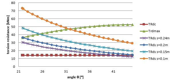
\[ \textsf{\textit{\footnotesize{\qquad Závislost únosnosti průřezu v kroucení na úhlu θ.}}}\]
Berekening van doorsnede-eigenschappen voor torsie
Om de doorsnede te controleren op torsie is het noodzakelijk een zogenaamde equivalente dunwandige gesloten doorsnede op te stellen. Bij het bepalen van de afmetingen van de equivalente dunwandige doorsnede wordt uitgegaan van een rechthoekige vorm. Voor het werkelijke oppervlak van een rechthoek geldt A = b×h en voor de omtrek van een rechthoek u =2 (b +h). Met behulp van deze twee vergelijkingen kan het alternatieve dunwandige rechthoekige oppervlak en de omtrek van de oorspronkelijke doorsnede worden bepaald. Het oplossen van twee vergelijkingen met twee onbekenden geeft:
\[b=\frac{-u\pm \sqrt{{{u}^{2}}-16A}}{-4}\text{ }\!\!~\!\!\text{ }\]
\[h=\frac{\left( u-2\text{b} \right)}{2}\]
De wanddikte van de effectieve doorsnede kan worden bepaald uit de omtrek en het doorsnede-oppervlak als:
\[t=\text{A}/\text{u}\]
Vervolgens het oppervlak en de omtrek bepaald door de hartlijn van de effectieve doorsnede:
\[{{A}_{k}}=\left( \text{h}-\text{t} \right)\text{ }\!\!~\!\!\text{ }\left( \text{b}-\text{t} \right)\text{ }\!\!~\!\!\text{ }\]
\[{{u}_{k}}=2\left( \left( \text{h}-\text{t} \right)+\text{ }\!\!~\!\!\text{ }\left( \text{b}-\text{t} \right) \right)\]
Het probleem met deze methode doet zich voor bij een T-vormige doorsnede met een brede plaat, waarbij het totale oppervlak en de omtrek worden gebruikt om de afmetingen te berekenen (inclusief deze plaat). In toekomstige versies van het IDEA RCS programma zal de selectie van het meest massieve doorsnededeel worden mogelijk gemaakt, dat zal worden gebruikt voor de torsiecontrole.