Modello di piastra e convergenza della rete
L'aumento del numero di elementi fornisce risultati più precisi, ma a costo di una maggiore richiesta computazionale.
Modello di piastra
Gli elementi shell sono raccomandati per la modellazione delle piastre nell'analisi FEA del collegamento strutturale. Vengono applicati elementi shell quadrangolari a 4 nodi con nodi agli angoli. In ciascun nodo sono considerati sei gradi di libertà: 3 traslazioni (ux, uy, uz) e 3 rotazioni (φx, φy, φz). Le deformazioni dell'elemento sono suddivise nelle componenti membranale e flessionale.
La formulazione del comportamento membranale è basata sul lavoro di Ibrahimbegovic (1990). Vengono considerate le rotazioni perpendicolari al piano dell'elemento. È fornita una formulazione 3D completa dell'elemento. Le deformazioni a taglio fuori piano sono considerate nella formulazione del comportamento flessionale dell'elemento basata sull'ipotesi di Mindlin. Viene applicata una variante stabilizzata interna dell'elemento di piastra quadrangolare di Mindlin con deformazione a taglio costante lungo il bordo. Gli elementi sono ispirati agli elementi MITC4; si veda Dvorkin (1984). Lo shell è suddiviso in cinque strati di integrazione attraverso lo spessore della piastra in ciascun punto di integrazione e il comportamento plastico viene analizzato in ciascun punto. Questo metodo è denominato integrazione di Gauss–Lobatto. Lo stadio elastico-plastico non lineare del materiale viene analizzato in ciascuno strato sulla base delle deformazioni note. Vengono mostrate solo le tensioni e le deformazioni massime di tutti gli strati.
Convergenza della rete
Esistono alcuni criteri per la generazione della rete nel modello di collegamento. La verifica normativa del collegamento dovrebbe essere indipendente dalla dimensione degli elementi. La generazione della rete su una piastra separata è priva di problemi. Occorre prestare attenzione a geometrie complesse come pannelli irrigiditi, T-stub e piastre di base. Per geometrie complesse è opportuno eseguire un'analisi di sensibilità considerando la discretizzazione della rete.
Tutte le piastre di una sezione trasversale di trave hanno una suddivisione comune in elementi. La dimensione degli elementi finiti generati è limitata. La dimensione minima dell'elemento è impostata a 10 mm e la dimensione massima a 50 mm (può essere impostata in Code setup). Le reti su ali e anime sono indipendenti l'una dall'altra. Il numero predefinito di elementi finiti è impostato a 8 elementi per altezza della sezione trasversale, come mostrato nella figura seguente. L'utente può modificare i valori predefiniti in Code setup.
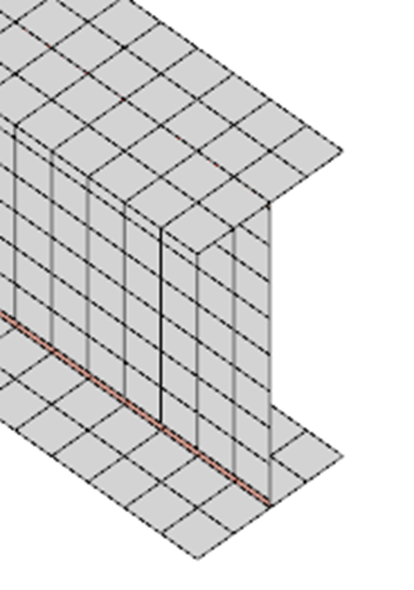
La rete su una trave con vincoli tra l'anima e la piastra dell'ala
La rete delle piastre d'estremità è separata e indipendente dalle altre parti del collegamento. La dimensione predefinita degli elementi finiti è impostata a 16 elementi per altezza della sezione trasversale, come mostrato nella figura.
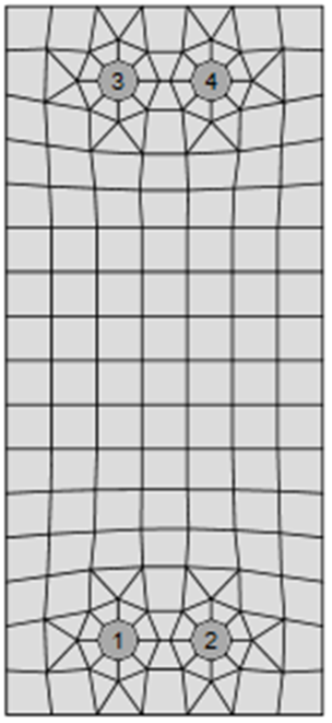
La rete su una piastra d'estremità con 7 elementi lungo la sua larghezza
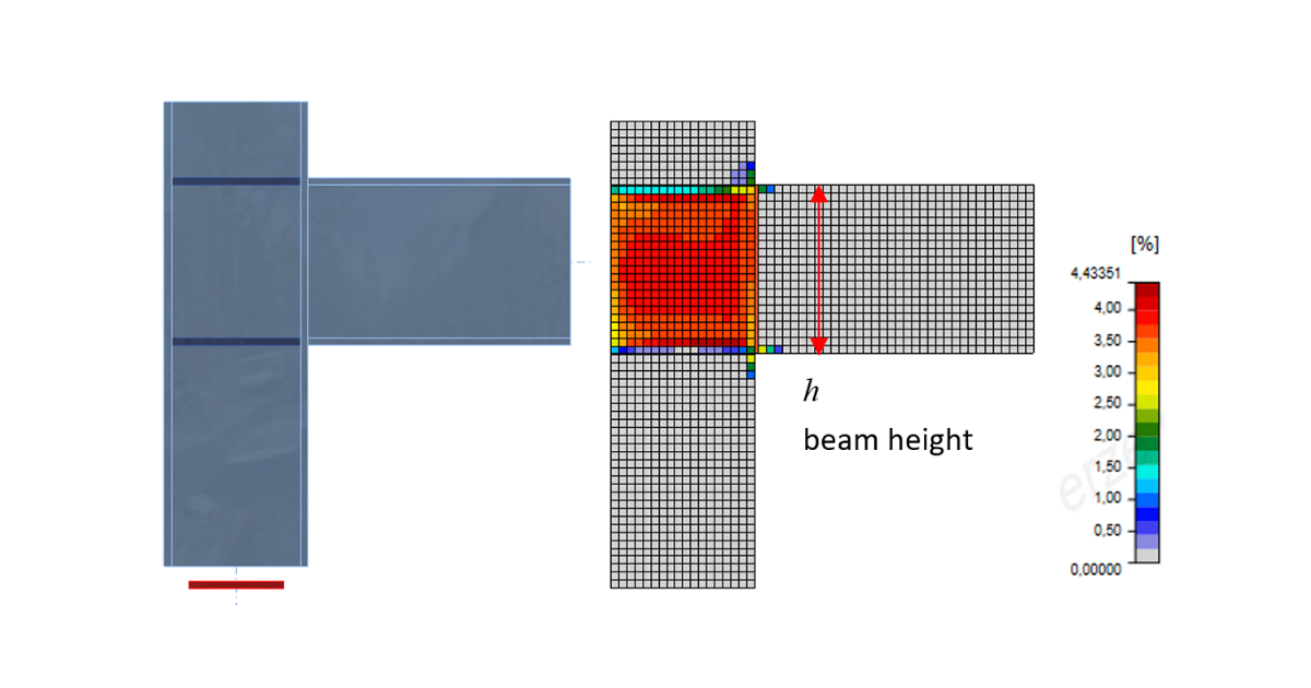
Il seguente esempio di un giunto trave-colonna mostra l'influenza della dimensione della rete sulla resistenza a momento. Una trave a sezione aperta IPE 220 è collegata a una colonna a sezione aperta HEA 200 e caricata da un momento flettente, come mostrato nella figura seguente. Il componente critico è il pannello d'anima della colonna a taglio. Il numero di elementi finiti lungo l'altezza della sezione trasversale varia da 4 a 40 e i risultati vengono confrontati. Le linee tratteggiate rappresentano la differenza del 5%, 10% e 15%. Si raccomanda di suddividere l'altezza della sezione trasversale in 8 elementi.
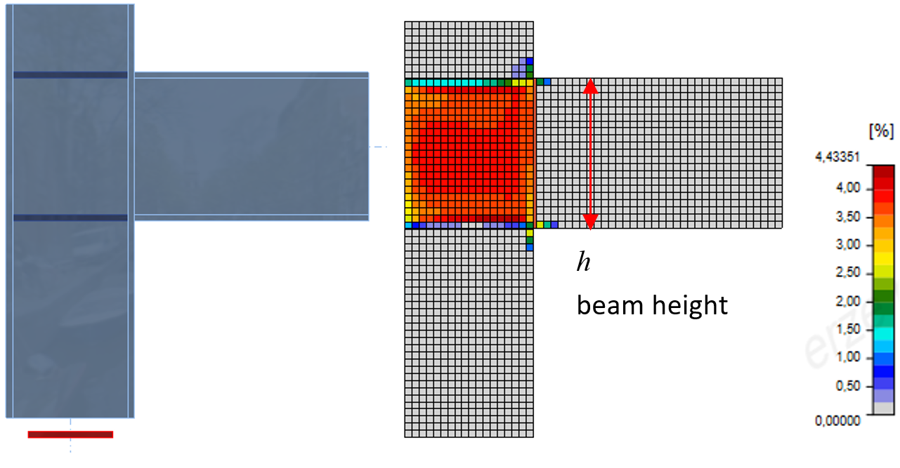
Modello di giunto trave-colonna e deformazioni plastiche allo stato limite ultimo
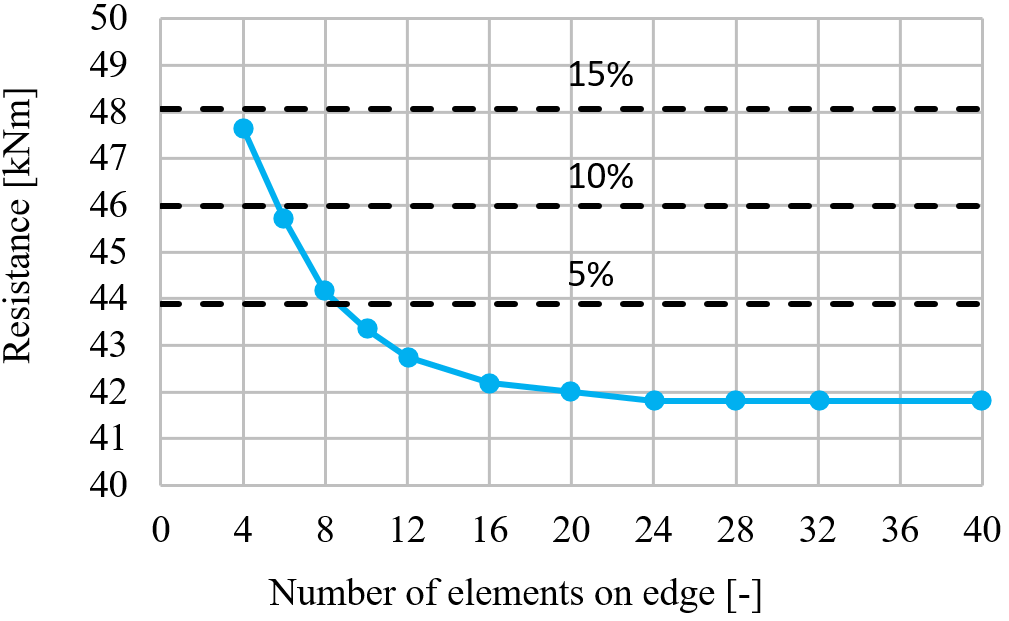
L'influenza del numero di elementi sulla resistenza a momento
Viene presentato lo studio di sensibilità della rete di un irrigidimento snello compresso del pannello d'anima della colonna. Il numero di elementi lungo la larghezza dell'irrigidimento varia da 4 a 20. Il primo modo di instabilità e l'influenza del numero di elementi sulla resistenza all'instabilità e sul carico critico sono mostrati nella figura seguente. Viene visualizzata la differenza del 5% e del 10%. Si raccomanda di utilizzare 8 elementi lungo la larghezza dell'irrigidimento.
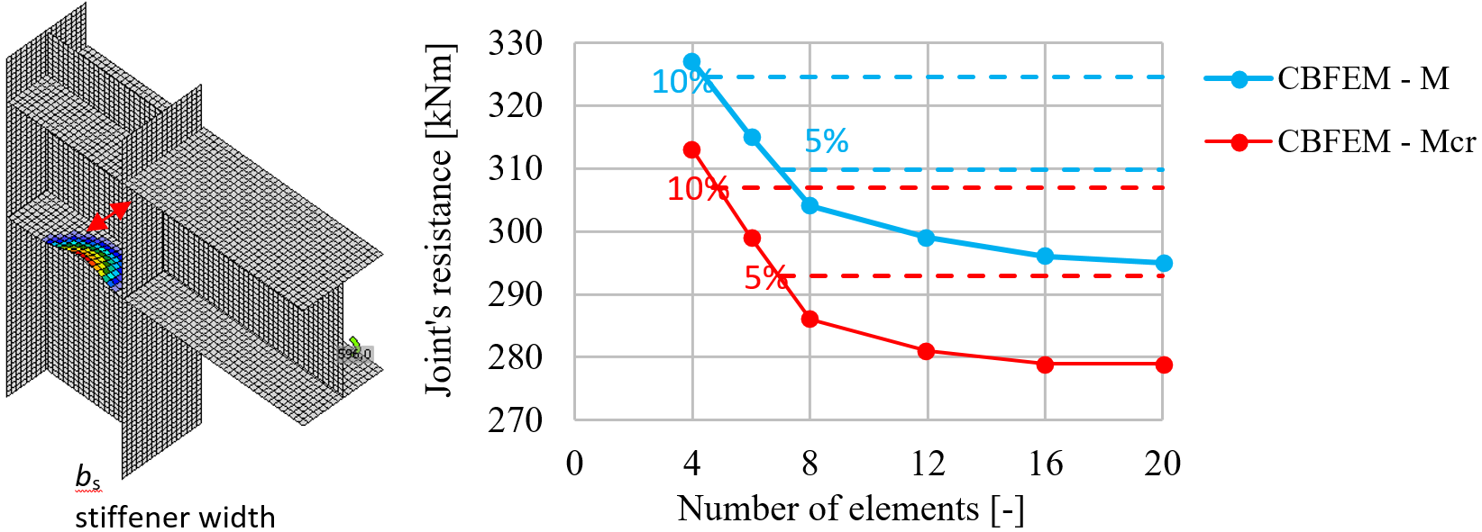
Il primo modo di instabilità e l'influenza del numero di elementi lungo l'irrigidimento sulla resistenza a momento
Viene presentato lo studio di sensibilità della rete di un T-stub in trazione. La metà della larghezza dell'ala è suddivisa in 8-40 elementi e la dimensione minima dell'elemento è impostata a 1 mm. L'influenza del numero di elementi sulla resistenza del T-stub è mostrata nella figura seguente. Le linee tratteggiate rappresentano la differenza del 5%, 10% e 15%. Si raccomanda di utilizzare 16 elementi sulla metà della larghezza dell'ala.
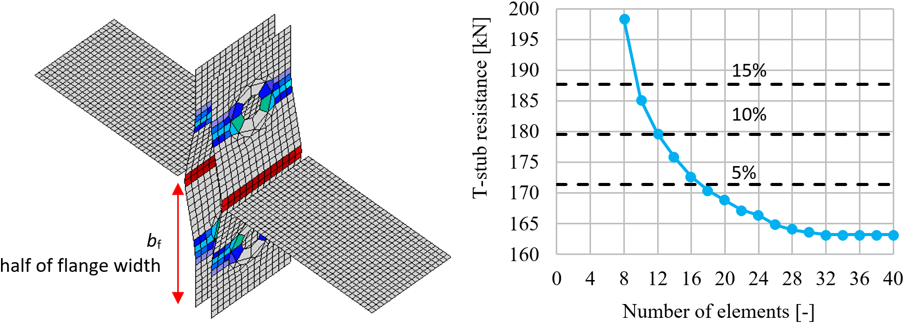
L'influenza del numero di elementi sulla resistenza del T-stub