Sarokvarrat fedőkötésben
Leírás
E fejezet célja a sarokvarrat fedőkötésben alkalmazott komponensalapú végeselem-módszer (CBFEM) ellenőrzése a komponensmódszerrel (CM). Két lemezt három konfigurációban kapcsolnak össze: harántvarrással, hosszirányú varrással, valamint harántvarrat és hosszirányú varrat kombinációjával. A varrat hossza és torokvastagsága a vizsgálat változó paraméterei. A tanulmány kiterjed a hosszú varratokra is, amelyek teherbírása a feszültségkoncentráció miatt csökkentett. A kapcsolatot normálerő terheli.
Analitikai modell
A sarokvarrat az egyetlen vizsgált komponens a tanulmányban. A varratokat úgy tervezték, hogy azok legyenek a kapcsolat leggyengébb komponensei. A varratot az EN 1993-1-8:2005 szerint tervezték. A sarokvarrat méretezési teherbírását az EN 1993-1-8:2005 4.5.3.2 pontjában megadott iránymódszerrel határozták meg. A sarokvarrat szilárdságának ellenőrzésére rendelkezésre álló számítási módszerek azon egyszerűsítő feltételezésen alapulnak, hogy a feszültségek egyenletesen oszlanak el a sarokvarrat torokkeresztmetszetében, ami a 4.1.1. ábrán látható normálfeszültségekhez és nyírófeszültségekhez vezet, az alábbiak szerint:
- σ⊥ a torokkeresztmetszetre merőleges normálfeszültség;
- σ∥ a varrat tengelyével párhuzamos normálfeszültség a keresztmetszetben;
- τ⊥ a varrat tengelyére merőleges nyírófeszültség (a torokkeresztmetszet síkjában);
- τ∥ a varrat tengelyével párhuzamos nyírófeszültség (a torokkeresztmetszet síkjában).
A tengellyel párhuzamos σ∥ normálfeszültséget a varrat méretezési teherbírásának ellenőrzésekor nem kell figyelembe venni.
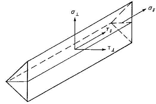
\[ \textsf{\textit{\footnotesize{Fig. 4.1.1 Stresses in a throat section of a fillet weld}}}\]
A sarokvarrat méretezési teherbírása elegendő, ha az alábbi feltételek mindegyike teljesül:
\[ \sqrt{\sigma_{\perp}^2 + 3 \cdot ( \tau_{\perp}^2 + \tau_{\perp}^2 )} \le \frac{f_\textrm{u}}{\beta_\textrm{w} \gamma_\textrm{M2}} \]
\[ \sigma_{\perp} \le \frac{0.9 f_\textrm{u}}{\gamma_\textrm{M2}} \]
A \( 150 \cdot a \)-nál hosszabb fedőkötéseknél a \(\beta_{\mathrm{Lw,1}}\) csökkentési tényező:
\( \beta_{\mathrm{Lw,1}} = 1.2 - \frac{0.2 L_\textrm{j}}{150 a} \) de \(\beta_{\mathrm{Lw,1}} \le 1.0 \)
Numerikus modell
A CBFEM varratkomponensét az Általános elméleti háttér és az EN elméleti háttér ismerteti. Ebben a tanulmányban a varratokhoz nemlineáris rugalmas-képlékeny anyagmodellt alkalmaztak. A határképlékeny alakváltozás a varrat hosszabb részén éri el a határértéket, és a feszültségcsúcsok átrendeződnek.
Teherbírás ellenőrzése
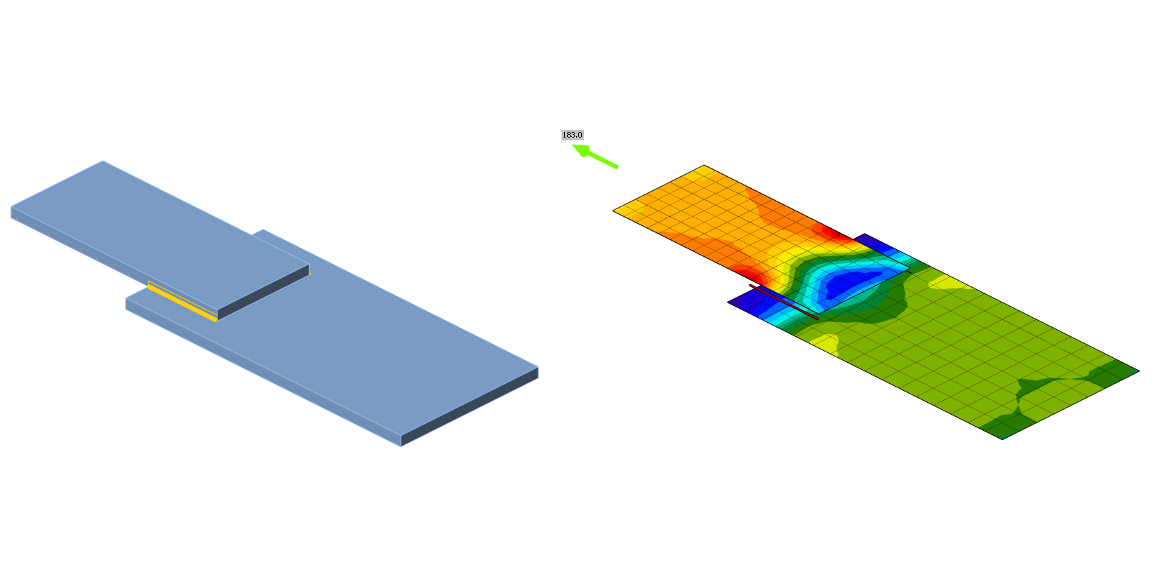
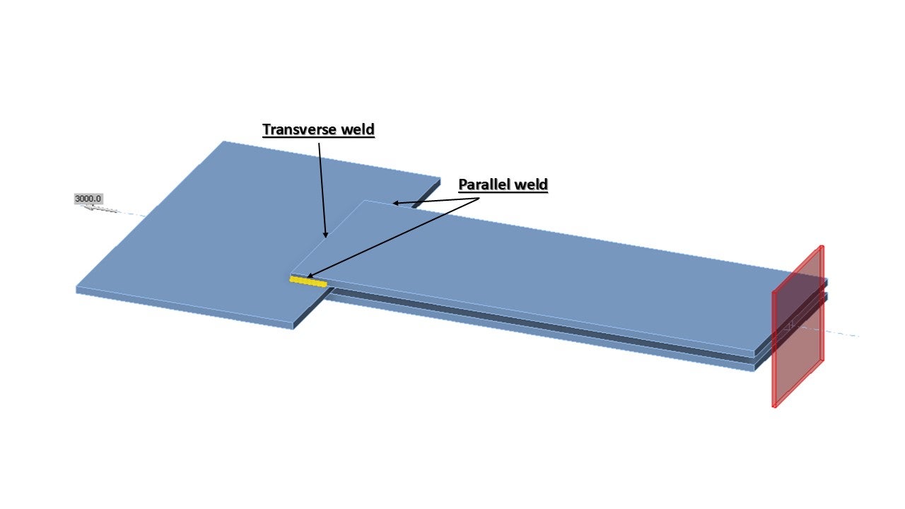
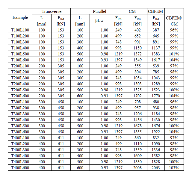
A vizsgált példák és az anyagtulajdonságok áttekintése a 4.1.1. táblázatban található. A varrat-konfigurációk: T a harántvarratra, P a párhuzamos varratra, TP a kettő kombinációjára; lásd a geometriát a 4.1.2. ábrán. Az acélminőség S235 volt (fy = 235 MPa, fu = 360 MPa, E = 210 GPa, βw = 0,8). A részleges biztonsági tényezők: γM0 = 1,0, γM2 = 1,25. A modell geometriája a 4.1.2. ábrán látható. A lemezek vastagsága 20 mm. A kapcsolat szimmetrikus, és a lemezt a hegesztett toldáskapcsolatból húzzák ki. A lemezek hosszát és szélességét a párhuzamos és harántvarrat hosszának megfelelően igazítják. A varrat teherbírása mindig a mérvadó tönkremeneteli mód. A varrat torokvastagsága 3 mm. A harántvarrat és a párhuzamos varrat hossza változó ebben a paraméteres vizsgálatban.
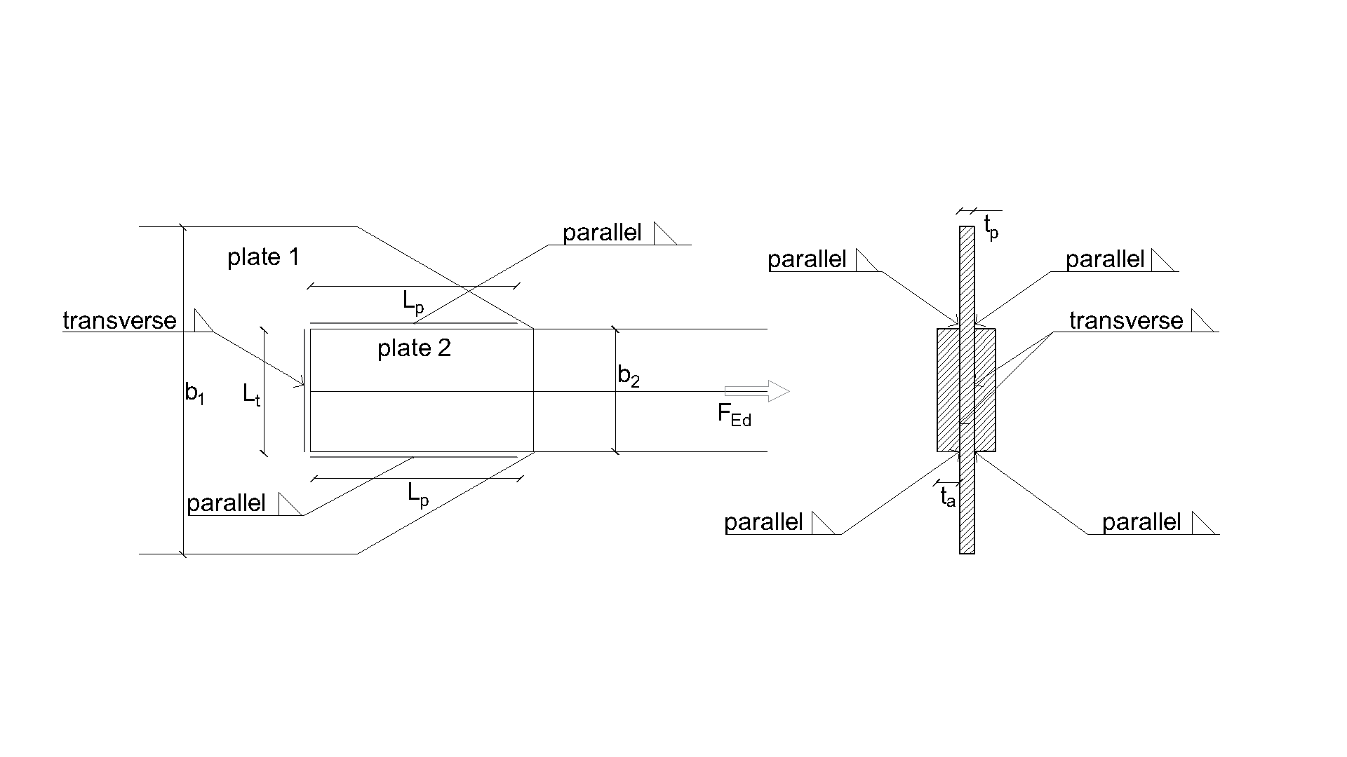
\[ \textsf{\textit{\footnotesize{Drawing 4.1 Joint geometry with dimensions}}}\]
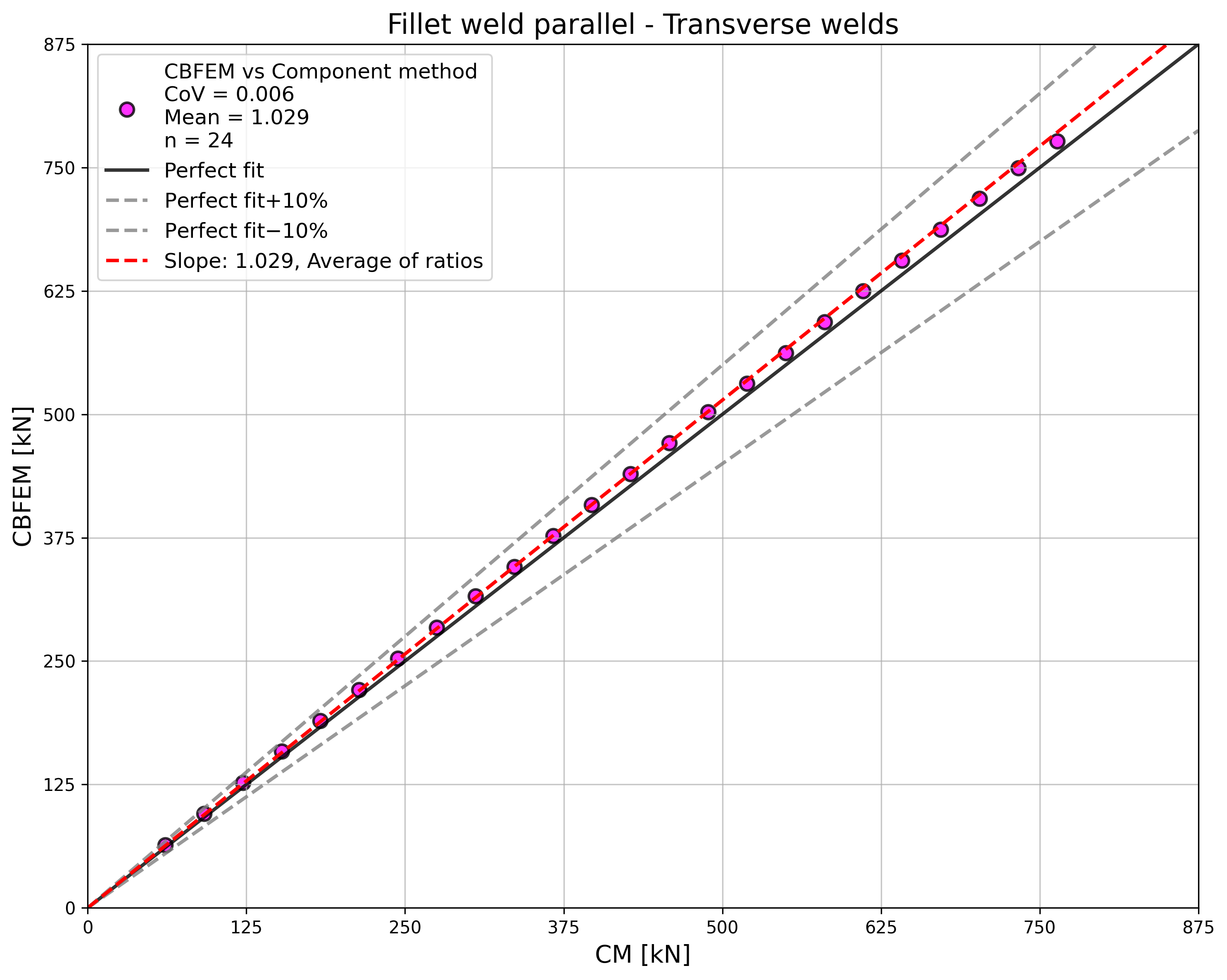
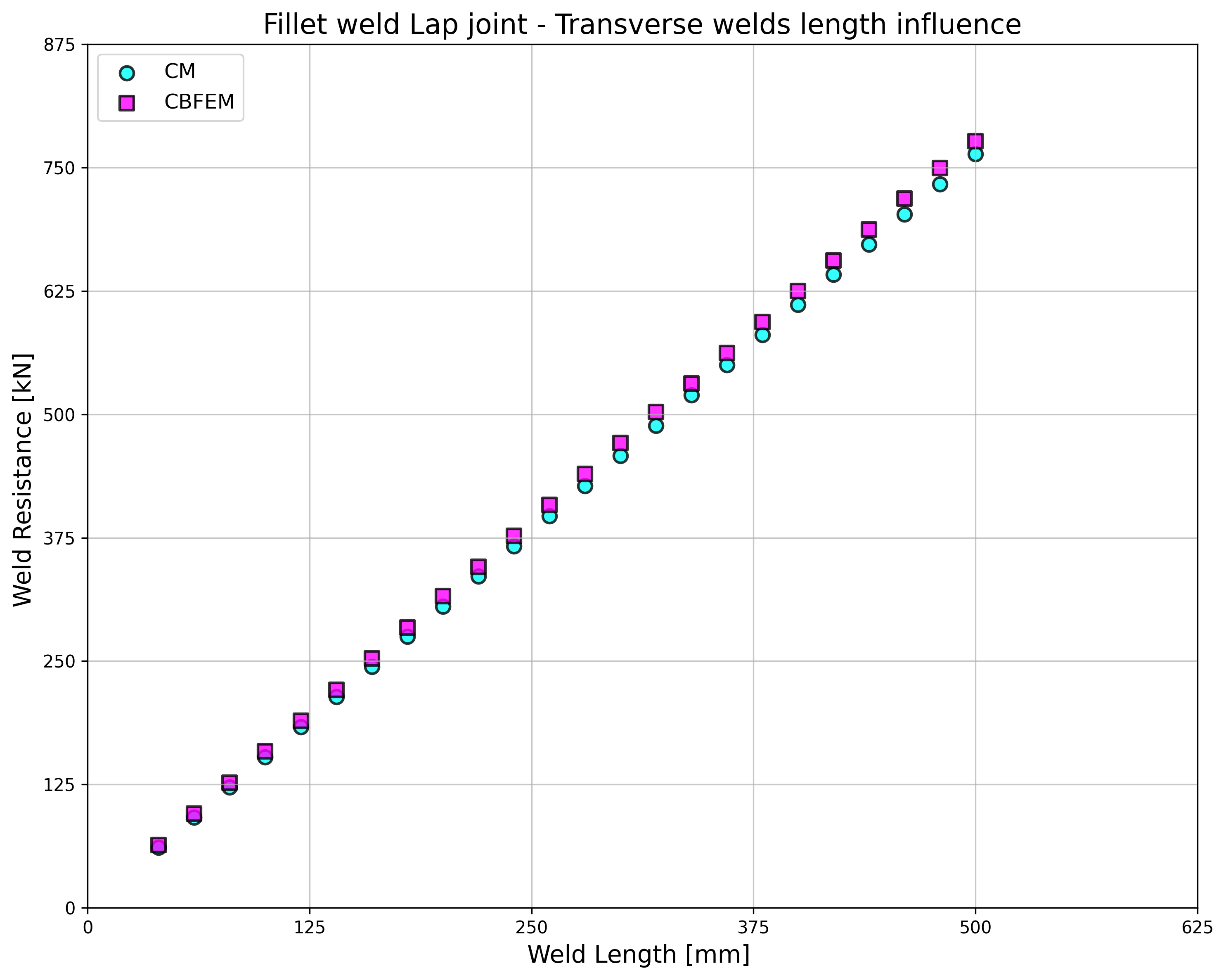
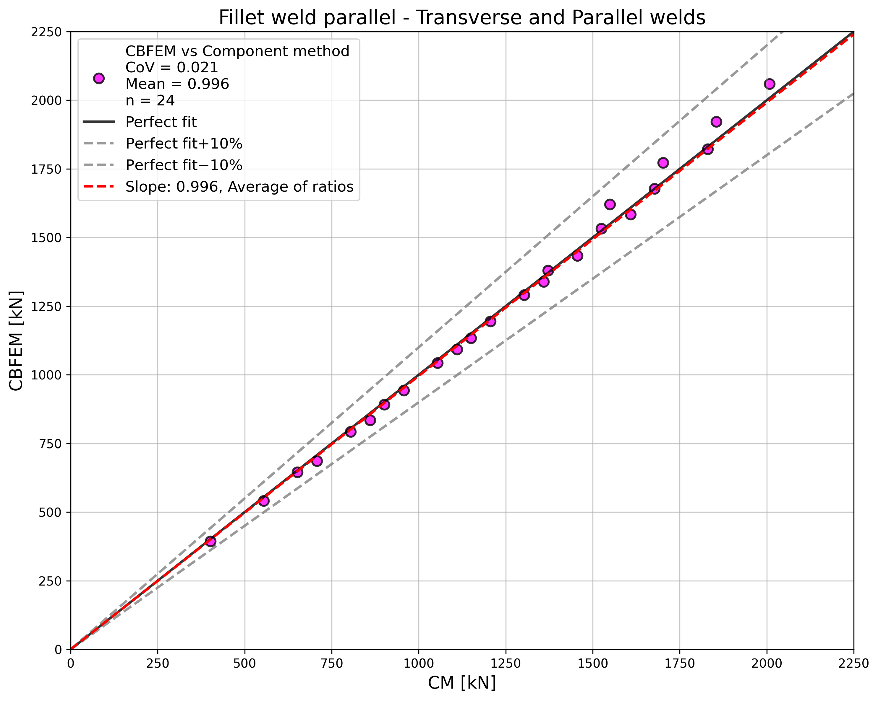
A CBFEM által számított méretezési varrat-teherbírást a CM eredményeivel hasonlítják össze. Az eredmények a 4.1.1–4.1.3. táblázatokban és a 4.1.3–4.1.5. ábrákon láthatók.
\[ \textsf{\textit{\footnotesize{Fig. 4.1.2 Specimen geometry}}}\]
Harántvarrat teherbírásának számítása
\[\sqrt{ \sigma_{\perp}^2 + 3 \cdot \left( \tau_{\perp}^2 + \tau_{\parallel}^2\right)} \leq \frac{f_\textrm{u}}{\beta_{\textrm{w}} \cdot \gamma_{\textrm{M2}}}\]
\[\sigma_{\perp} = \tau_{\perp} = \frac{\sigma_\textrm{N}}{\sqrt{2}} = \frac{N}{L_{\textrm{t}} \cdot a}\cdot \frac{1}{\sqrt{2}} \]
\[ \tau_{\parallel} = 0\]
\[ \sqrt{ \left( \frac{\sigma_\textrm{N}}{\sqrt{2}} \right)^2 + 3 \cdot \left( \frac{\sigma_\textrm{N}}{\sqrt{2}} \right)^2} \leq \frac{f_\textrm{u}}{\beta_{\textrm{w}} \cdot \gamma_{\textrm{M2}}}\]
\[ \sqrt{ \left( \frac{N}{L_{\textrm{t}}\cdot a}\cdot \frac{1}{\sqrt{2}} \right)^2 + 3 \cdot \left( \frac{N}{L_{\textrm{t}}\cdot a}\cdot \frac{1}{\sqrt{2}} \right)^2} \leq \frac{f_\textrm{u}}{\beta_{\textrm{w}} \cdot \gamma_{\textrm{M2}}}\]
\[ N \leq \frac{f_\textrm{u} \cdot L_{\textrm{t}}\cdot a }{\beta_{\textrm{w}} \cdot \gamma_{\textrm{M2}} \cdot \sqrt{2}} \]
\[ \sigma_{\perp}= \frac{N}{L_{\textrm{t}} \cdot a}\cdot \frac{1}{\sqrt{2}} \leq \frac{f_\textrm{u} \cdot 0.9}{ \gamma_{\textrm{M2}}} \]
\[ N \leq \frac{f_{u} \cdot L_{\textrm{t}}\cdot a \cdot 0.9 \cdot \sqrt{2}}{ \gamma_{\textrm{M2}} } \]
Ahol:
\(a\) - varrat torokvastagsága
\(N\) - a szerkezeti elemen ható normálerő
\(L_{\textrm{t}}\) - harántvarrat teljes hossza
\(\beta_{\mathrm{w}}\) - korrelációs tényező az EN 1993-1-8 4.1. táblázatából
\(f_\textrm{u}\) - az összekapcsolt gyengébb rész névleges szakítószilárdsága
\(\gamma_{\mathrm{M2}}\) - varratokra vonatkozó részleges biztonsági tényező
Párhuzamos varrat teherbírásának számítása
\[\sqrt{ \sigma_{\perp}^2 + 3 \cdot \left( \tau_{\perp}^2 + \tau_{\parallel}^2\right)} \leq \frac{f_\textrm{u}}{\beta_{\mathrm{w}} \cdot \gamma_{\mathrm{M2}}}\]
\[\sigma_{\perp} = \tau_{\perp} = 0 \]
\[ \tau_{\parallel} = \frac{V}{L_{\textrm{p}} \cdot a}\]
\[ \sqrt{ 3 \cdot \left( \tau_{\parallel} \right)^2} \leq \frac{f_\textrm{u}}{\beta_{\mathrm{w}} \cdot \gamma_{\mathrm{M2}}}\]
\[ \sqrt{ 3 \cdot \left( \frac{V}{L_{\textrm{p}} \cdot a}\right)^2} \leq \frac{f_\textrm{u}}{\beta_{\mathrm{w}} \cdot \gamma_{\mathrm{M2}}}\]
\[ V = \frac{f_\textrm{u} \cdot L_{\textrm{p}} \cdot a \cdot \beta_{\mathrm{Lw1}}}{\beta_{\mathrm{w}} \cdot \gamma_{\mathrm{M2}} \cdot \sqrt{3}} \]
Ahol:
\(a\) - varrat torokvastagsága
\(V\) - a szerkezeti elemen ható nyíróerő
\(L_{\textrm{t}}\) - párhuzamos varrat teljes hossza
\(\beta_{\mathrm{w}}\) - korrelációs tényező az EN 1993-1-8 4.1. táblázatából
\(\beta_{\mathrm{Lw1}}\) - hosszú varrat csökkentési tényezője, EN 1993-1-8 4.9. képlet
\(f_\textrm{u}\) - az összekapcsolt gyengébb rész névleges szakítószilárdsága
\(\gamma_{\mathrm{M2}}\) - varratokra vonatkozó részleges biztonsági tényező
Harántvarrat és párhuzamos varrat kombinált számítása
A harántvarrat és párhuzamos varrat kombinációjára kézzel számított teherbírás egyszerűen a fenti egyenletekből levezetett harántvarrat- és párhuzamos varrat-teherbírások összege.
Eredmények bemutatása
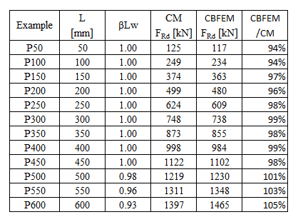
\[ \textsf{\textit{\footnotesize{Tab. 4.1.1 Parallel welds results}}}\]
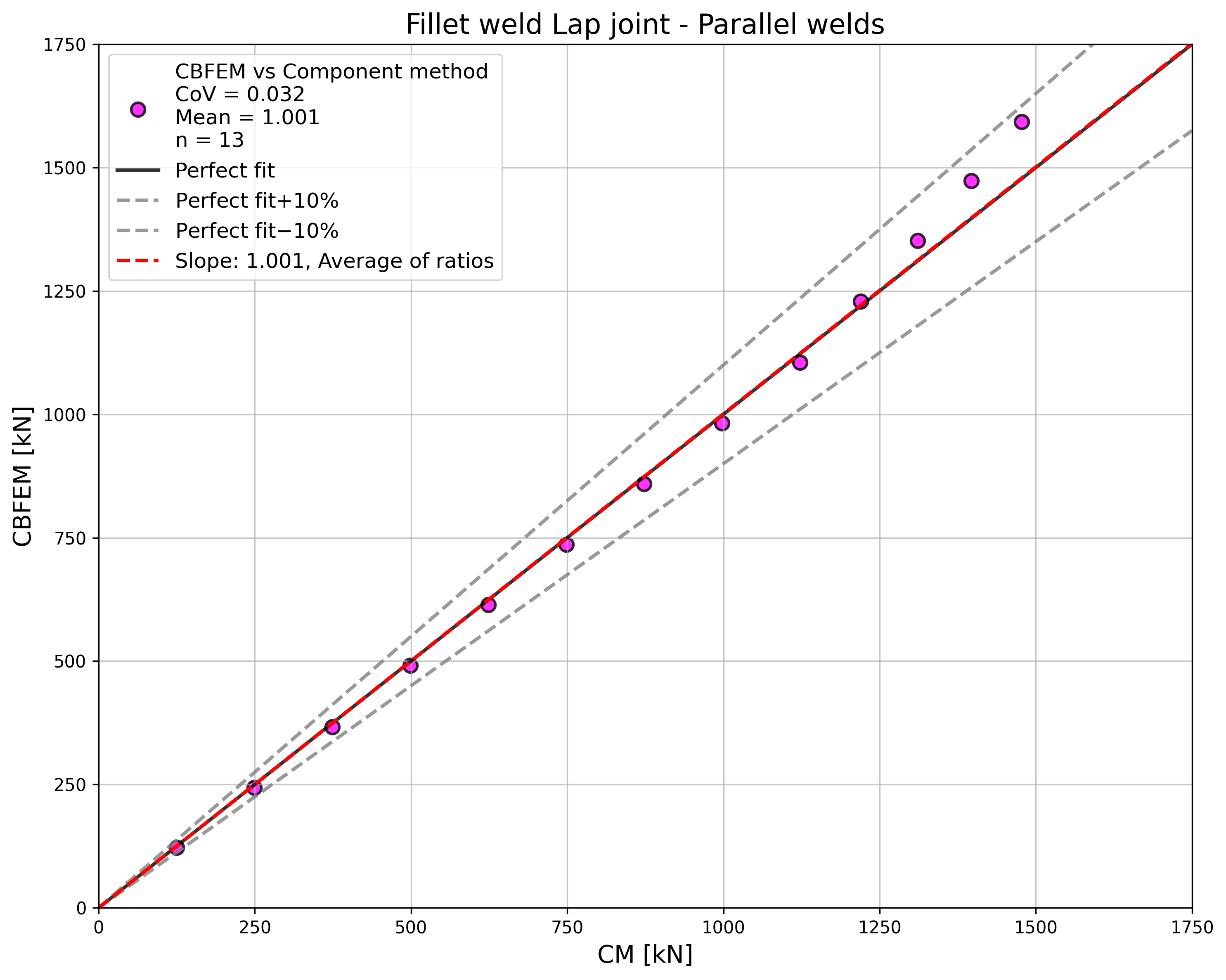
\[ \textsf{\textit{\footnotesize{Fig. 4.1.3 Comparison of load resistances of parallel welds}}}\]
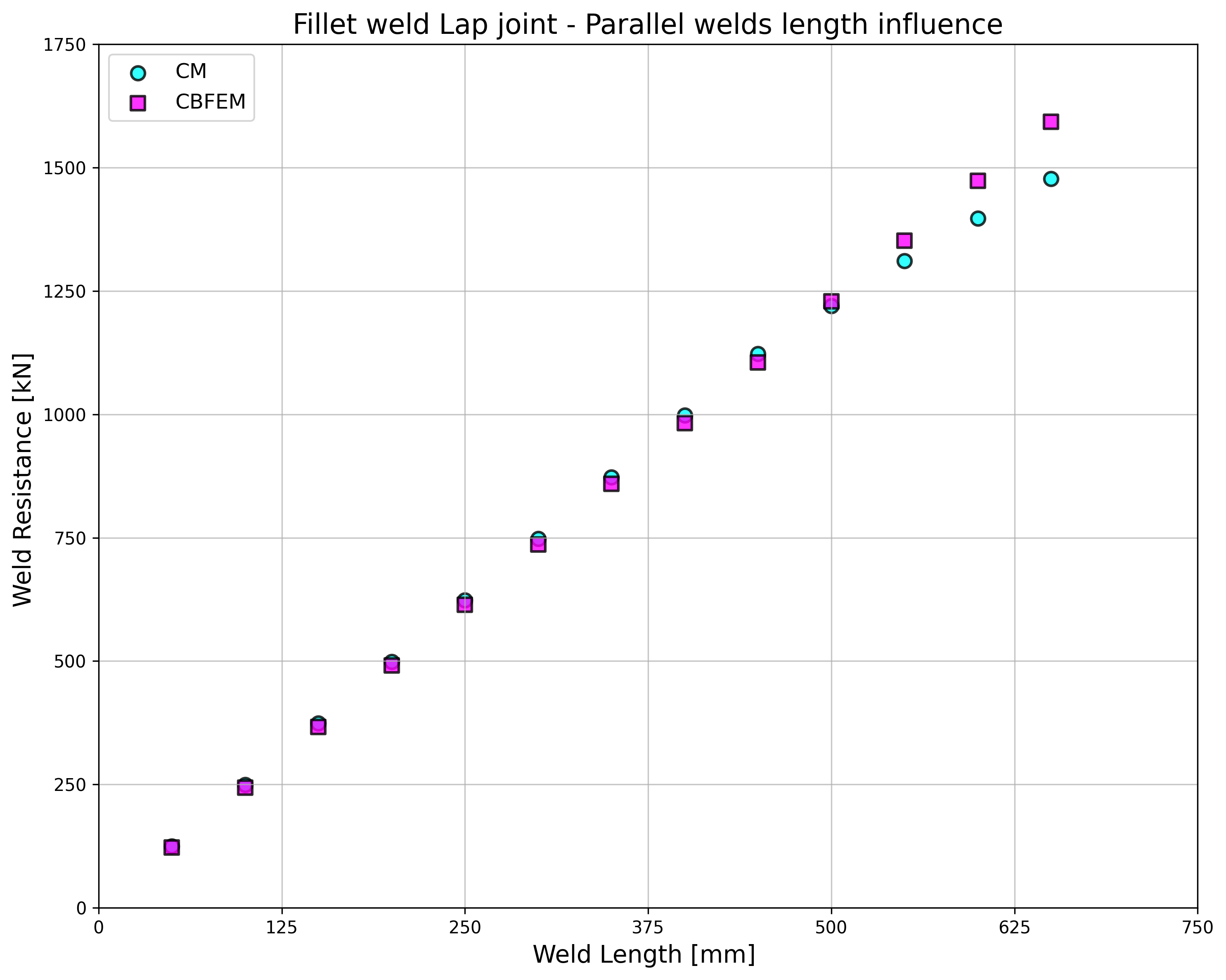
\[ \textsf{\textit{\footnotesize{Fig. 4.1.3.a Influence of weld length on resistance}}}\]
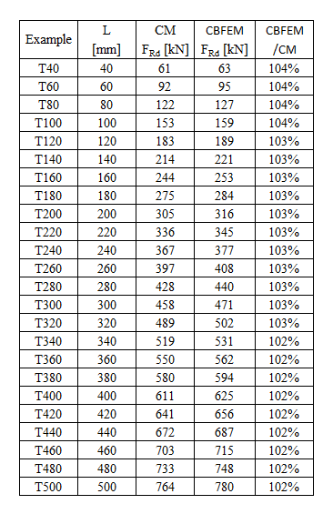
\[ \textsf{\textit{\footnotesize{Tab. 4.1.2 Transverse welds}}}\]
\[ \textsf{\textit{\footnotesize{Fig. 4.1.4 Comparison of load resistances of transverse welds}}}\]
\[ \textsf{\textit{\footnotesize{Fig. 4.1.4.a Influence of weld length on resistance}}}\]
\[ \textsf{\textit{\footnotesize{Tab. 4.1.3 Grouped welds}}}\]
\[ \textsf{\textit{\footnotesize{Fig. 4.1.5 Comparison of load resistances of group}}}\]
A párhuzamos varrat, a harántvarrat és a vegyes irányú varratcsoportok teherbírása a CM és a CBFEM szerint közel azonos. A tanulmányban a legnagyobb eltérés a teherbírásban 6%.
A párhuzamos varratokra vonatkozó CBFEM-eredmények kissé konzervatívak, de hosszú varratok esetén kezdenek eltérni. A hosszú varratokból adódó teherbírás-csökkentést a CBFEM nem veszi figyelembe, azonban nem várható, hogy 200×torokvastagságnál hosszabb varrat előforduljon bármely kapcsolatban, és ezen hosszig az eredmények még nagyon közel vannak egymáshoz.
Harántvarratoknál a CBFEM nagyon következetes eredményeket ad, 2–4%-kal magasabb teherbírással.
Benchmark példa
Bemeneti adatok
1. szerkezeti elem – Iw60x500
• Lemezekből hegesztve, vastagsággal t = 20 mm
• Szélesség b = 500 mm
• A gerinc eltávolítva Nyílás gyártási művelettel
• S235 acél
2. szerkezeti elem – Lemez 20x1000
• Vastagság t = 20 mm
• Szélesség b = 1000 mm
• S235 acél
• Eltolás ex = –90 mm
Harántirányú sarokvarrat a 2. szerkezeti elem mindkét oldalán
• Torokvastagság a = 3 mm
• Varrat hossza Lt = 100 mm
Párhuzamos sarokvarrat a 2. szerkezeti elem mindkét oldalán
• Torokvastagság a = 3 mm
• Varrat hossza Lp = 100 mm
Eredmény
• Méretezési húzási teherbírás FRd = 387 kN (Megjegyzendő, hogy a teherbírást a „Megállás határalakváltozásnál" funkció alkalmazásával számították. Következésképpen a tényleges CBFEM-teherbírás marginálisan magasabb lehet.)