Soldadura de filete em junta sobreposta
Descrição
O objetivo deste capítulo é a verificação do método dos elementos finitos baseado em componentes (CBFEM) de uma soldadura de filete numa junta sobreposta com o método das componentes (CM). Duas chapas são ligadas em três configurações, nomeadamente com uma soldadura transversal, com uma soldadura longitudinal e uma combinação de soldaduras transversais e longitudinais. O comprimento e a espessura de garganta da soldadura são os parâmetros variáveis no estudo. O estudo abrange também soldaduras longas cuja resistência é reduzida devido à concentração de tensões. A junta é carregada por uma força normal.
Modelo analítico
A soldadura de filete é o único componente examinado no estudo. As soldaduras são dimensionadas para serem o componente mais fraco da junta. A soldadura é dimensionada de acordo com EN 1993-1-8:2005. A resistência de cálculo da soldadura de filete é determinada utilizando o método direcional indicado na Cl. 4.5.3.2 da EN 1993-1-8:2005. Os métodos de cálculo disponíveis para verificar a resistência das soldaduras de filete baseiam-se na hipótese simplificadora de que as tensões são uniformemente distribuídas na secção de garganta de uma soldadura de filete, conduzindo às tensões normais e tensões de corte apresentadas na Fig. 4.1.1, como se segue:
- σ⊥ é a tensão normal perpendicular à secção de garganta;
- σ∥ é a tensão normal paralela ao eixo da soldadura na sua secção transversal;
- τ⊥ é a tensão de corte (no plano da secção de garganta) perpendicular ao eixo da soldadura;
- τ∥ é a tensão de corte (no plano da secção de garganta) paralela ao eixo da soldadura.
A tensão normal σ∥ paralela ao eixo não é considerada na verificação da resistência de cálculo de uma soldadura.
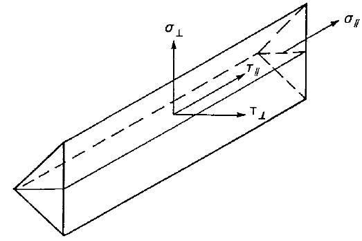
\[ \textsf{\textit{\footnotesize{Fig. 4.1.1 Stresses in a throat section of a fillet weld}}}\]
A resistência de cálculo da soldadura de filete será suficiente se ambas as seguintes condições forem satisfeitas:
\[ \sqrt{\sigma_{\perp}^2 + 3 \cdot ( \tau_{\perp}^2 + \tau_{\perp}^2 )} \le \frac{f_\textrm{u}}{\beta_\textrm{w} \gamma_\textrm{M2}} \]
\[ \sigma_{\perp} \le \frac{0.9 f_\textrm{u}}{\gamma_\textrm{M2}} \]
Em juntas sobrepostas com comprimento superior a \( 150 \cdot a \), o fator de redução \(\beta_{\mathrm{Lw,1}}\) é dado por:
\( \beta_{\mathrm{Lw,1}} = 1.2 - \frac{0.2 L_\textrm{j}}{150 a} \) mas \(\beta_{\mathrm{Lw,1}} \le 1.0 \)
Modelo numérico
O componente de soldadura no CBFEM é descrito em Fundamentos teóricos gerais e Fundamentos teóricos EN. É utilizado material elasto-plástico não linear para as soldaduras neste estudo. A deformação plástica limite é atingida na parte mais longa da soldadura, e os picos de tensão são redistribuídos.
Verificação da resistência
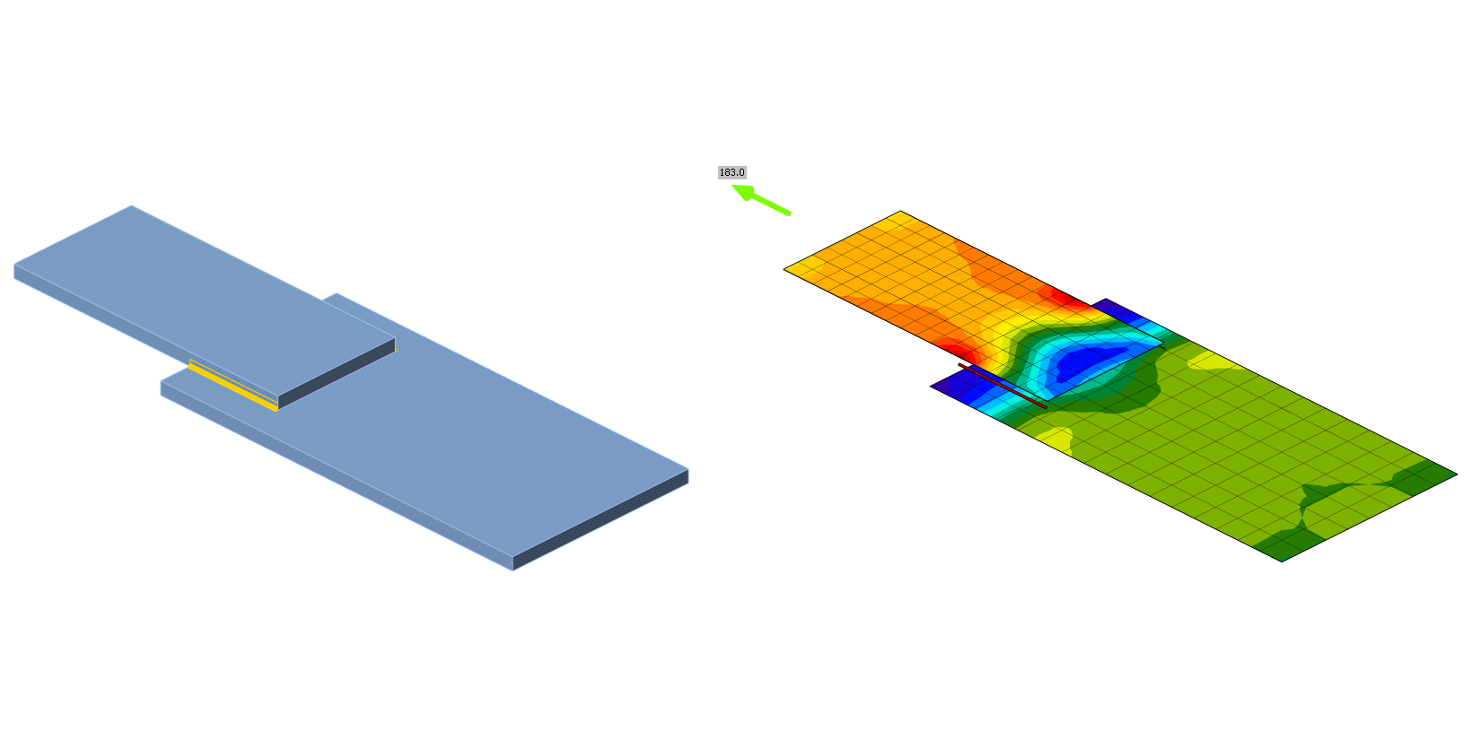
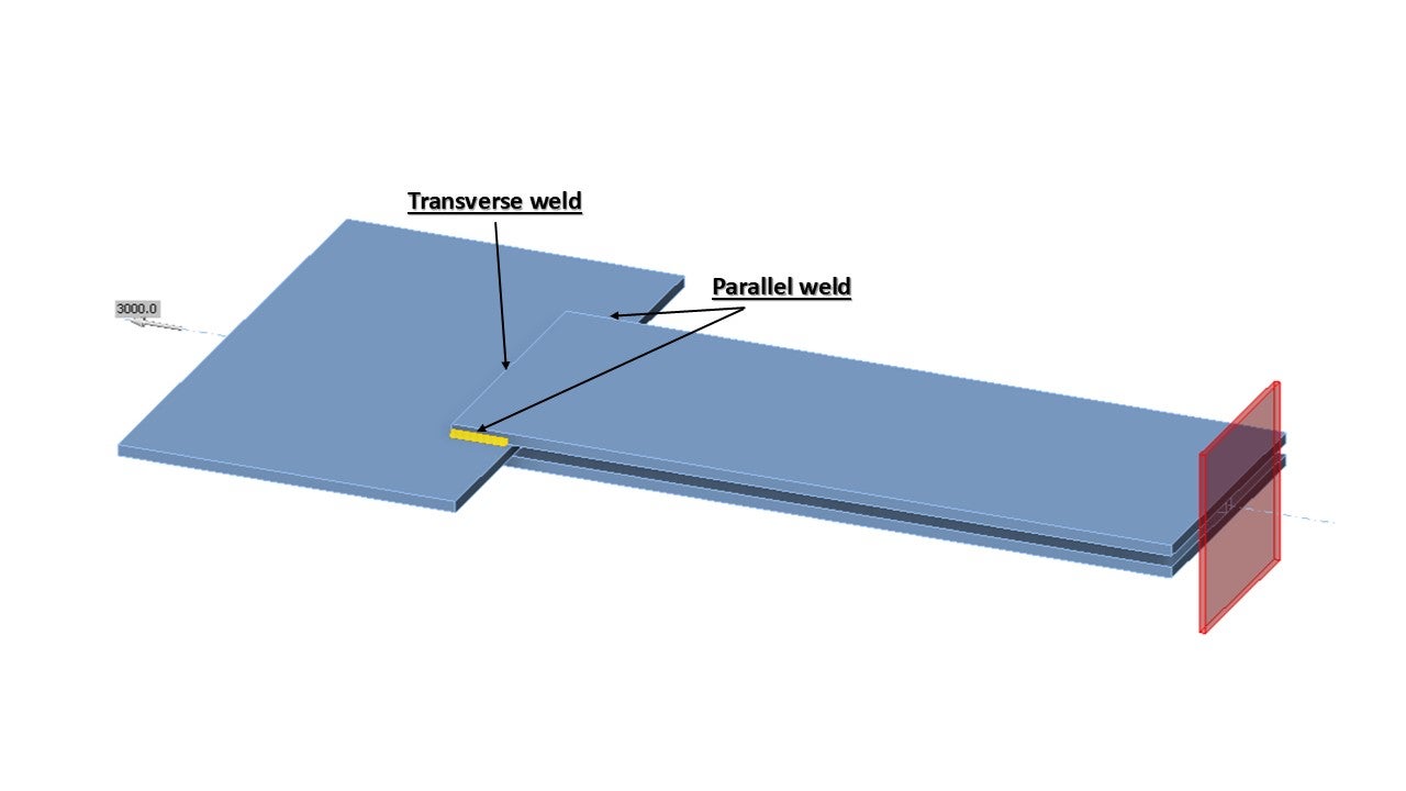
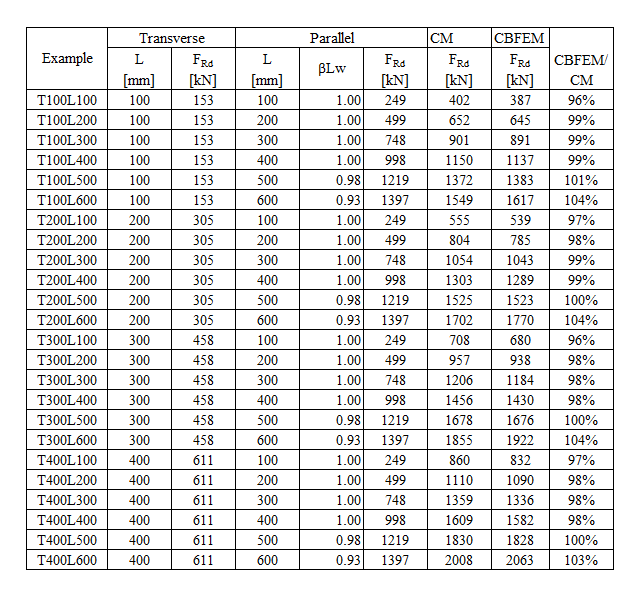
Uma visão geral dos exemplos considerados e das propriedades dos materiais é apresentada no Tab. 4.1.1. As configurações de soldadura são T para transversal, P para soldadura paralela e TP para uma combinação de ambas; ver a geometria na Fig. 4.1.2. O aço utilizado foi S235 (fy = 235 MPa, fu = 360 MPa, E = 210 GPa, βw = 0,8). Os coeficientes parciais de segurança foram γM0 = 1,0, γM2 = 1,25. A geometria do modelo é apresentada na Fig. 4.1.2. As chapas têm uma espessura de 20 mm. A ligação é simétrica e a chapa é tracionada para fora da ligação de emenda soldada. O comprimento e a largura das chapas são ajustados de acordo com o comprimento da soldadura paralela e transversal. A resistência da soldadura é sempre o modo de rotura condicionante. A espessura de garganta da soldadura é de 3 mm. Os comprimentos das soldaduras transversais e paralelas variam neste estudo paramétrico.
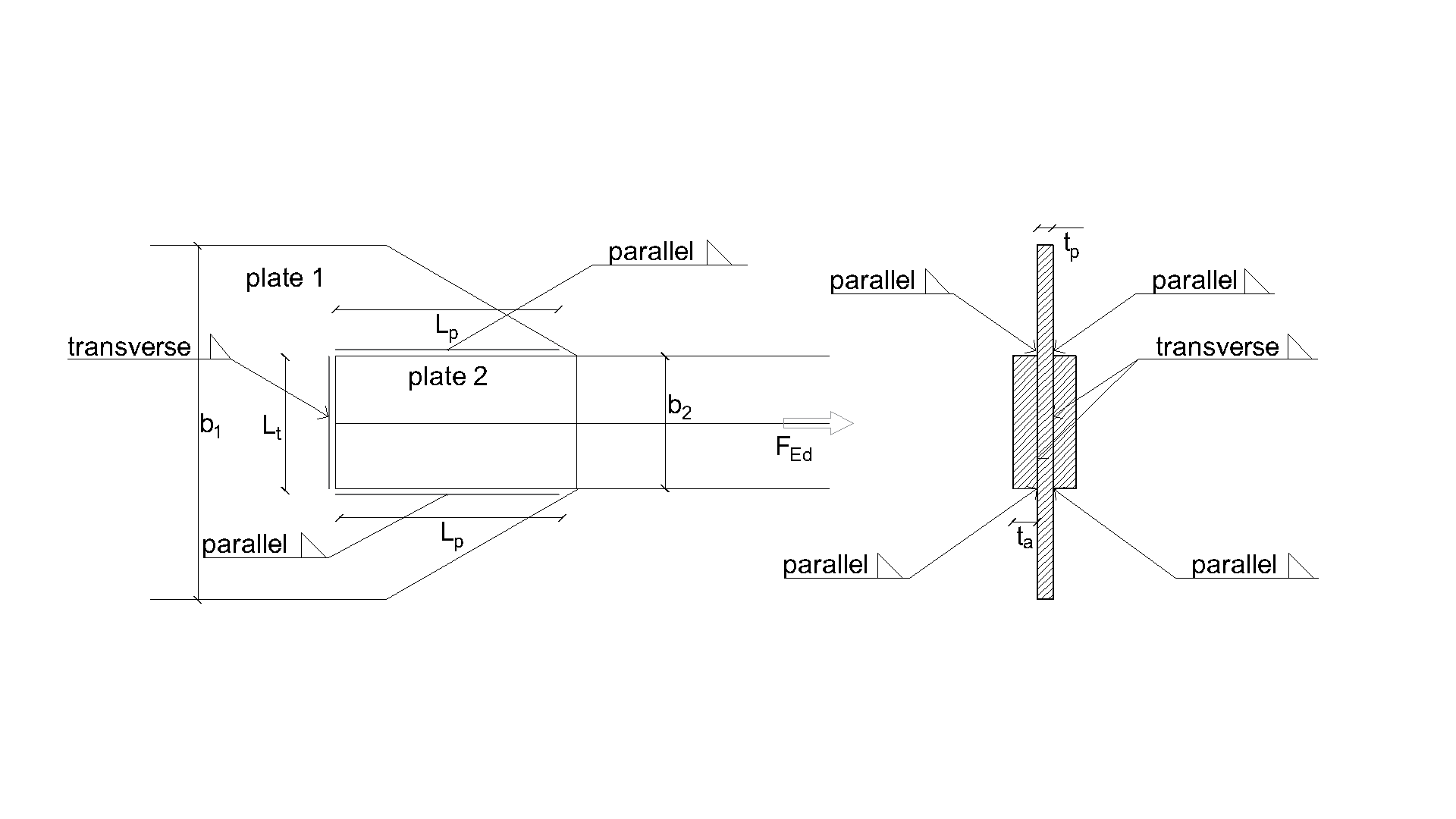
\[ \textsf{\textit{\footnotesize{Drawing 4.1 Joint geometry with dimensions}}}\]
A resistência de cálculo da soldadura calculada pelo CBFEM é comparada com os resultados do CM. Os resultados são apresentados no Tab. 4.1.1 – 4.1.3 e Fig. 4.1.3 – 4.1.5.
\[ \textsf{\textit{\footnotesize{Fig. 4.1.2 Specimen geometry}}}\]
Cálculo da resistência de soldaduras transversais
\[\sqrt{ \sigma_{\perp}^2 + 3 \cdot \left( \tau_{\perp}^2 + \tau_{\parallel}^2\right)} \leq \frac{f_\textrm{u}}{\beta_{\textrm{w}} \cdot \gamma_{\textrm{M2}}}\]
\[\sigma_{\perp} = \tau_{\perp} = \frac{\sigma_\textrm{N}}{\sqrt{2}} = \frac{N}{L_{\textrm{t}} \cdot a}\cdot \frac{1}{\sqrt{2}} \]
\[ \tau_{\parallel} = 0\]
\[ \sqrt{ \left( \frac{\sigma_\textrm{N}}{\sqrt{2}} \right)^2 + 3 \cdot \left( \frac{\sigma_\textrm{N}}{\sqrt{2}} \right)^2} \leq \frac{f_\textrm{u}}{\beta_{\textrm{w}} \cdot \gamma_{\textrm{M2}}}\]
\[ \sqrt{ \left( \frac{N}{L_{\textrm{t}}\cdot a}\cdot \frac{1}{\sqrt{2}} \right)^2 + 3 \cdot \left( \frac{N}{L_{\textrm{t}}\cdot a}\cdot \frac{1}{\sqrt{2}} \right)^2} \leq \frac{f_\textrm{u}}{\beta_{\textrm{w}} \cdot \gamma_{\textrm{M2}}}\]
\[ N \leq \frac{f_\textrm{u} \cdot L_{\textrm{t}}\cdot a }{\beta_{\textrm{w}} \cdot \gamma_{\textrm{M2}} \cdot \sqrt{2}} \]
\[ \sigma_{\perp}= \frac{N}{L_{\textrm{t}} \cdot a}\cdot \frac{1}{\sqrt{2}} \leq \frac{f_\textrm{u} \cdot 0.9}{ \gamma_{\textrm{M2}}} \]
\[ N \leq \frac{f_{u} \cdot L_{\textrm{t}}\cdot a \cdot 0.9 \cdot \sqrt{2}}{ \gamma_{\textrm{M2}} } \]
Onde:
\(a\) - espessura de garganta da soldadura
\(N\) - força normal atuante no elemento
\(L_{\textrm{t}}\) - comprimento total da soldadura transversal
\(\beta_{\mathrm{w}}\) - fator de correlação retirado da Tabela 4.1 da EN 1993-1-8
\(f_\textrm{u}\) - resistência última à tração nominal da parte mais fraca ligada
\(\gamma_{\mathrm{M2}}\) - coeficiente parcial de segurança para soldaduras
Cálculo da resistência de soldaduras paralelas
\[\sqrt{ \sigma_{\perp}^2 + 3 \cdot \left( \tau_{\perp}^2 + \tau_{\parallel}^2\right)} \leq \frac{f_\textrm{u}}{\beta_{\mathrm{w}} \cdot \gamma_{\mathrm{M2}}}\]
\[\sigma_{\perp} = \tau_{\perp} = 0 \]
\[ \tau_{\parallel} = \frac{V}{L_{\textrm{p}} \cdot a}\]
\[ \sqrt{ 3 \cdot \left( \tau_{\parallel} \right)^2} \leq \frac{f_\textrm{u}}{\beta_{\mathrm{w}} \cdot \gamma_{\mathrm{M2}}}\]
\[ \sqrt{ 3 \cdot \left( \frac{V}{L_{\textrm{p}} \cdot a}\right)^2} \leq \frac{f_\textrm{u}}{\beta_{\mathrm{w}} \cdot \gamma_{\mathrm{M2}}}\]
\[ V = \frac{f_\textrm{u} \cdot L_{\textrm{p}} \cdot a \cdot \beta_{\mathrm{Lw1}}}{\beta_{\mathrm{w}} \cdot \gamma_{\mathrm{M2}} \cdot \sqrt{3}} \]
Onde:
\(a\) - espessura de garganta da soldadura
\(V\) - força de corte atuante no elemento
\(L_{\textrm{t}}\) - comprimento total das soldaduras paralelas
\(\beta_{\mathrm{w}}\) - fator de correlação retirado da Tabela 4.1 da EN 1993-1-8
\(\beta_{\mathrm{Lw1}}\) - fator de redução para soldaduras longas, Equação 4.9 da EN 1993-1-8
\(f_\textrm{u}\) - resistência última à tração nominal da parte mais fraca ligada
\(\gamma_{\mathrm{M2}}\) - coeficiente parcial de segurança para soldaduras
Cálculo de soldaduras transversais e paralelas
A resistência calculada manualmente para uma combinação de soldadura transversal e paralela é simplesmente a soma das resistências transversal e paralela derivadas das equações acima.
Apresentação de resultados
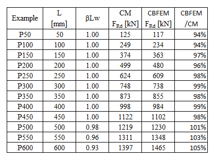
\[ \textsf{\textit{\footnotesize{Tab. 4.1.1 Parallel welds results}}}\]
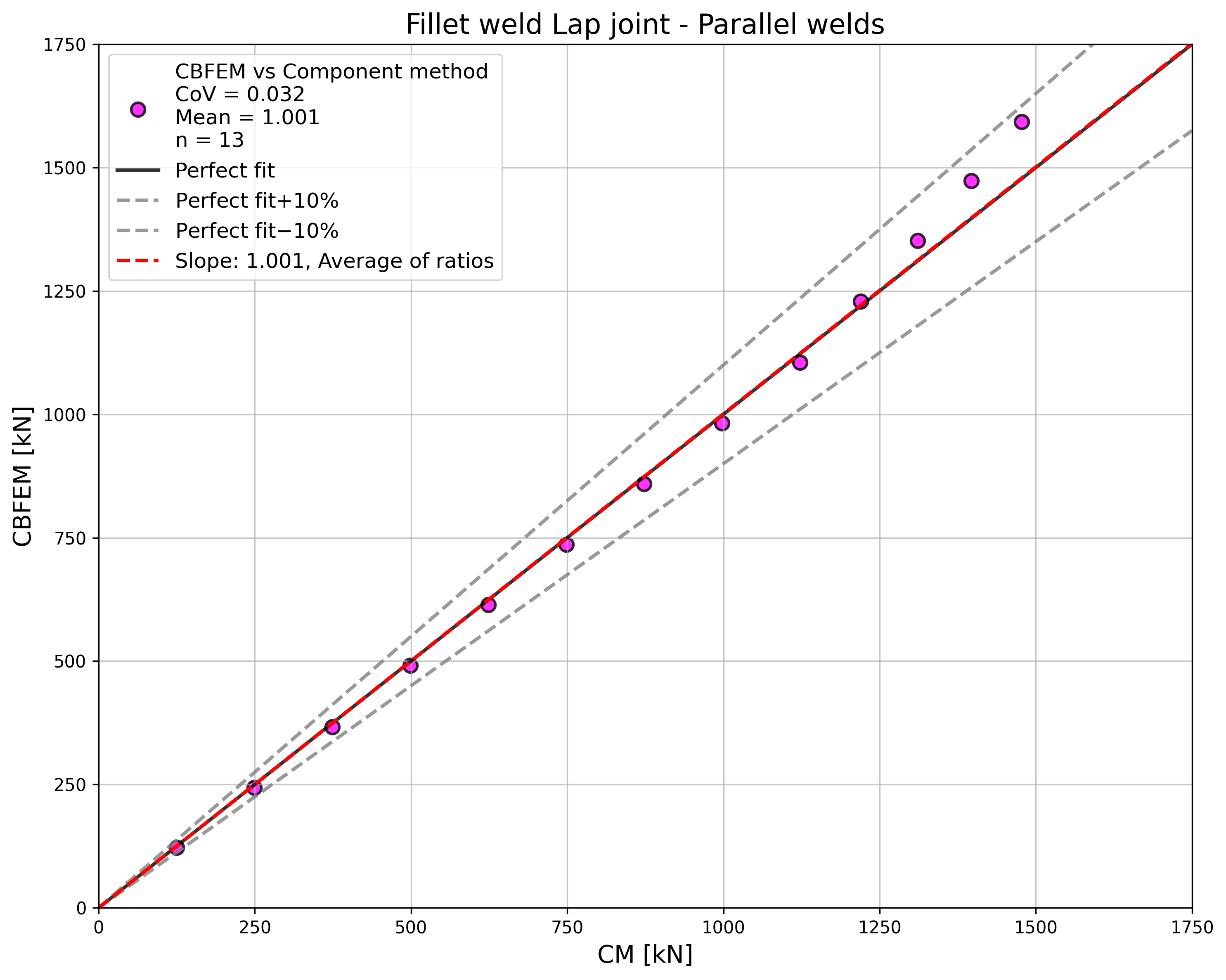
\[ \textsf{\textit{\footnotesize{Fig. 4.1.3 Comparison of load resistances of parallel welds}}}\]
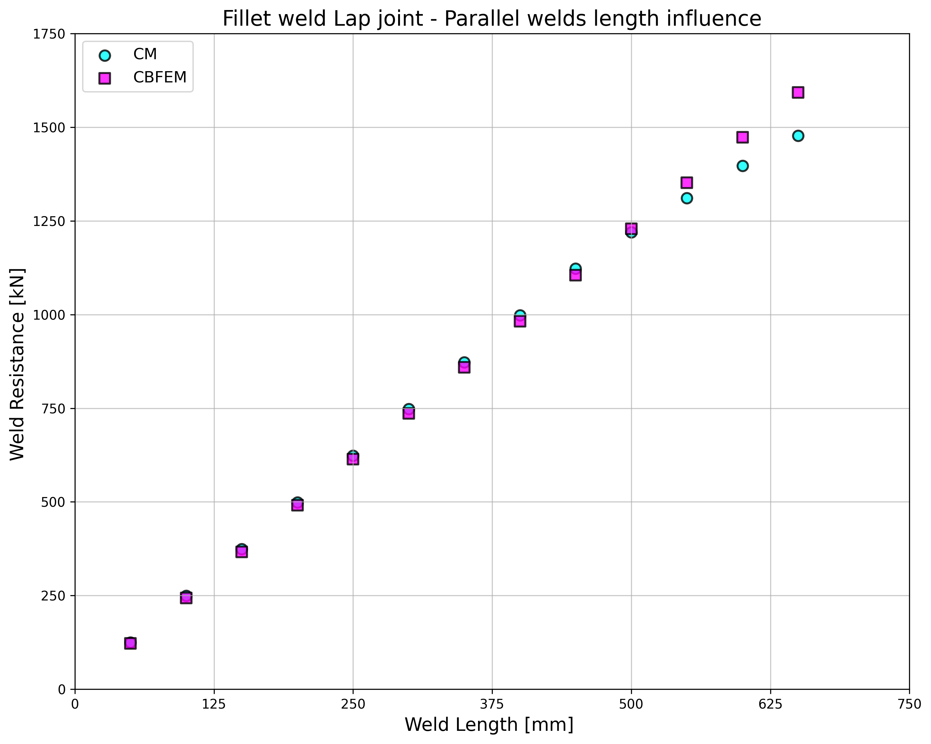
\[ \textsf{\textit{\footnotesize{Fig. 4.1.3.a Influence of weld length on resistance}}}\]
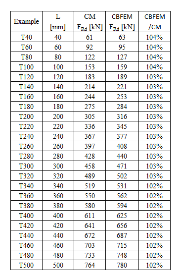
\[ \textsf{\textit{\footnotesize{Tab. 4.1.2 Transverse welds}}}\]
\[ \textsf{\textit{\footnotesize{Fig. 4.1.4 Comparison of load resistances of transverse welds}}}\]
\[ \textsf{\textit{\footnotesize{Fig. 4.1.4.a Influence of weld length on resistance}}}\]
\[ \textsf{\textit{\footnotesize{Tab. 4.1.3 Grouped welds}}}\]
\[ \textsf{\textit{\footnotesize{Fig. 4.1.5 Comparison of load resistances of group}}}\]
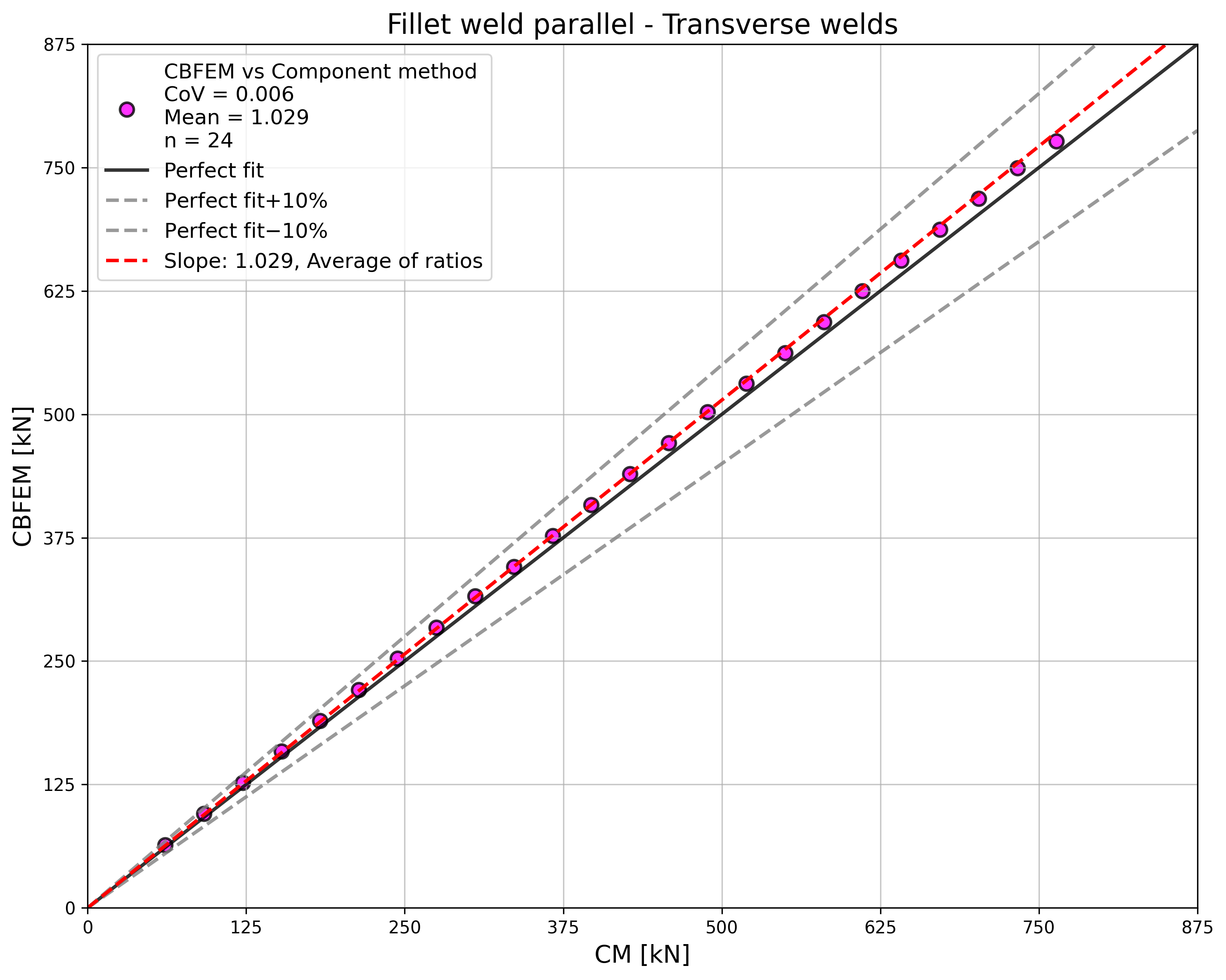
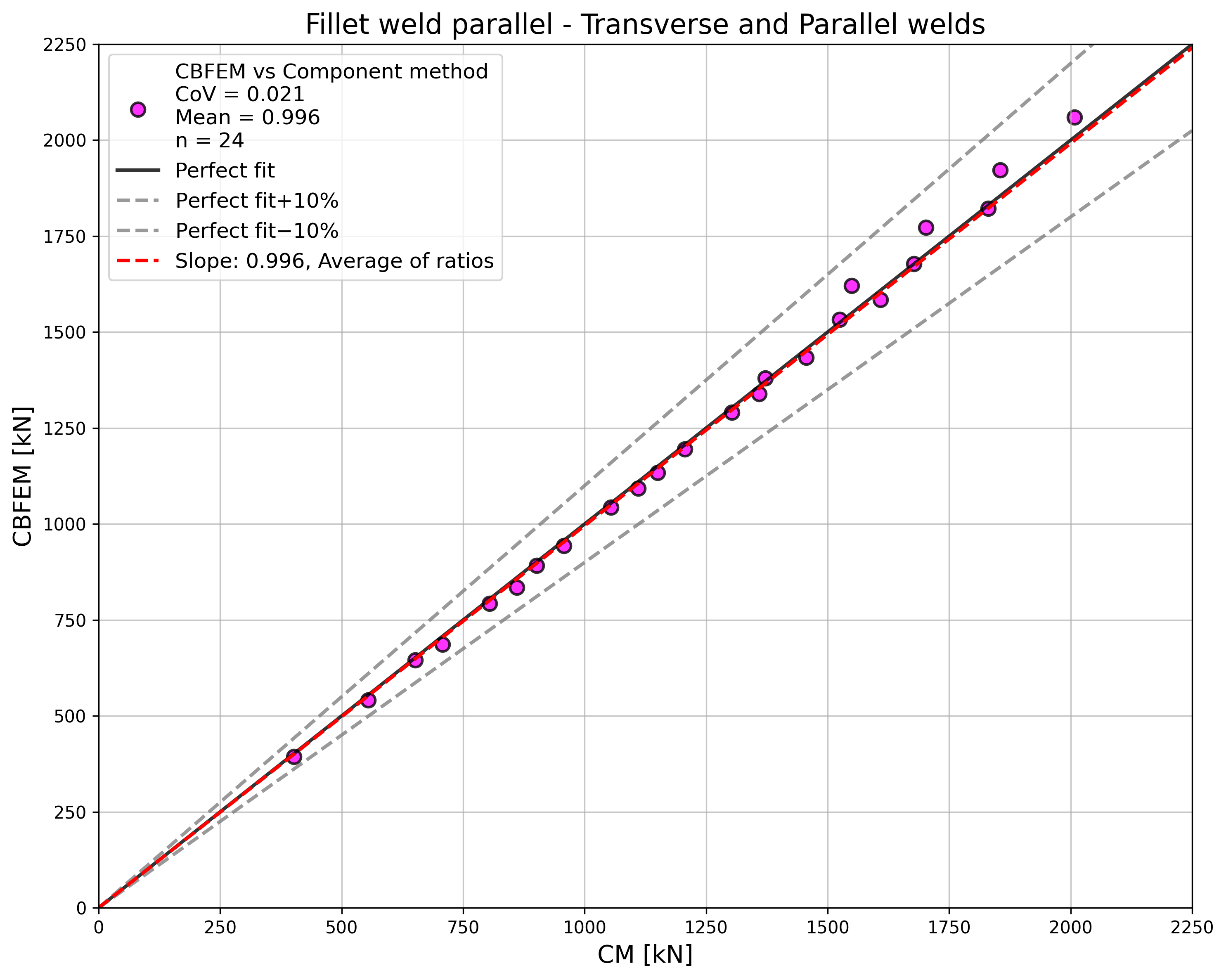
A resistência das soldaduras paralelas, soldaduras transversais e grupos de soldaduras multi-orientadas é praticamente idêntica de acordo com o CM e o CBFEM. A maior diferença neste estudo é de 6% na resistência de carga.
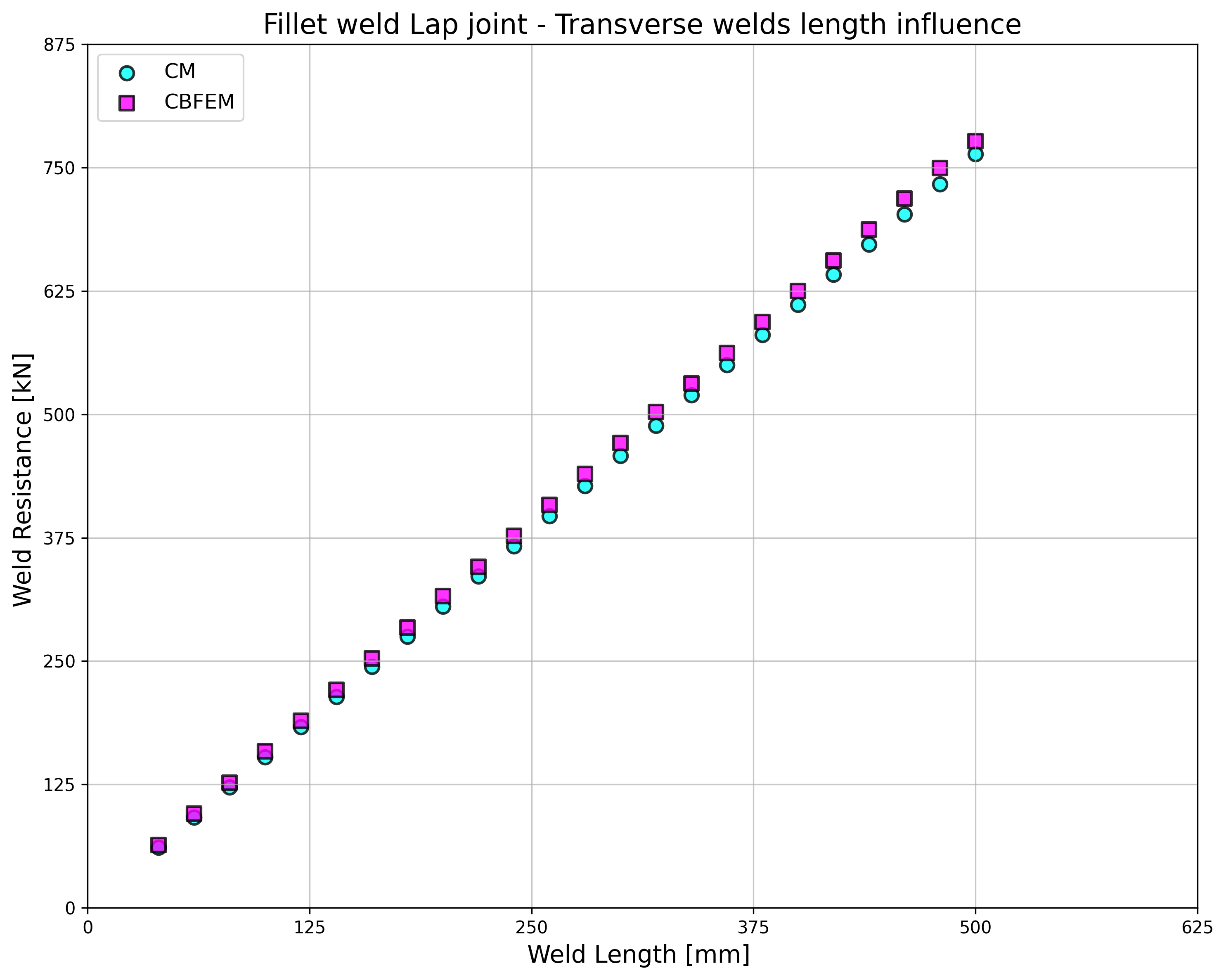
Os resultados do CBFEM para soldaduras paralelas são ligeiramente conservadores, mas começam a divergir para soldaduras longas. A redução da resistência devida a soldaduras longas não é captada pelo CBFEM, mas não é expectável que soldaduras com comprimento superior a 200 vezes a espessura de garganta possam aparecer em qualquer ligação, e até este comprimento os resultados são ainda muito próximos.
Para soldaduras transversais, o CBFEM fornece resultados muito consistentes com uma resistência 2–4% superior.
Exemplo de referência
Dados de entrada
Elemento 1 – Iw60x500
• Soldado a partir de chapas com espessura t = 20 mm
• Largura b = 500 mm
• A alma é removida pela operação de fabrico de abertura
• Aço S235
Elemento 2 – Chapa 20x1000
• Espessura t = 20 mm
• Largura b = 1000 mm
• Aço S235
• Excentricidade ex = –90 mm
Soldadura de filete transversal em ambos os lados do Elemento 2
• Espessura de garganta a = 3 mm
• Comprimento da soldadura Lt = 100 mm
Soldadura de filete paralela em ambos os lados do Elemento 2
• Espessura de garganta a = 3 mm
• Comprimento da soldadura Lp = 100 mm
Resultado
• Resistência de cálculo à tração FRd = 387 kN (Importa notar que a resistência foi calculada utilizando a função "Parar na deformação limite". Consequentemente, a resistência real do CBFEM pode ser marginalmente superior.)