Acél keresztgerenda szerkezeti tervezése kifordulás hatása alatt (EN)
1 Új projekt
Nyissa meg az IDEA StatiCa alkalmazást, és válassza a Member alkalmazást.
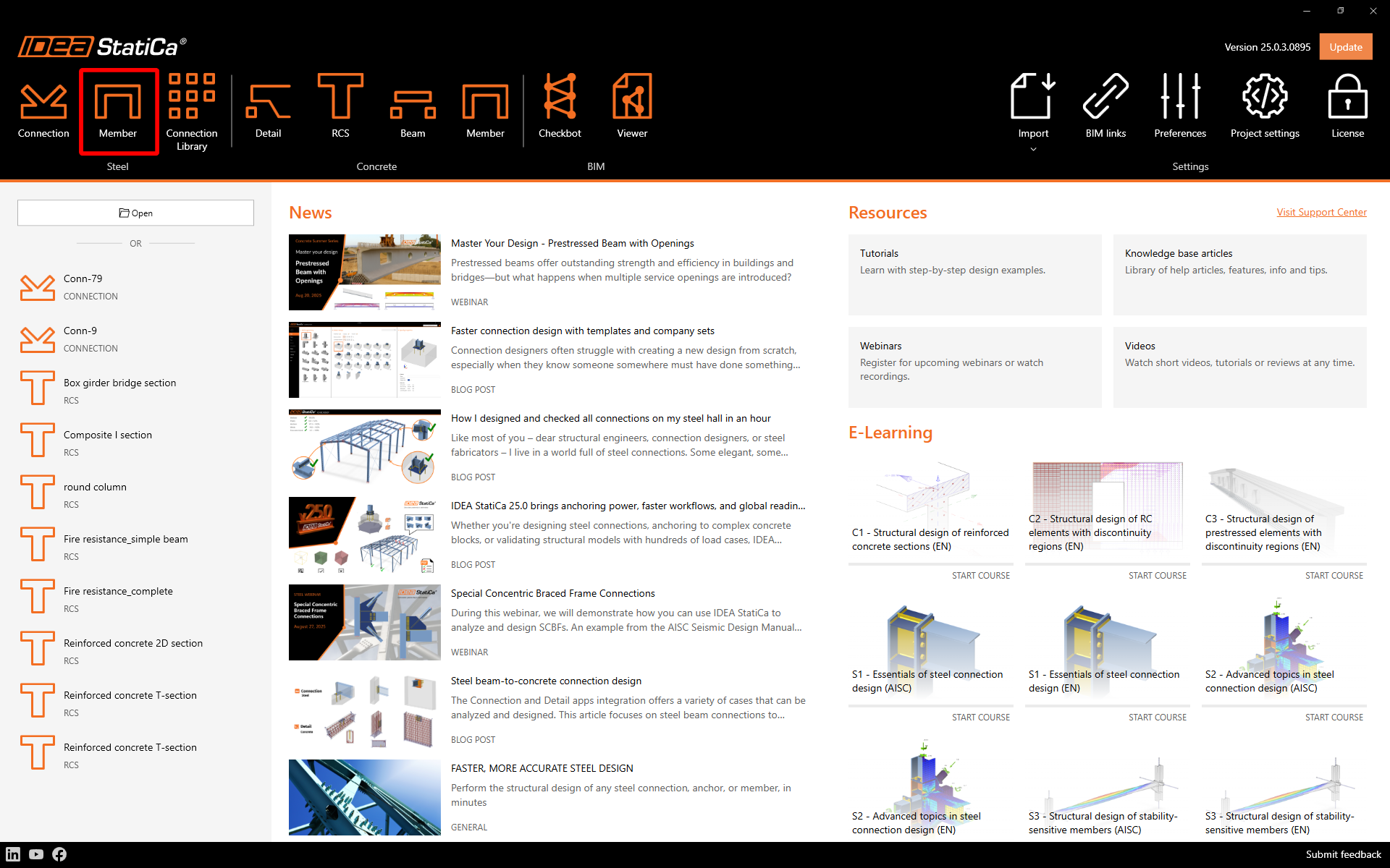
Hozzon létre egy új projektet, adja meg a nevét, és válasszon ki egy mappát, ahová menteni szeretné. Ezután válassza ki a tervezési szabványt, a kiindulási anyagtulajdonságokat és a topológia típusát. Adja meg az elemzett szerkezeti elem fesztávolságát 4 m-ben. Végül kattintson a Projekt létrehozása gombra, és kezdje el a szerkezeti részlet modellezését.
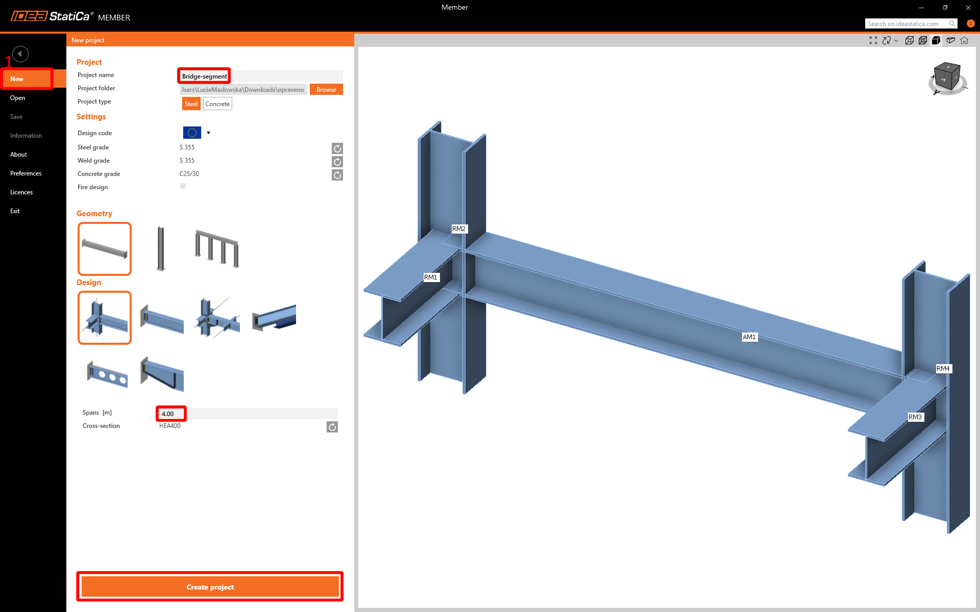
Az új projekt létrejön, és megkezdheti a tervezést.
2 Elemzett szerkezeti elemek
A szerkezeti részlet tervezésének kényelmes módja az IDEA StatiCa Member alkalmazásban, ha a 3D ablakban az entitások fájának sorrendjét követi felülről lefelé. Kezdje az Elemzett szerkezeti elemekkel.
Állítsa az Offset ez értékét -275 mm-re a globális végeselem-modell tulajdonságainak megfelelően.

3 Kapcsolódó szerkezeti elemek
A varázsló által generált kapcsolódó szerkezeti elemek nem rendelkeznek a megfelelő tulajdonságokkal, ezért mindegyiket törölni kell.

Az összes fennmaradó kapcsolódó szerkezeti elemet törölni kell. A projekt most az alábbi ábrán láthatóhoz hasonlít.

Most ideje hozzáadni a folytonos kapcsolódó szerkezeti elemeket a megfelelő irányban. A CON1-ben adjon hozzá egy folytonos kapcsolódó szerkezeti elemet Y irányban.

A hozzáadott RM2 kapcsolódó szerkezeti elemnél módosítsa a keresztmetszetet hegesztett I-szelvényre az alábbi képen látható paraméterekkel.

Végül módosítsa az RM2 hossztulajdonságait és peremfeltételeit.

Most ideje hozzáadni a második főgerendát a második folytonos kapcsolódó szerkezeti elemmel Y irányban a CON2 tulajdonságaiban.

Egyeztesse az RM3 tulajdonságait az RM2 tulajdonságaival.

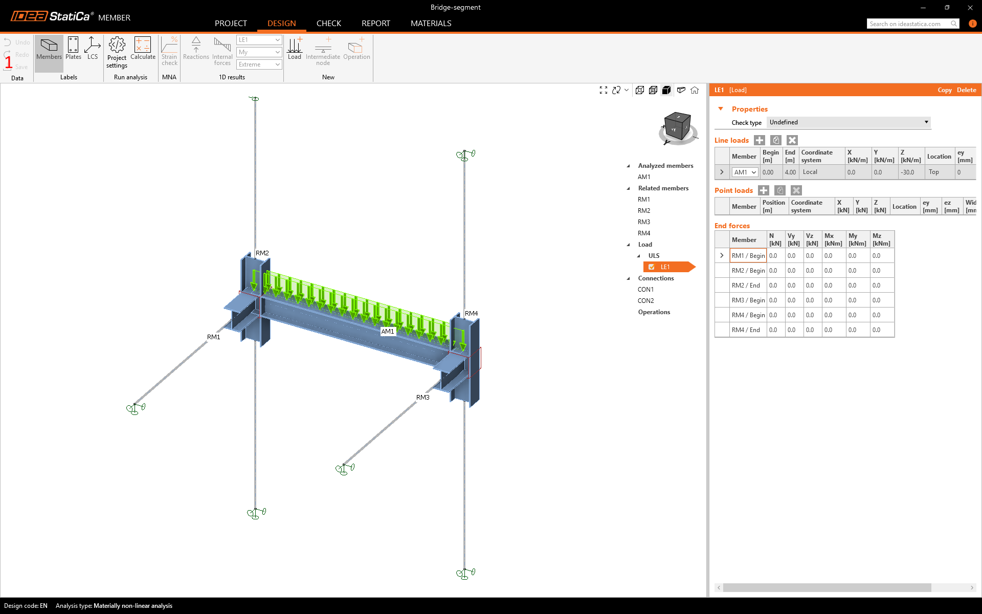
4 Terhek
Töltse be a Member modellt a globális végeselem-modellből összegyűjtött adatokkal. A terhek helyes beállításáról információt találhat az Elméleti háttérben.

5 Kapcsolatok
Továbbléphet az entitások fájának következő eleméhez a kapcsolatok tervezéséhez. Egyszerűen válassza a CON1-et és a Kapcsolat szerkesztése lehetőséget.

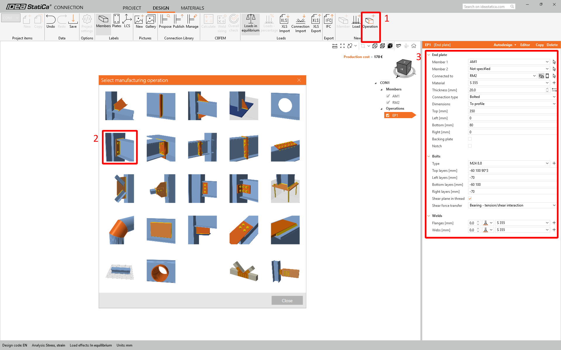
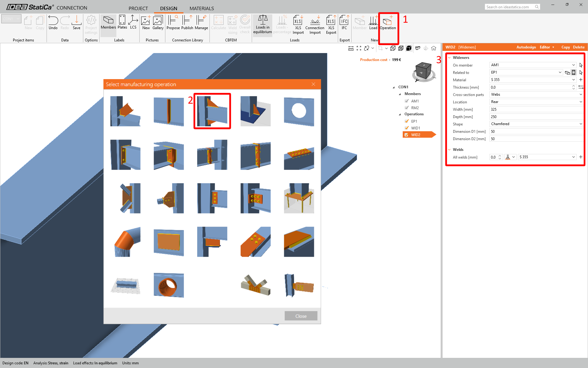
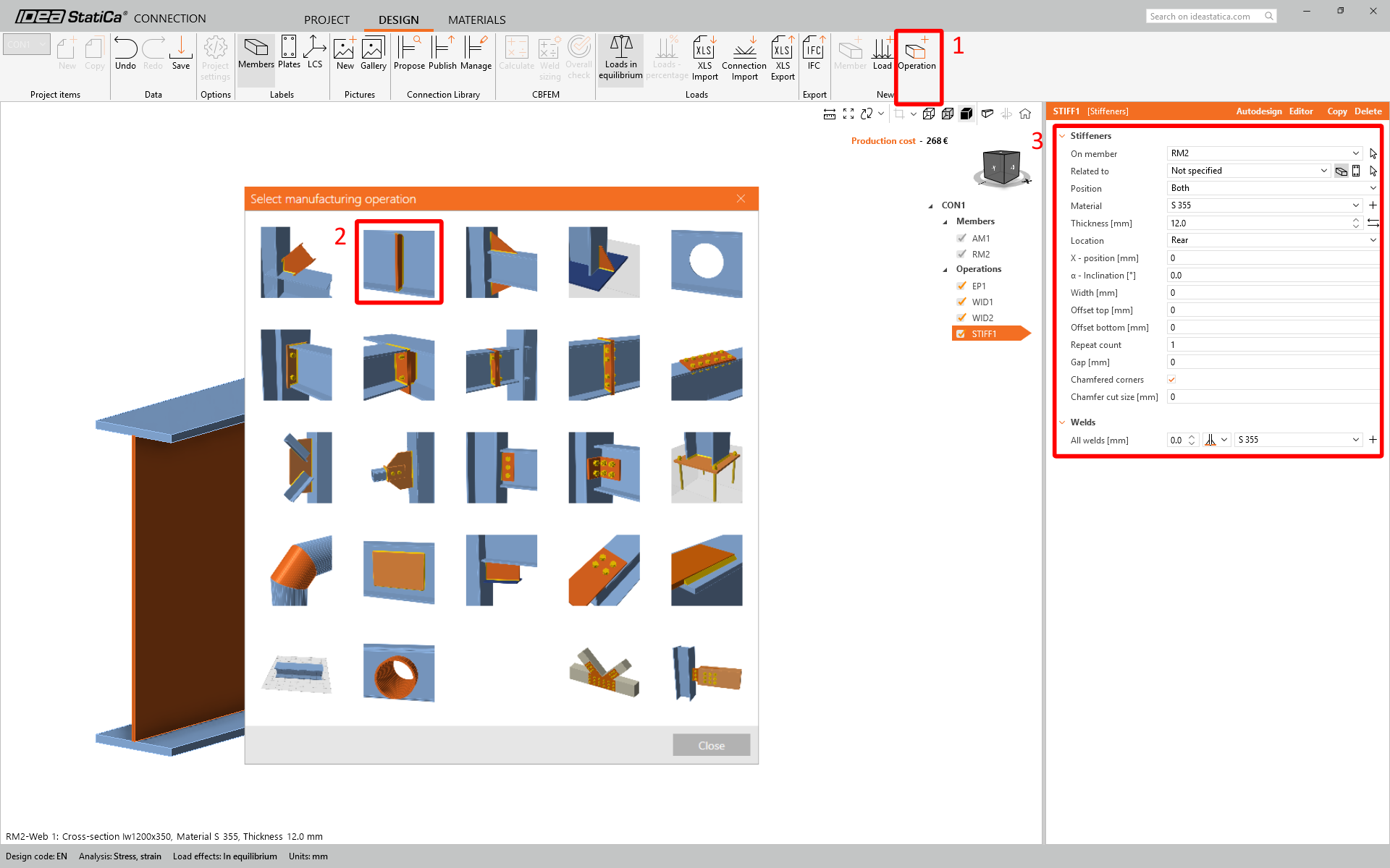
IDEA StatiCa Connection ablak néhány másodpercen belül megjelenik. Most létrehozhatja a kapcsolatot a szükséges műveletek hozzáadásával – homloklemez, elülső és hátsó szélesítő, valamint merevítő.

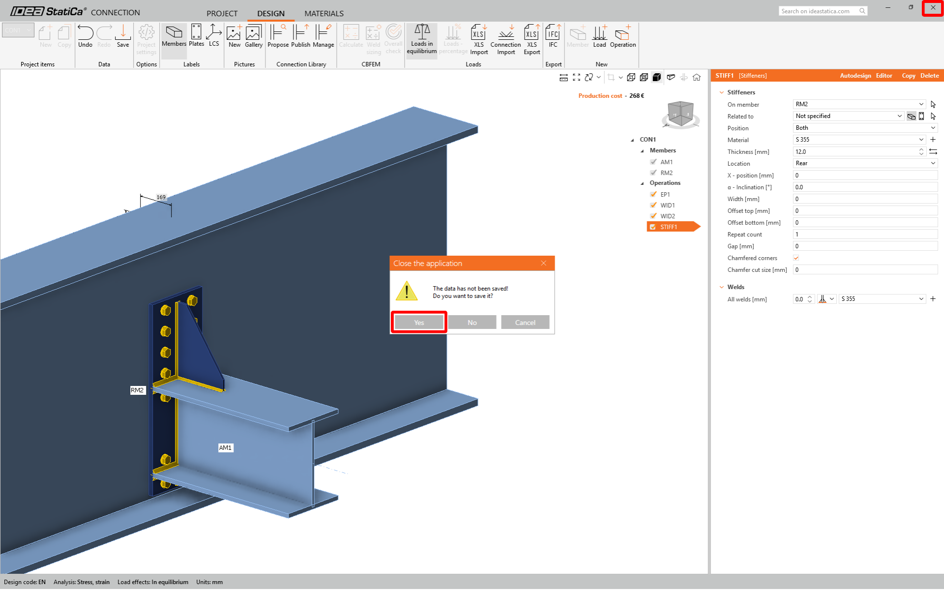
Most bezárhatja és mentheti a CON1-et.
A CON1 be van állítva. Most kattintson a CON2-re, és a Legutóbbi kapcsolat funkció segítségével alkalmazza ugyanazt a kapcsolatot a CON2-re.
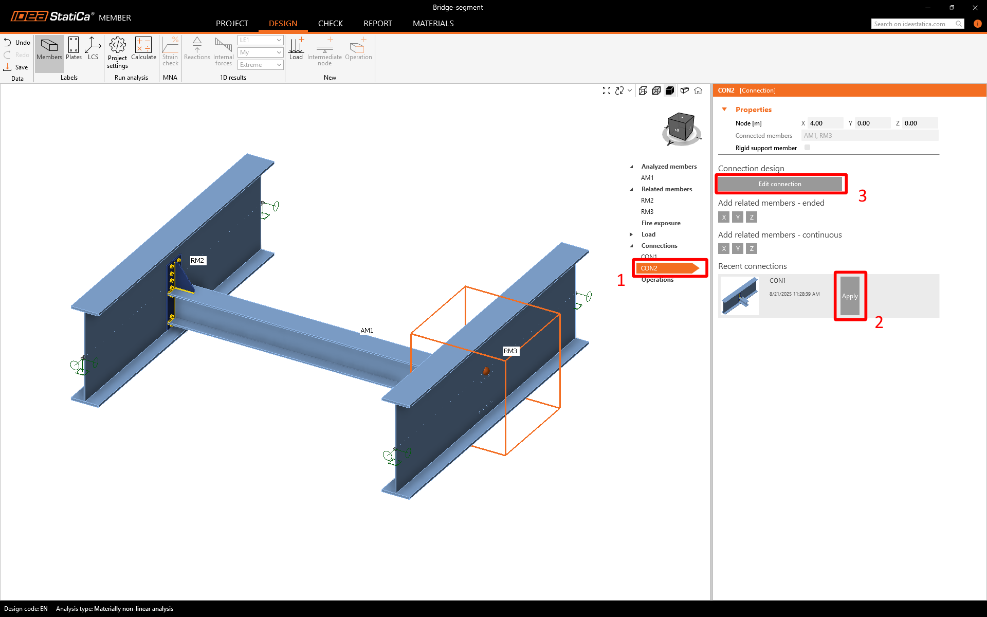
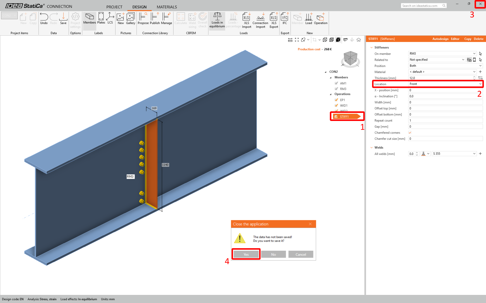
Amint látható, a merevítő helytelenül jött létre. Kattintson a Kapcsolat szerkesztése gombra, válassza ki a merevítőt, és módosítsa az Elhelyezést Elülsőre. Ezután bezárhatja az ablakot, és ne felejtse el menteni.
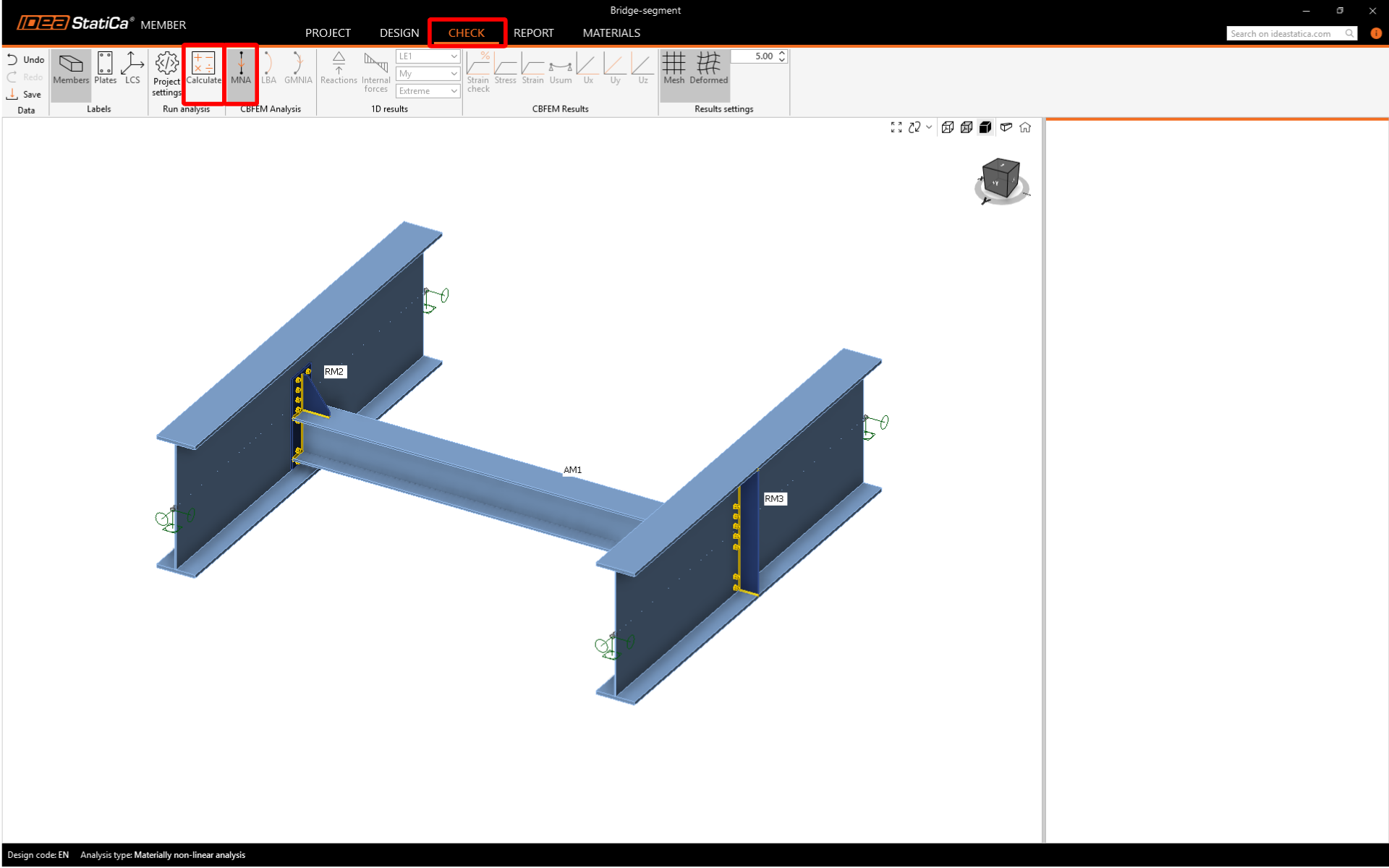
6 Ellenőrzés
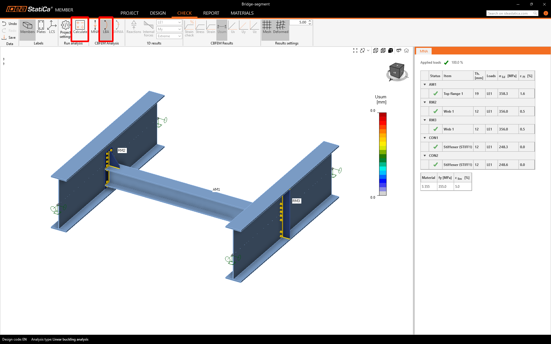
Az ellenőrzés most elvégezhető. Lépjen az Ellenőrzés fülre. Először az MNA elemzést kell elvégezni, majd az LBA elemzést, és az utolsó lépésben a GMNIA elemzés végezhető el. Ezt a sorrendet be kell tartani. Számítsa ki az MNA-t.
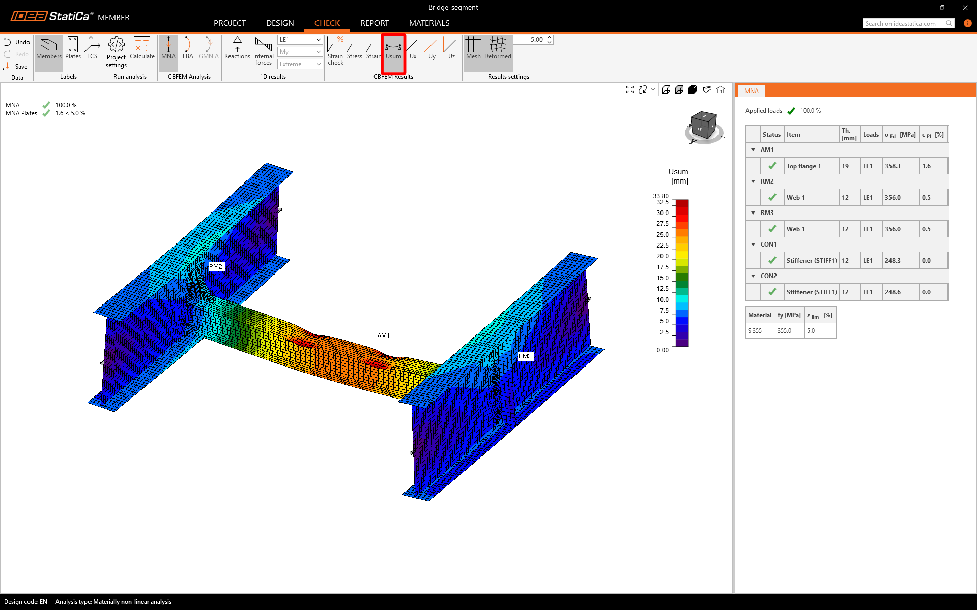
Az MNA eredmények megjelentek. Ellenőrizze az eredményeket, kapcsolja be az Usum deformációs nézetet, és tekintse meg az eredményeket.
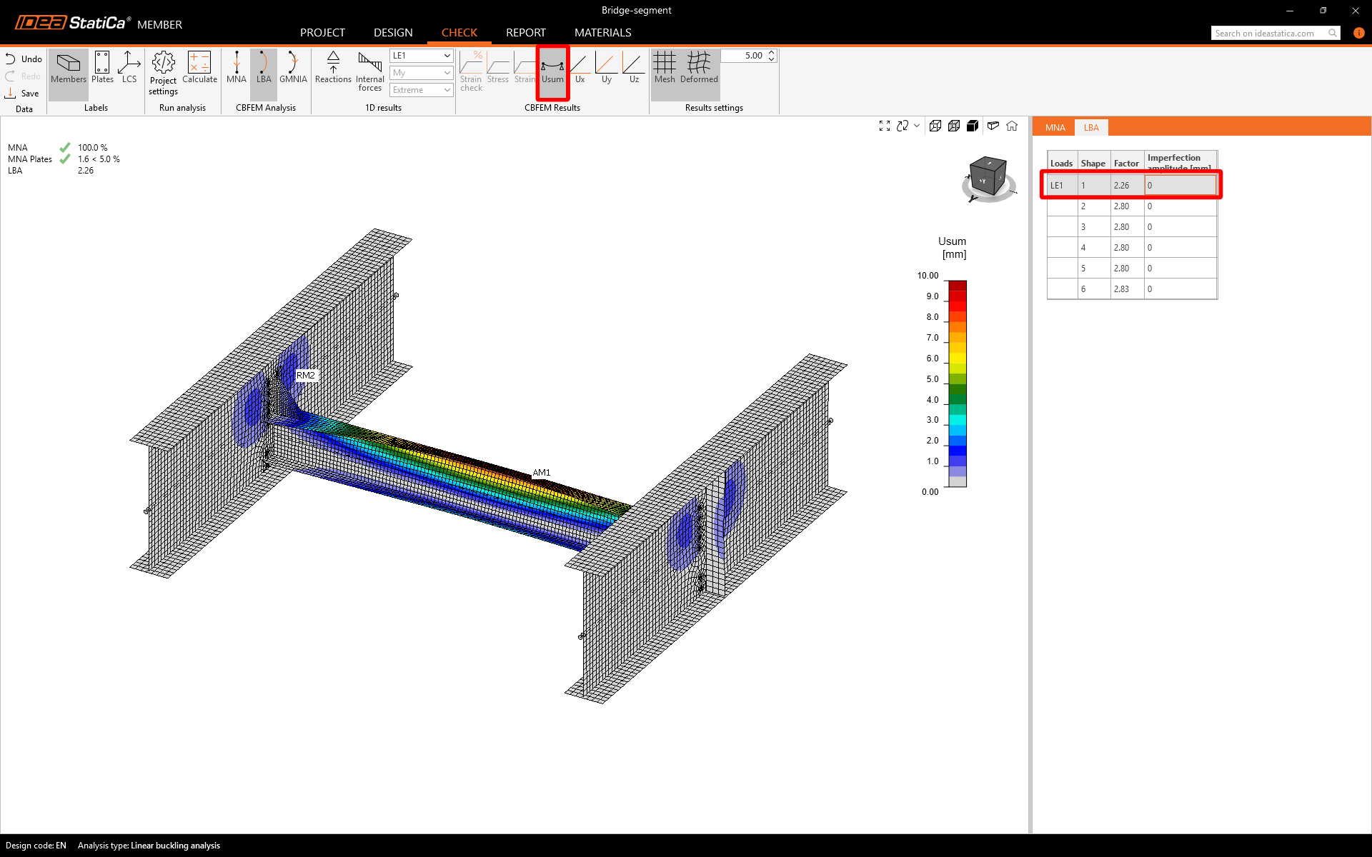
Most változtassa az elemzés típusát LBA-ra, és válassza a Számítás parancsot.
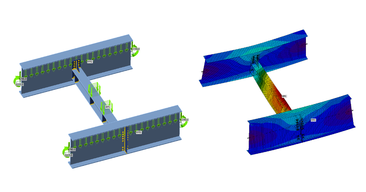
AzLBA eredmények megjelentek. Tekintse meg az első kihajlási alakot (az Usum deformált nézettel bekapcsolva vizuálisan egyértelműbb lesz). Ez a kihajlási alak a kifordulás (LTB) stabilitásvesztését jelenti.
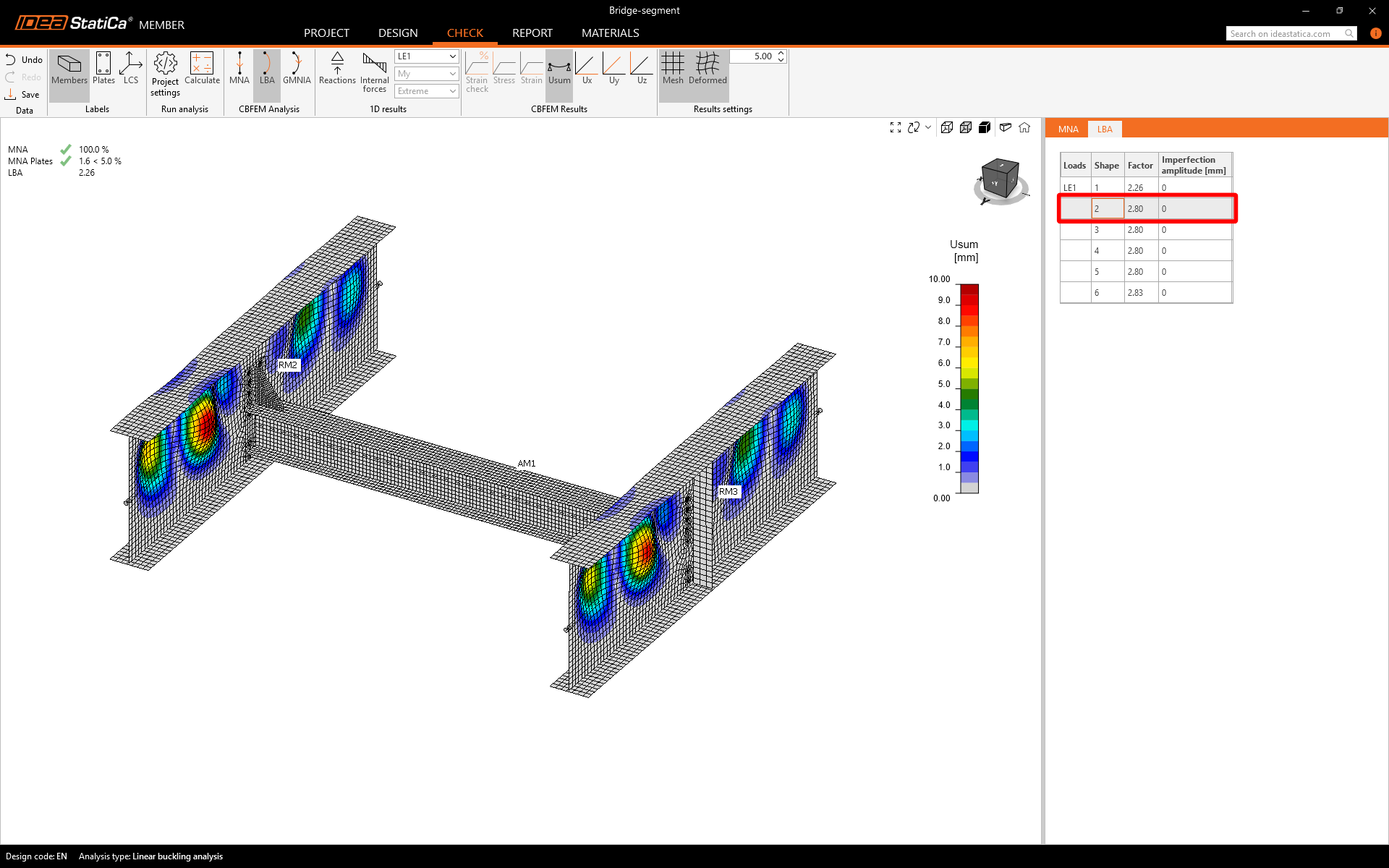
A második kihajlási alak a magas gerenda gerinc helyi kihajlását jelenti.
Az összes megadott kihajlási alakot végig kell vizsgálni, és el kell dönteni, melyik a legkritikusabb. Az IDEA StatiCa az első kihajlási alakot tekinti a legkritikusabbnak. Az EN 1993-1-1 szerint a helyi imperfekciókat az elemzett szerkezeti elemre számítják. Az IDEA StatiCa javasolja az imperfekciókat tárgyaló anyagok tanulmányozását.
Az elemzett szerkezeti elem hossza 4000 mm, L / 300 = 4000 / 300 = 13,33 mm. Elsősorban a kifordulás tönkremeneteli módot kívánja elemezni, ezért az excentricitás amplitúdóját k = 0,5-tel kell megszorozni.
Az imperfekció számított értéke az első kihajlási alakhoz 7 mm. Az imperfekcók beállítása után a Számítás paranccsal elindíthatja az elemzést.
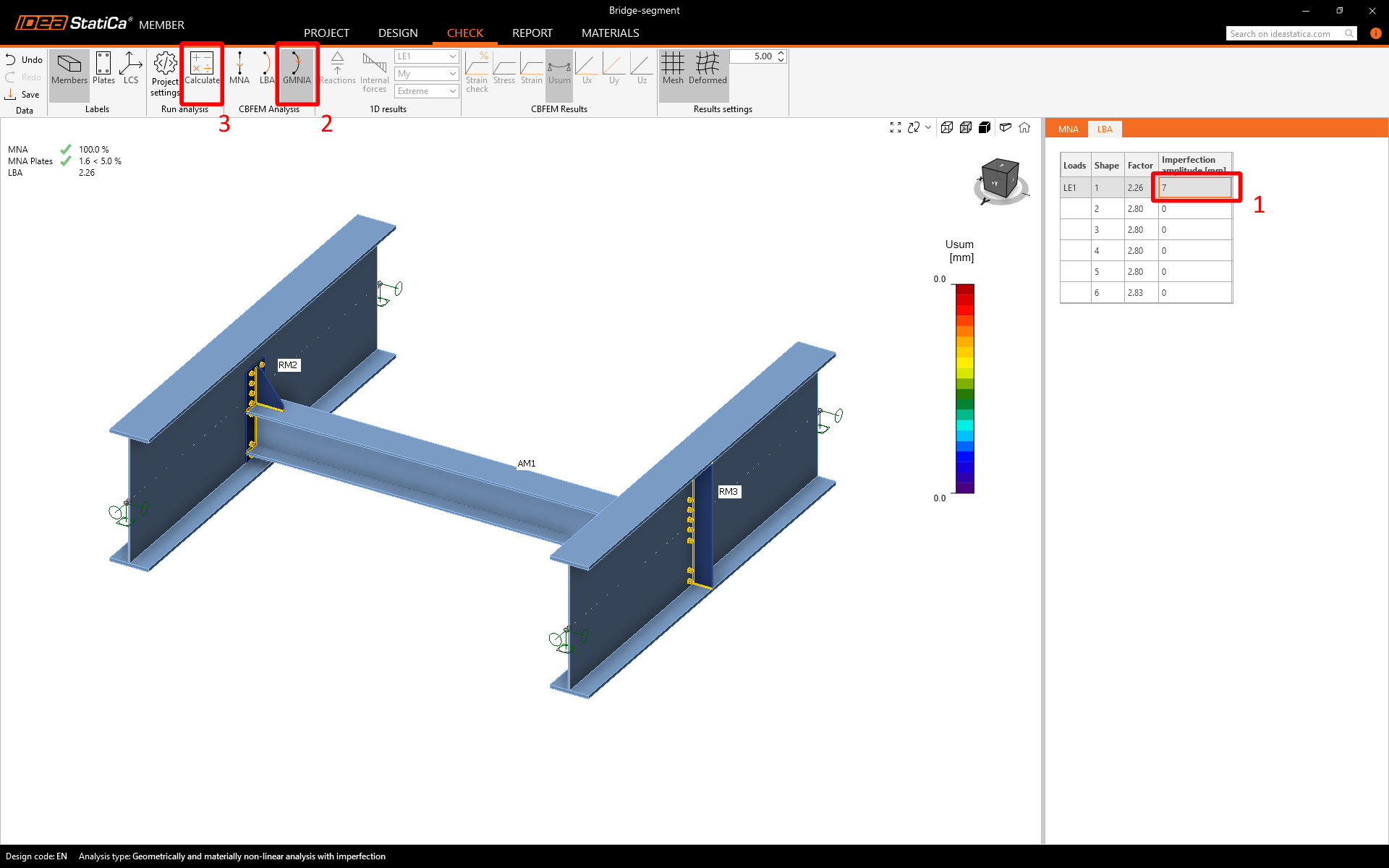
A GMNIA eredmények megjelentek, és látható, hogy a terhelés nem alkalmazható teljes mértékben. Látható a keresztgerenda felső övének képlékeny alakváltozása.
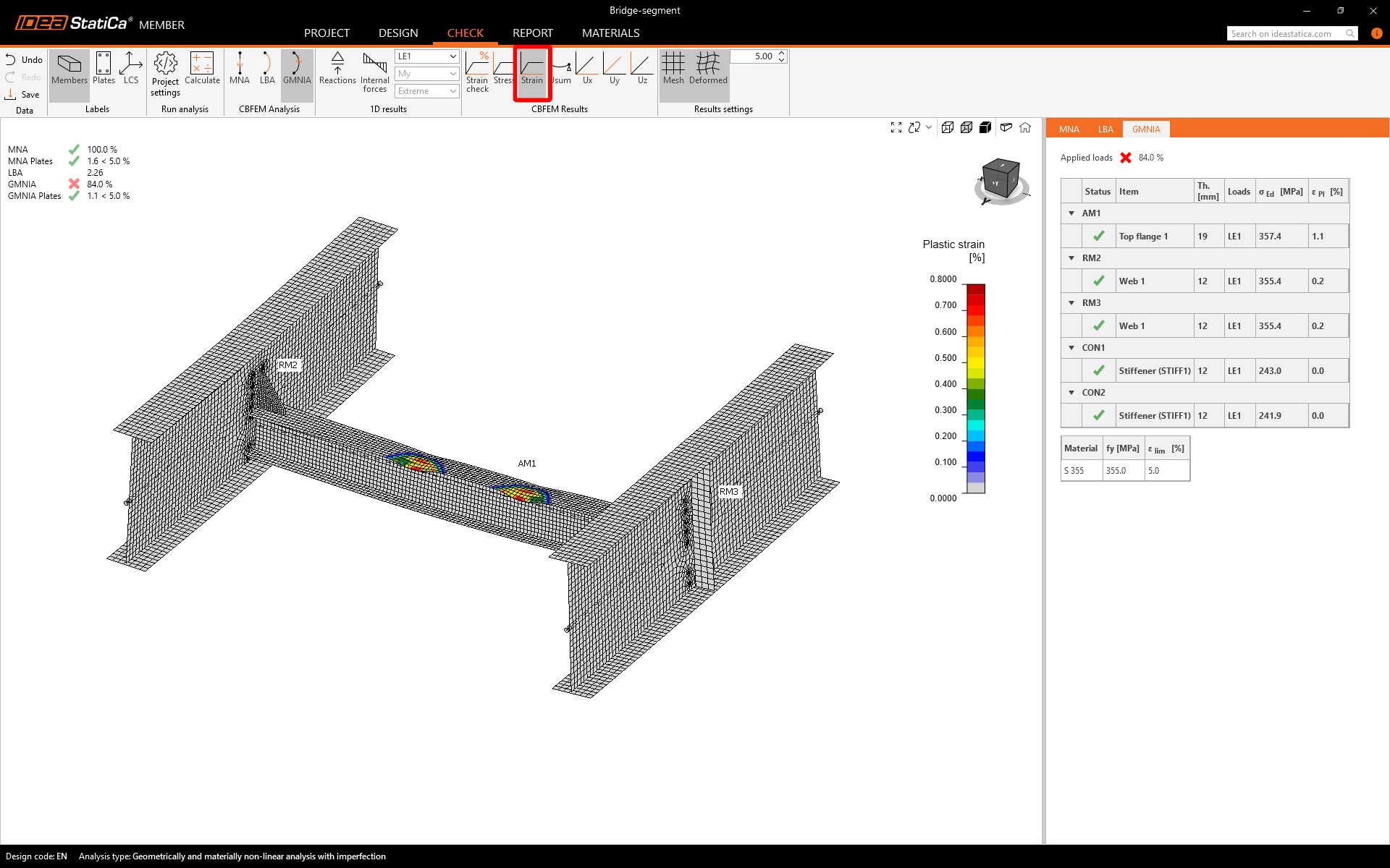
A teherbírás növeléséhez merevítőket adhat hozzá.
7 Műveletek
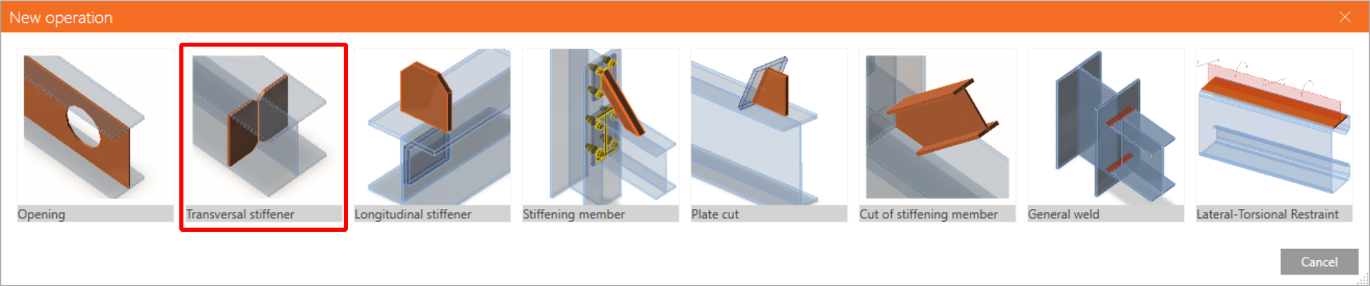
Lépjen a Tervezés fülre, és adjon hozzá egy Új műveletet az entitások fájábana Műveletek elemre jobb egérgombbal kattintva.

Válassza a Keresztirányú merevítő lehetőséget.
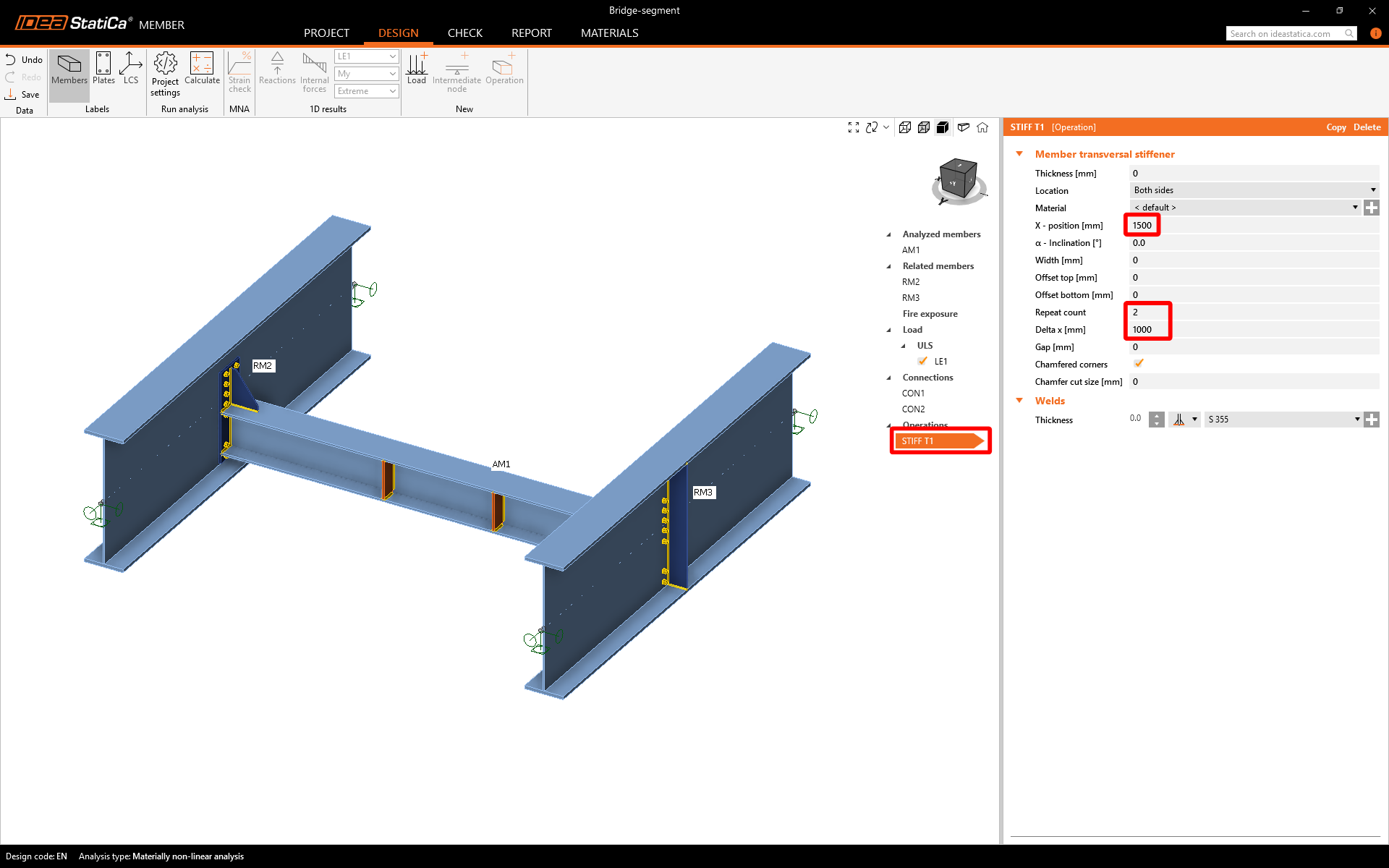
Állítsa be a STIFF T1 tulajdonságait az alábbi kép szerint.
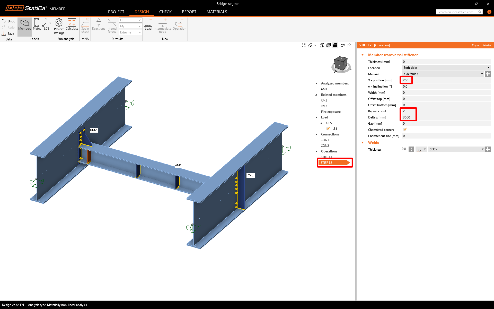
Adjon hozzá egy másik merevítőt, és állítsa be tulajdonságait az alábbi kép szerint.
Most ugyanúgy elindíthatja az összes elemzést, mint az előző alkalommal. Ellenőrizze a kapott eredményeket a merevítők elemzett szerkezeti elemre gyakorolt hatásával együtt.
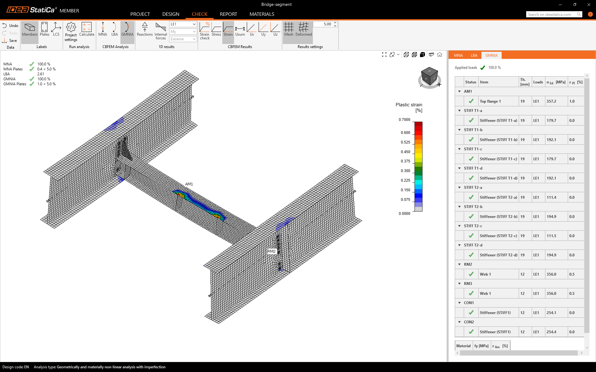
Most látható, hogy a terhelés 100%-a alkalmazásra került.
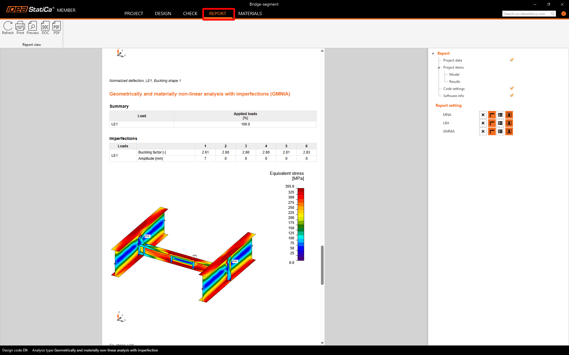
8 Jelentés
Végül lépjen a Jelentés fülre. Az IDEA StatiCa teljes mértékben testreszabható jelentést kínál, amely kinyomtatható vagy szerkeszthető formátumban menthető.
Megterveztük és ellenőriztük a rekeszgerendát az IDEA StatiCa Member alkalmazásban.