Member - boundary conditions
Introduction
IDEA StatiCa Member works with part of your structure that is “cut off” from your global 3D FEA model. Therefore, the program lets the definition of boundary conditions on an engineer's judgment.
In IDEA StatiCa Member, you can define boundary conditions at the ends of related members. The application offers to input:
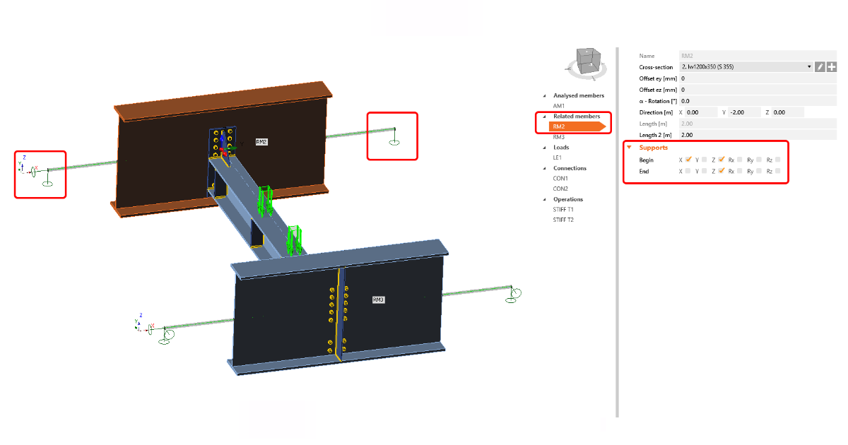
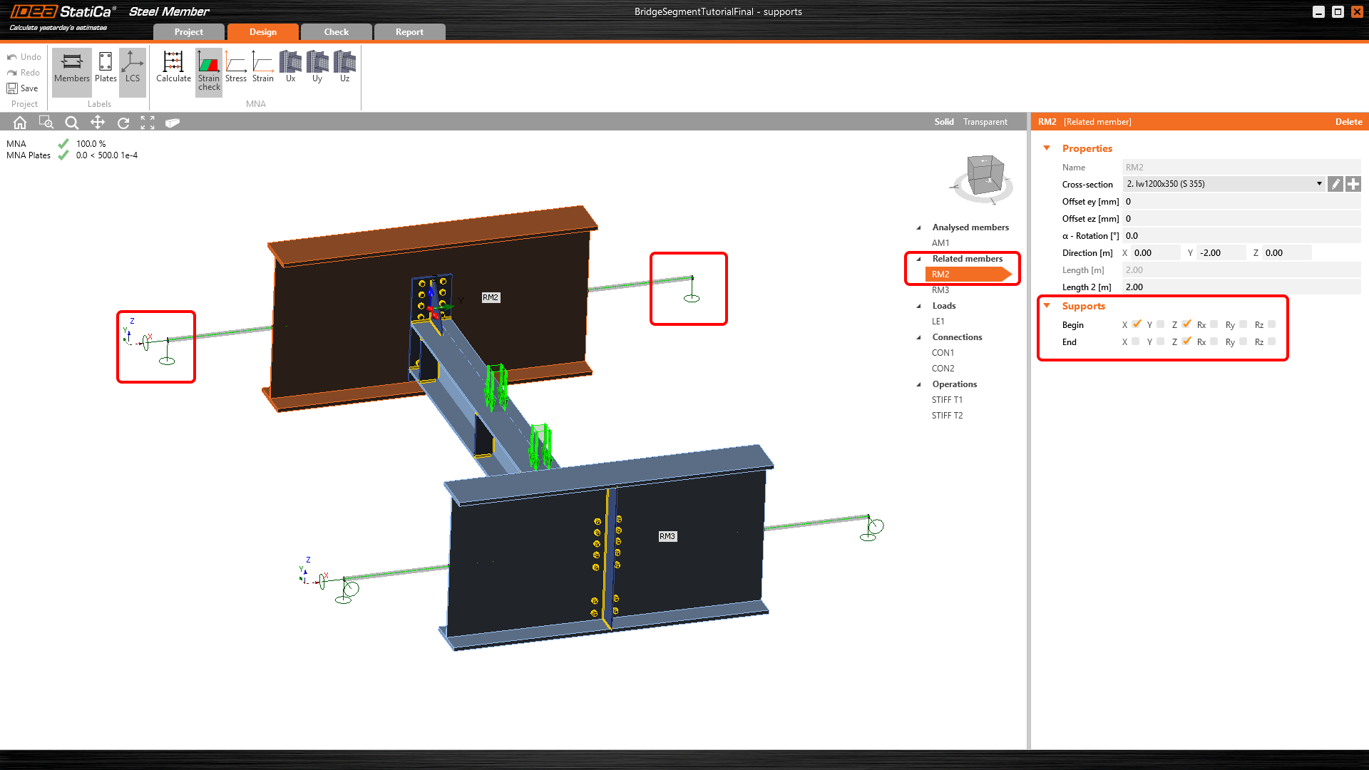
a) Supports – definition of supports should correspond to your 3D FEA model
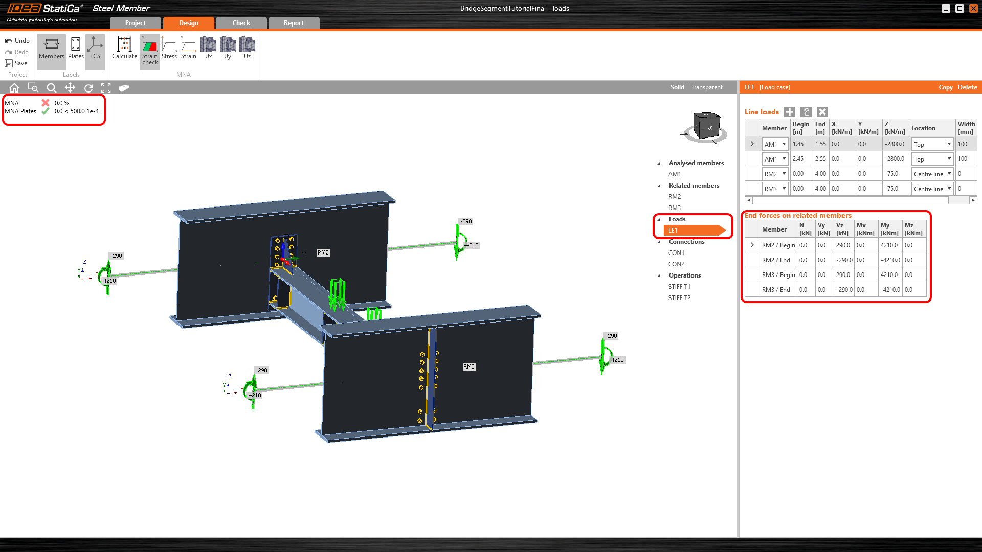
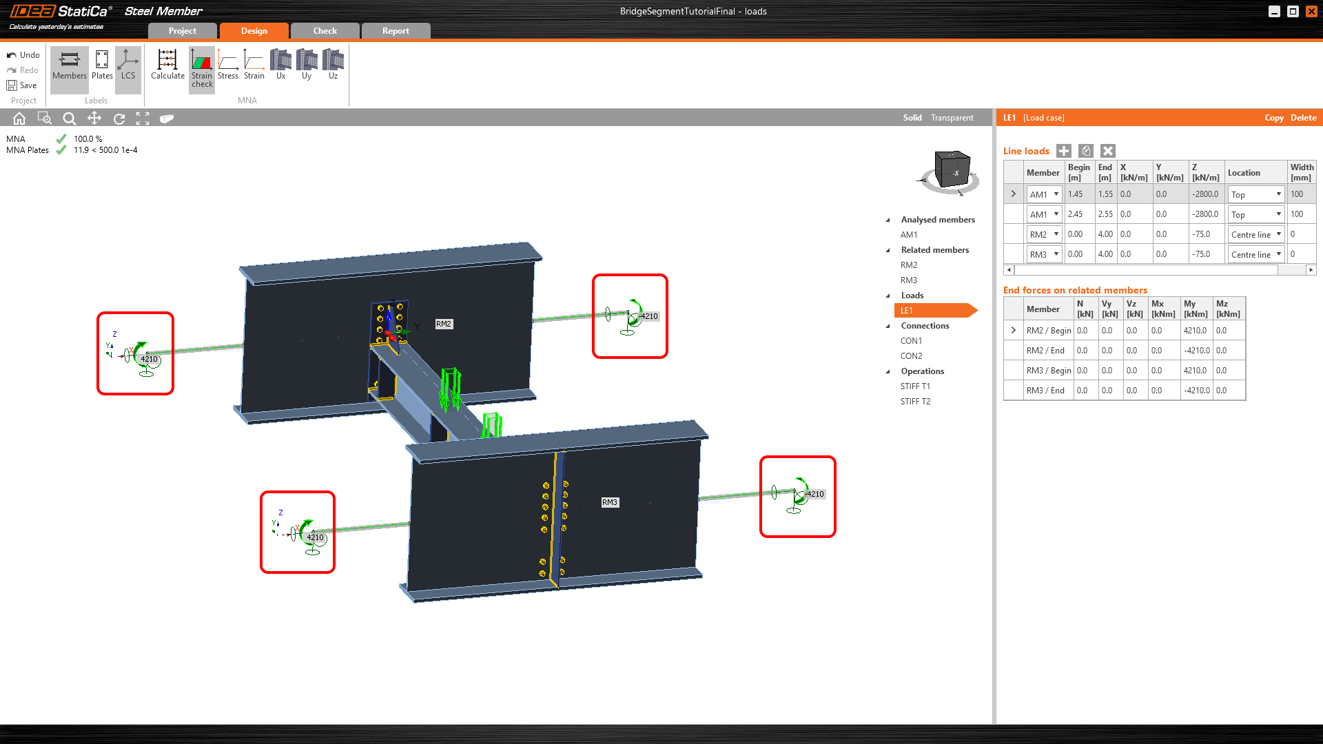
b) End forces on related members – correspond to internal forces calculated in the standard 3D FEA program
It is not possible to input only End forces on related members without using supports. A more precise model (e.g. local eccentricities of members, and real lengths of members are taken into account ) is used. Thus the imposed imperfections for the GMNIA analysis cause the equilibrium is not preserved, and the mechanism may, therefore, be defined.
Reasonable support based on structural engineer judgment is recommended.
c) Supports + End forces on related members – minimal reasonable supporting based on structural engineer judgment + add internal forces from your 3D FEA program.
Internal forces from the global model
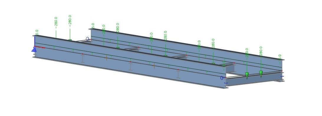
A segment of the structure is cut from a global model. The cut choice is entirely arbitrary and depends on the user's judgment. The model should be symmetrical, which is reflected in this case.
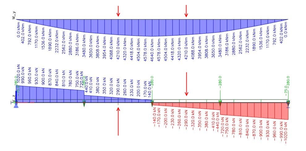
Fig. 01 Bending moments and shear forces on the main girder
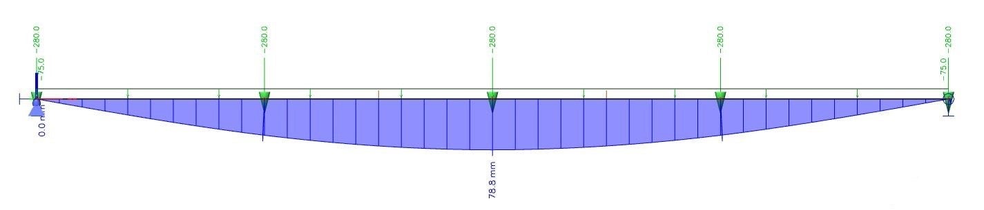
Fig. 02 Global deformation of the main girder

Fig. 03 Normal stress on the main girder
Impact of the boundary conditions in IDEA StatiCa Member
The boundary conditions have a huge impact on the behavior of a structure. The user should respect the global behavior of the structure during the modeling of the structural segment in IDEA StatiCa Member.
The boundary conditions ought to be chosen according to the behavior of the global model. Either translation or rotations shouldn't be restricted to any additional stresses that could be created. The ignorance of these rules will have a big impact on the results of all three available types of analyses: materially non-linear analysis (MNA), linear buckling analysis (LBA), and geometrically and materially non-linear analysis with imperfections (GMNIA).
The following points indicate the important rules:
- The model is in equilibrium after export if the internal forces (N, V, M) are added at the ends of related members.
- Boundary conditions serve to constrain the additional reactions, which were created after MNA, LBA and GMNIA analyses.
- Without boundary conditions, the model can't be calculated.
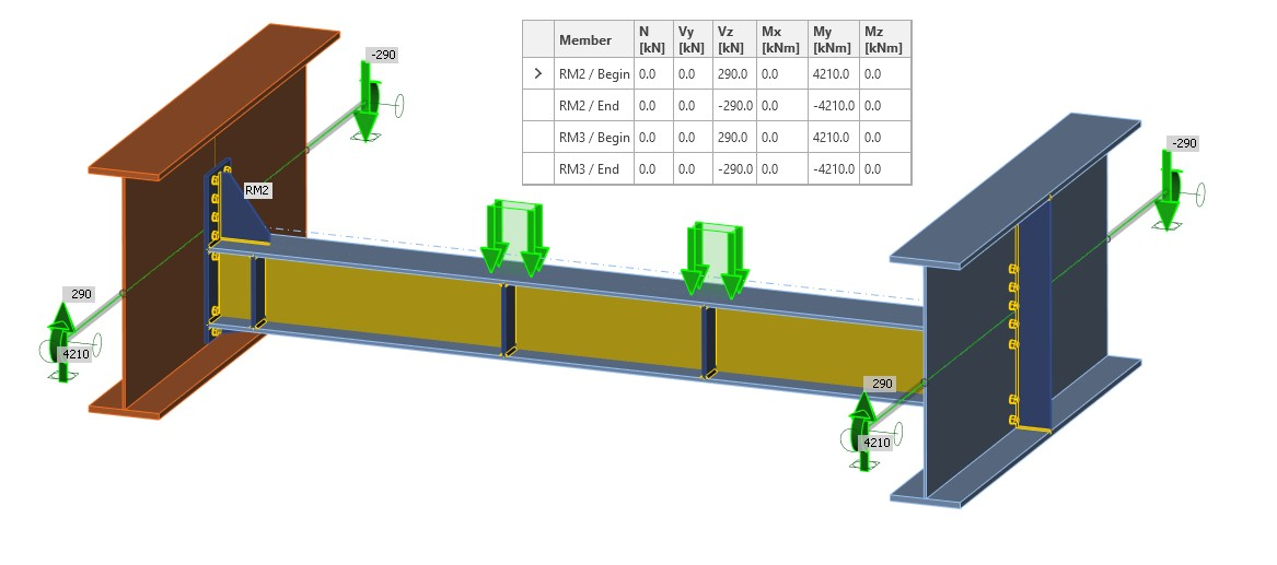
Fig. 04 Internal forces at the end of related members
Example 1: Correct boundary conditions and internal forces at the ends of related members
This model includes the boundary conditions corresponding to the global model, i.e. hinges (Fig. 05). Thanks to internal forces at the end of related members, you receive the corresponding diagram of internal forces as in the global model (Fig. 06).

Fig. 05 Hinges and internal forces at the end of related members
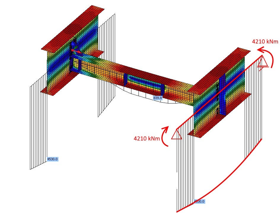
Fig. 06 Bending moments in the Member application
The equivalent stress and deformation prove that the boundary conditions and the diagram of internal forces (Fig.06) comply with the global model of the structure (Fig. 03). Results of equivalent stress are slightly higher than in the linear analysis in global FEM (Fig. 03) due to the plate model and consideration of the real stiffness of the connections between the diaphragm and the main girders.
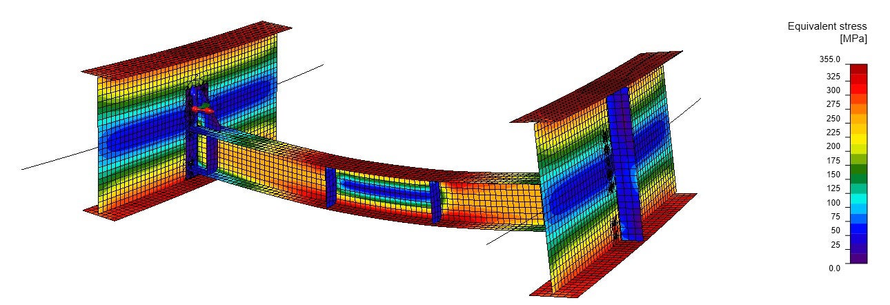
Fig. 07 Equivalent stress from the material non-linear analysis
The linear buckling analysis (LBA) shows that the first critical factor reaches a value of 2.66. The first mode shape causes the diaphragm to buckle (Fig. 08). The second factor is close to the first one and reaches a value of 3.14 (Fig. 09). This mode shape causes a local buckling of the web of the main girder. The mode shape and critical factor are influenced by the stiffness of the connections, the stiffness of the main girders, and also the boundary conditions.
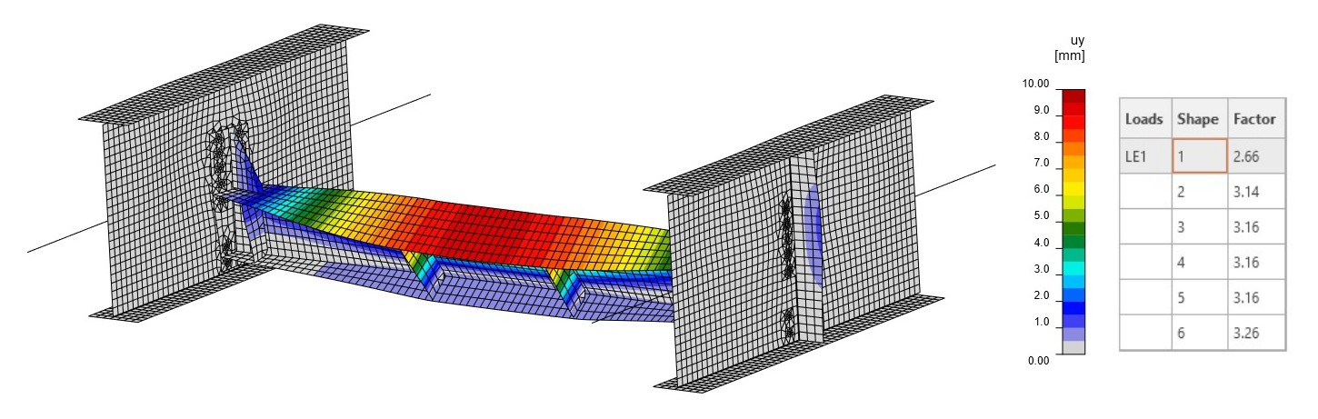
Fig. 08 First mode shape
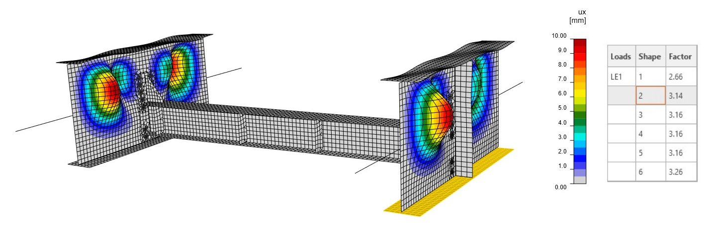
Fig. 09 Second mode shape
Example 2: Incorrect boundary conditions and internal forces at the end of related members
If we don't keep the correctness of the boundary conditions (Fig.10) at the end of related members, we receive entirely different internal forces (Fig. 11). This gives us already a clue that the boundary conditions are chosen incorrectly, and the cut part of the structure has different behavior than the global model (Fig. 01).
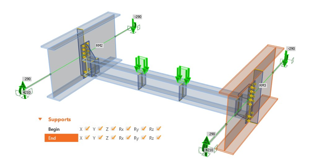
Fig. 10 Rigid boundary conditions and internal forces at the end of related members
These internal forces and stresses are entirely different from the global model. The boundary conditions influenced slightly also the internal forces of the diaphragm. (Fig. 11 vs. Fig. 06). Due to restrained translation and rotation (Rx), the redistributions of internal forces are different from Fig. 06.

Fig. 11 Bending moments in the Member application
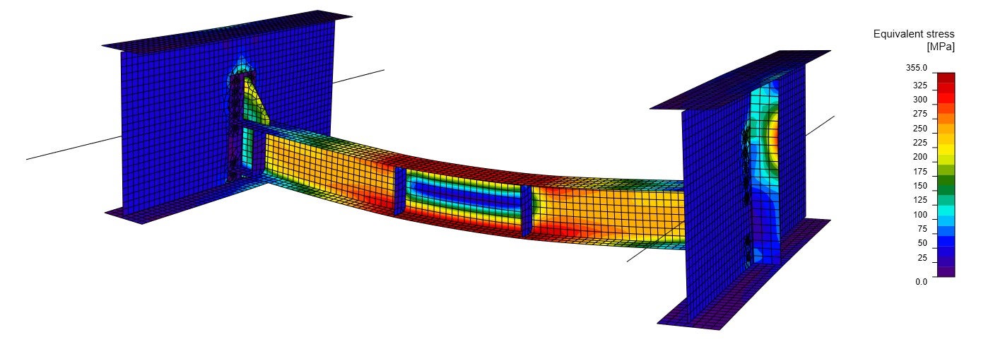
Fig. 12 Equivalent stress from the material non-linear analysis
The first mode shape gives a slightly higher critical factor of 2.70 (Fig. 13) compared to the first example (Fig. 08). This effect is caused by the different boundary conditions used in the model. This mode shape represents the diaphragm buckling, and, as we can see, the stresses and the internal forces are approximately the same as those in Fig. 06. This is the reason why the first mode shape looks similar and has almost the same factor. The boundary conditions have a small impact on parts in the segment model, which are indirectly connected with the related members. On the contrary, the second mode shape (Fig. 14) is totally different compared to the one in Fig. 09, with a critical factor of 6.23. Here, the buckling takes place on the upper flange of the diaphragm.
Looking only at the results of LBA, the model seems to be correct. Nevertheless, the behavior of the global structure is totally different, and thus the approach with such boundary conditions can't be used.
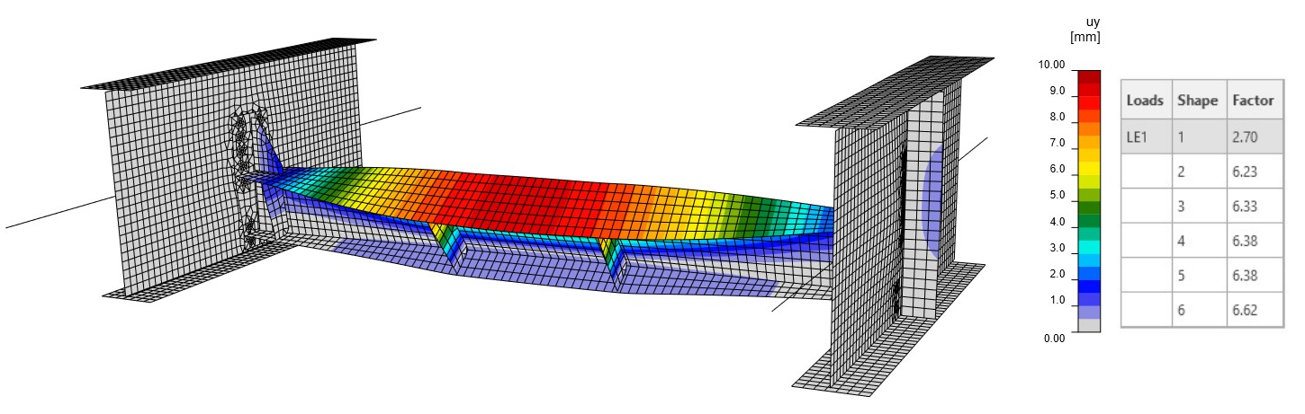
Fig. 13 First mode shape
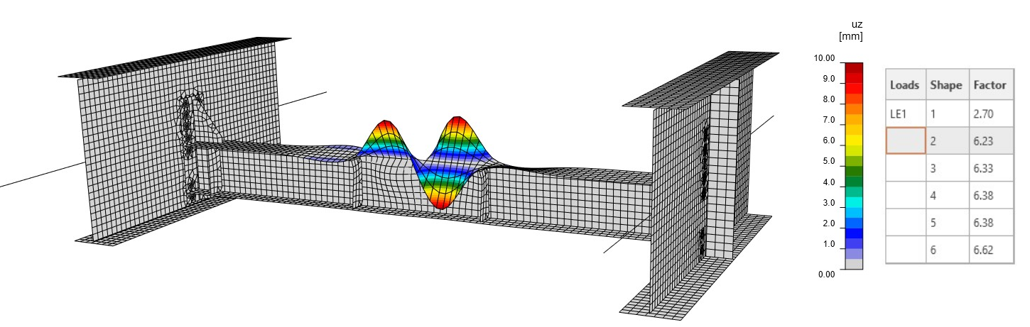
Fig. 14 Second mode shape
Example 3: Correct boundary conditions and any internal forces at the end of related members
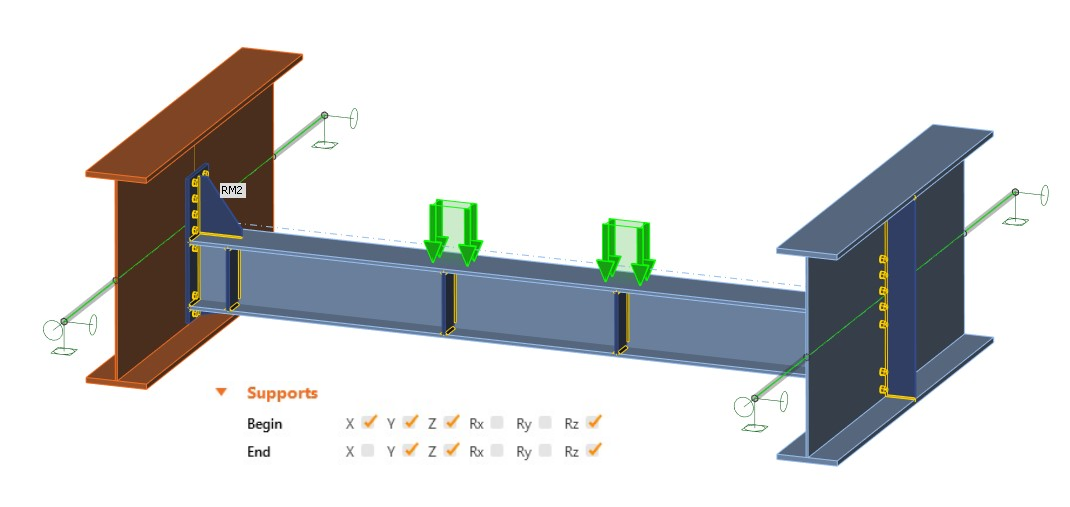
Fig. 15 Hinges and any internal forces at the end of related members
The correct boundary conditions (complying with the global model) but without any internal forces input at the end of related members (Fig. 15) cause the triangular shape of bending moments (Fig. 16). From the internal forces are evidently seen that this behavior does not comply with the global model behavior. One interesting phenom regarding the internal forces on the diaphragm in Fig. 16 can be observed - the internal forces are the same as in the model in the first model (Fig. 06). So we can conclude that if the boundary conditions are correctly defined, and any internal forces at the end of related members are applied, MNA on the indirectly connected members is performed correctly.
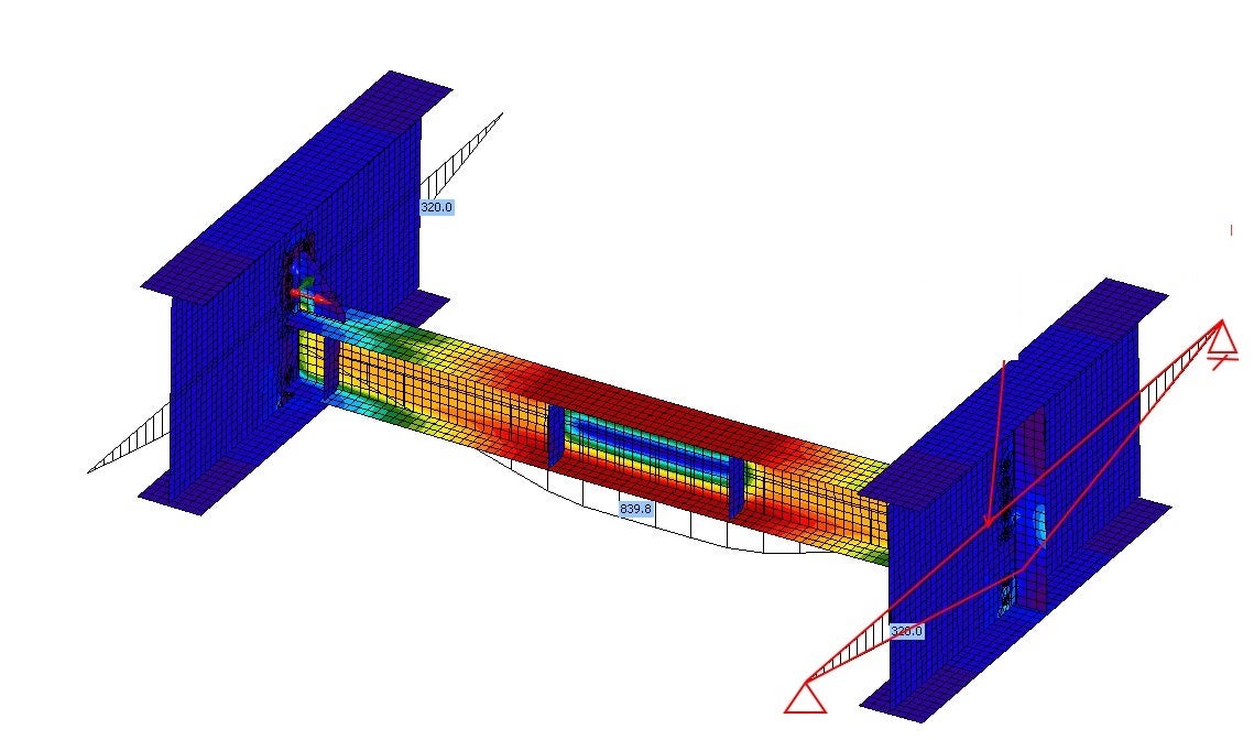
Fig. 16 Bending moments in the Member application
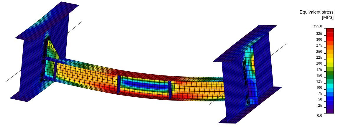
Fig. 17 Equivalent stress from the material non-linear analysis
The first mode shape complies with the first model (Fig. 08); thus, we can say that the GMNIA would be performed correctly. The second mode shape is similar to the second model (Fig. 14) due to missing internal forces at the end of related members.
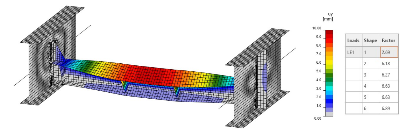
Fig. 18 First mode shape
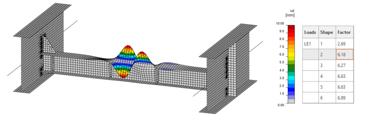
Fig. 19 Second mode shape
Conclusion
- The global model, deformations of the structural segment, and its internal forces and stresses are the clue for determining the correct boundary conditions.
- The boundary conditions affect the behavior of the related members.
- Even though the internal forces are not applied at the ends of related members, the MNA, LBA, and GMNIA analyses are performed correctly, provided that the appropriate boundary conditions have been defined.