CBFEM - fonctionnement, conformité normative, validation et vérification
La CBFEM est une méthode unique pour le dimensionnement et la vérification normative des assemblages acier, des éléments et des ancrages. Elle peut être utilisée pour la majorité des assemblages, des ancrages et des détails présentant des topologies variées.
La Méthode des Éléments Finis basée sur les Composants (CBFEM) est :
- Suffisamment générale pour être applicable à la plupart des assemblages, des fondations et des détails rencontrés dans la pratique de l'ingénierie.
- Suffisamment simple et rapide dans la pratique quotidienne pour fournir des résultats dans un délai comparable aux méthodes et outils actuels.
- Suffisamment complète pour fournir aux ingénieurs structure des informations claires sur le comportement de l'assemblage, les contraintes, les déformations, les réserves des composants individuels, ainsi que sur la sécurité et la fiabilité globales.
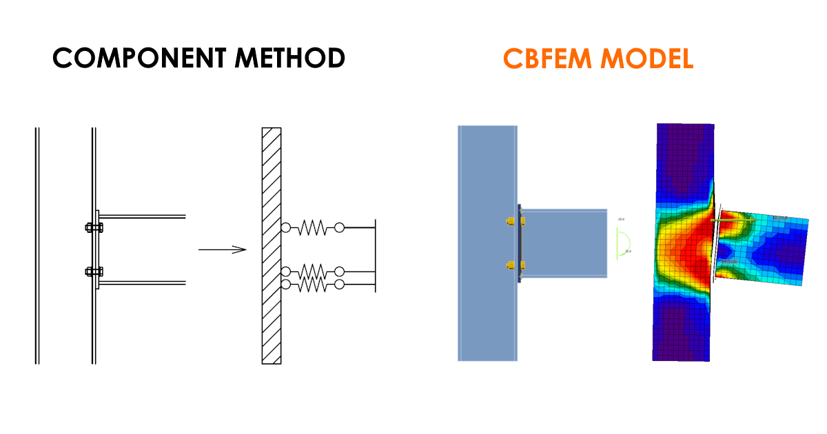
La vérification d'un assemblage selon la méthode des composants standard et selon la CBFEM utilisée dans IDEA StatiCa Connection repose sur la vérification de toutes les parties de l'assemblage – les composants. Les composants peuvent être des boulons, des ancrages, des soudures, des plaques et du béton au niveau de la fondation.
La CBFEM décompose l'ensemble de l'assemblage en composants distincts mentionnés ci-dessus. Le modèle d'analyse est ensuite créé automatiquement par le logiciel à partir de chaque composant.
La vérification elle-même comprend deux étapes :
- Les efforts dans chaque composant de l'assemblage sont calculés
- Chaque composant est vérifié à l'aide des équations normatives
Calcul des efforts
La CBFEM implémentée dans IDEA StatiCa Connection simplifie le comportement de chaque composant. Comment ?
Le modèle est composé d'éléments auxquels les charges sont appliquées et d'opérations de fabrication (y compris les éléments de raidissement), qui servent à relier les éléments entre eux.
Le modèle MEF analysé est généré automatiquement. Le concepteur ne crée pas le modèle MEF, il crée l'assemblage à l'aide d'opérations de fabrication.
Grâce à cela, les efforts sont calculés sans hypothèses simplificatrices. Les autres effets, tels que l'interaction des composants, etc., sont également calculés.
De plus, en raison de la prise en compte de la rigidité réelle des composants, les résultats incluent l'effort de levier. Rien n'est négligé.
Vérification et évaluation des résultats
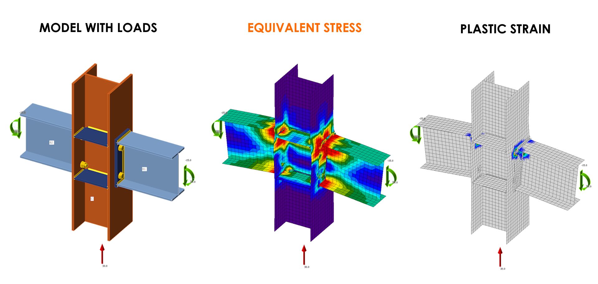
L'analyse de résistance est l'analyse la plus importante des assemblages. Les vérifications des déformations des plaques ainsi que les vérifications normatives des composants sont effectuées par une analyse élasto-plastique.
L'analyse des assemblages est matériellement non linéaire. Les incréments de charge sont appliqués progressivement et l'état de contrainte est recherché.
Vérification des plaques
Les plaques sont modélisées avec un matériau élasto-plastique présentant une pente nominale du palier de plastification conformément à EN 1993-1-5, Par. C.6, (2), tan-1 (E/1000).
Le comportement du matériau est basé sur le critère de plasticité de von Mises. Il est supposé élastique avant d'atteindre la limite d'élasticité de calcul fyd.
Le critère d'état limite ultime pour les zones non susceptibles de flambement est l'atteinte de la valeur limite de la déformation principale membranaire. Une valeur de 5 % est recommandée (par ex. EN 1993-1-5, Ann. C, Par. C.8, Note 1).
Parties spécifiques du fond théorique pour chacune des normes nationales prises en charge :
- Vérification normative des plaques selon EN (Eurocode)
- Vérification normative des plaques selon AISC (norme américaine)
- Vérification normative des plaques selon CISC (norme canadienne)
- Vérification normative des plaques selon AS (norme australienne)
- Vérification normative des plaques selon IS (norme indienne)
- Vérification normative des plaques selon GB (norme chinoise)
- Vérification normative des plaques selon HKG (Code of Practice de Hong Kong)
- Vérification normative des plaques selon SP (norme russe)
Vérification des autres composants
Les vérifications sont effectuées pour les efforts calculés à l'aide des mêmes équations que celles de la norme, dans toutes les méthodes. Les équations utilisées pour les boulons, les ancrages, les soudures et le massif en béton sont présentées dans l'application et peuvent être examinées en détail.
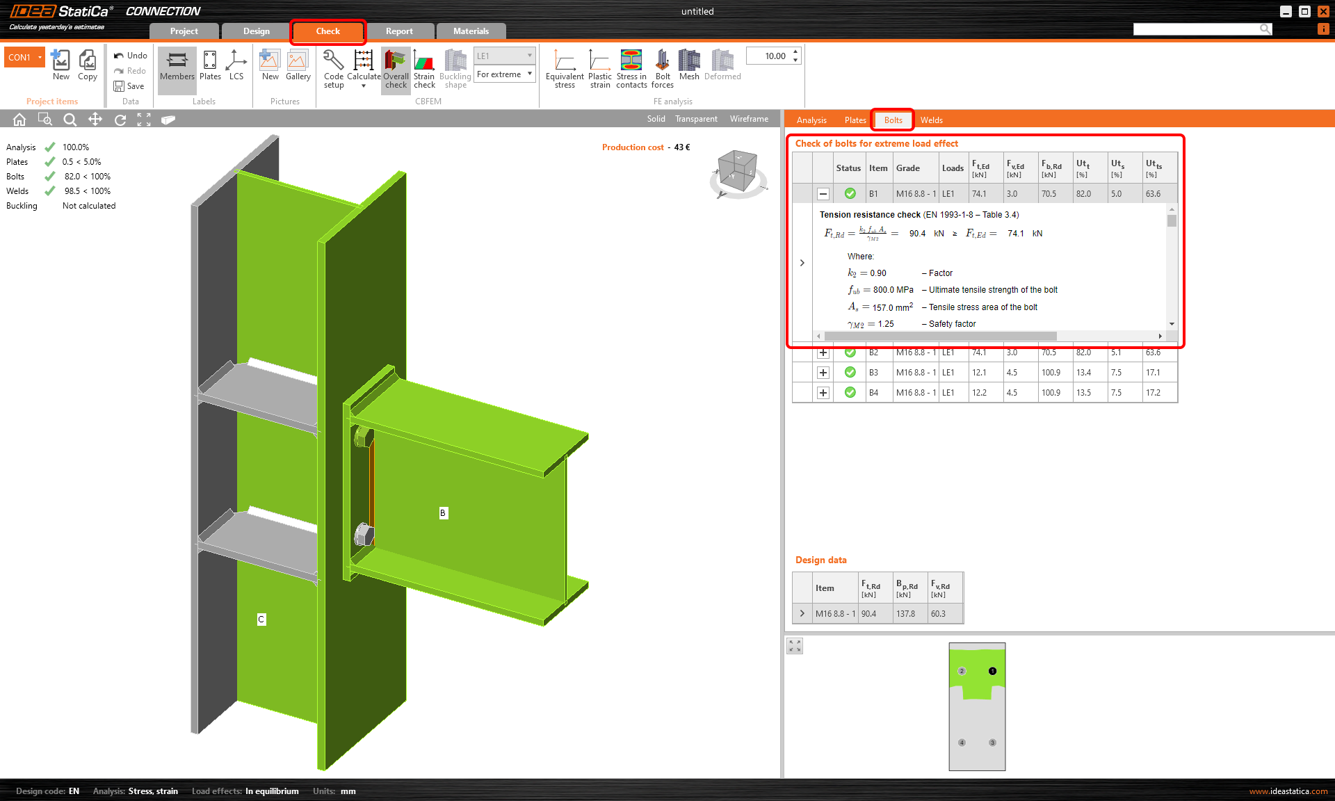
Vérification des boulons
Les boulons dans IDEA StatiCa Connection sont vérifiés conformément aux normes correspondantes. Pour plus d'informations, consultez l'article Boulons et assemblages boulonnés.
Vérification des soudures
Dans le cas des soudures également, la vérification est effectuée conformément aux normes correspondantes.
Des informations détaillées sur la vérification des soudures dans l'application Connection sont disponibles dans l'article Soudure/Soudures dans IDEA StatiCa.
Vérification du massif en béton
Les principes du calcul du massif en béton sont expliqués dans l'article Modèle structurel d'un massif en béton.
Parties spécifiques du fond théorique pour chacune des normes nationales prises en charge :
- Vérification normative d'un massif en béton selon EN (Eurocode)
- Vérification normative d'un massif en béton selon AISC (norme américaine)
- Vérification normative d'un massif en béton selon CISC (norme canadienne)
- Vérification normative d'un massif en béton selon AS (norme australienne)
- Vérification normative d'un massif en béton selon IS (norme indienne)
- Vérification normative d'un massif en béton selon GB (norme chinoise)
- Vérification normative d'un massif en béton selon HKG (Code of Practice de Hong Kong)
- Vérification normative d'un massif en béton selon SP (norme russe)
Comment la CBFEM peut-elle être conforme à la norme et au comportement réel en même temps ?
La MEF orientée dimensionnement (CBFEM) est optimisée pour fournir des résultats pertinents pour la vérification normative tout en couvrant le comportement réel de la structure. Elle prend simultanément en compte la marge de sécurité définie par la norme.
Regardez la vidéo et trouvez la réponse à vos questions.
Caractéristiques clés de l'analyse CBFEM
Avez-vous déjà entendu les acronymes MNA ou GMNA implémentés dans le logiciel, sans savoir ce qu'ils signifient ? Les propriétés de l'analyse, la non-linéarité du matériau ou de la géométrie. Qu'est-ce qui est recommandé et réalisé par la CBFEM ?
Regardez la vidéo suivante et découvrez les différentes approches.
Validation et vérification
À l'origine, deux équipes universitaires ont consacré plus de trois ans à la vérification et à la validation de la méthode CBFEM.
Au fil du temps, de nombreuses nouvelles études de vérification ont été menées en coopération avec des universités du monde entier (États-Unis, Pays-Bas, Allemagne, Suisse, Amérique du Sud, et bien d'autres).
Que signifient exactement la validation et la vérification ? Le processus de validation et de vérification confirme que les résultats du logiciel sont corrects.
La vérification est une comparaison avec une méthode analytique, le plus souvent intégrée dans le code de construction (par ex. AISC, EN, etc.).
Les méthodes analytiques des normes sont grevées de simplifications, et les résultats entre la norme et la CBFEM pour des assemblages complexes peuvent varier, notamment aux limites du domaine de validité. Dans ce cas, une comparaison de la CBFEM avec un modèle avancé validé par des expériences prouve que la CBFEM est sûre, même si les résistances sont supérieures à celles déterminées par la norme.
La validation est une comparaison d'un modèle numérique avec une expérience.
Le modèle numérique est souvent très avancé, incluant des non-linéarités matérielles et géométriques. La géométrie et les propriétés des matériaux sont identiques à celles mesurées lors de l'expérience. Lorsque les résultats – typiquement des courbes charge-déplacement et contrainte-déformation – du modèle numérique sont proches de ceux de l'expérience, le modèle numérique est validé. Les propriétés des matériaux du modèle numérique sont ensuite modifiées pour prendre des valeurs nominales, les imperfections sont augmentées conformément aux tolérances de fabrication, et plusieurs études de sensibilité peuvent être réalisées en faisant varier des paramètres, par ex. l'épaisseur des plaques, la limite d'élasticité du matériau.
Enfin, les résultats du modèle numérique sont comparés à ceux de la CBFEM. Les résultats n'ont pas besoin de coïncider parfaitement, mais ils doivent être sûrs et les différences doivent se situer dans une plage acceptable.
Les exemples de vérification et de validation les plus importants ont été publiés dans l'ouvrage « Dimensionnement par éléments finis basé sur les composants des assemblages acier. »
Dans notre Centre d'assistance, vous pouvez trouver de nombreuses études de vérification ainsi que des comparaisons avec des essais en laboratoire. Retrouvez-les en utilisant le lien ci-dessous.